P CTP PB M EA 4 P X 3 b07.2 | 2008-10-05 - SKF.com
P CTP PB M EA 4 P X 3 b07.2 | 2008-10-05 - SKF.com
P CTP PB M EA 4 P X 3 b07.2 | 2008-10-05 - SKF.com

Create successful ePaper yourself
Turn your PDF publications into a flip-book with our unique Google optimized e-Paper software.
ContentsThe <strong>SKF</strong> brand now stands for morethan ever before, and means moreto you as a valued customer.While <strong>SKF</strong> maintains its leadership as ahigh-quality bearing manufacturerthroughout the world, new dimensionsin technical advances, product supportand services have evol ved <strong>SKF</strong> into atruly solutions-oriented supplier,creating greater value for customers.These solutions enable customers toimprove productivity, not only withbreakthrough application-specific products,but also through leading-edgedesign simulation tools and consultancyservices, plant asset efficiency maintenanceprogram mes, and the industry’smost advanced supply managementtechniques.The <strong>SKF</strong> brand still stands for the verybest in rolling bearings, but it nowstands for much more.<strong>SKF</strong> – the knowledge engineering<strong>com</strong>pany<strong>SKF</strong> Couplings ................... 3<strong>SKF</strong> Grid Couplings .. . . . . . . . . . . . . . 4Selection .. . . . . . . . . . . . . . . . . . . . . . . 4Standard selection method. ....... 4Standard selection example.. . . . . . . 5Formula method .. . . . . . . . . . . . . . . 5Formula selection example .. . . . . . . 5Engineering data.. . . . . . . . . . . . . . . . . 6Order data.. . . . . . . . . . . . . . . . . . . . . . 8Full spacer and half spacercoupling types .. . . . . . . . . . . . . . . . . 8Horizontal and vertical cover types . . 8Installation . . . . . . . . . . . . . . . . . . . . . . <strong>10</strong><strong>SKF</strong> grid removal.. . . . . . . . . . . . . . . <strong>10</strong><strong>SKF</strong> Gear Couplings .. . . . . . . . . . . . . . 16Selection .. . . . . . . . . . . . . . . . . . . . . . . 16Standard selection method. ....... 16Standard selection example.. . . . . . . 17Formula method .. . . . . . . . . . . . . . . 17Formula selection example .. . . . . . . 18Engineering data.. . . . . . . . . . . . . . . . . 18Order data.. . . . . . . . . . . . . . . . . . . . . . 18Installation . . . . . . . . . . . . . . . . . . . . . . 20Floating shaft gear couplings . ....... 30Flex hubs on floating shafts ........ 30Rigid hubs on floating shaft .. . . . . . . 30Solid floating shaft selection ....... 31<strong>SKF</strong> Flex Couplings . .............. 34Selection .. . . . . . . . . . . . . . . . . . . . . . . 34Example....................... 34Engineering data.. . . . . . . . . . . . . . . . . 34Power ratings .................. 34Order data.. . . . . . . . . . . . . . . . . . . . . . 36Installation . . . . . . . . . . . . . . . . . . . . . . 37<strong>SKF</strong> Flex Spacer Coupling. .......... 40Installation....................... 41To dismantle. .................. 41<strong>SKF</strong> Chain Couplings. ............. 44Selection .. . . . . . . . . . . . . . . . . . . . . . . 44Example....................... 44Engineering data.. . . . . . . . . . . . . . . . . 45Power ratings .................. 45Order data.. . . . . . . . . . . . . . . . . . . . . . 45Installation....................... 46<strong>SKF</strong> FRC Couplings.. . . . . . . . . . . . . . . 48Selection .. . . . . . . . . . . . . . . . . . . . . . . 48Example....................... 48Engineering data.. . . . . . . . . . . . . . . . . 48Power ratings .................. 48Order data.. . . . . . . . . . . . . . . . . . . . . . 48Installation....................... 50<strong>SKF</strong> Jaw Couplings.. . . . . . . . . . . . . . . 52Selection .. . . . . . . . . . . . . . . . . . . . . . . 52Example....................... 52Engineering data.. . . . . . . . . . . . . . . . . 52Power ratings .................. 52Order data.. . . . . . . . . . . . . . . . . . . . . . 52Installation....................... 54<strong>SKF</strong> Universal Joints. ............. 56Selection .. . . . . . . . . . . . . . . . . . . . . . . 56Example....................... 56Engineering data.. . . . . . . . . . . . . . . . . 56Order data.. . . . . . . . . . . . . . . . . . . . . . 56General engineering dataon <strong>SKF</strong> Couplings.. . . . . . . . . . . . . . . . 58Lubrication.. . . . . . . . . . . . . . . . . . . . . 62General purpose grease............. 62Shaft alignment tools. ............ 63TM<strong>EA</strong> series...................... 63TM<strong>EA</strong> 2 .. . . . . . . . . . . . . . . . . . . . . . . . 64TM<strong>EA</strong> 1P/2,5.. . . . . . . . . . . . . . . . . . . . 64TM<strong>EA</strong> 1PEx .. . . . . . . . . . . . . . . . . . . . . 65Thermal printer TM<strong>EA</strong> P1. . . . . . . . . . . 65Machinery shims TMAS series.. . . . . . . 66Inspection tool .. . . . . . . . . . . . . . . . . . 67Stroboscope TMRS 1.. . . . . . . . . . . . . . 67<strong>SKF</strong> – the knowledge engineering<strong>com</strong>pany.. . . . . . . . . . . . . . . . . . . . . . . 682
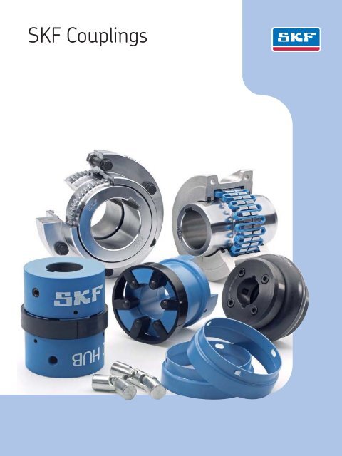
<strong>SKF</strong> CouplingsFlexible couplings are devices used to mechanicallyconnect two shafts to transmitpower from one shaft to the other. They arealso able to <strong>com</strong>pensate for shaft misalignmentin a torsionally rigid way. Misalignmentcan be angular, parallel or skew. This is particularlyimportant for applications wheremisalignment could affect the velocity andacceleration of the driven shaft. The performanceof the coupling depends largelyupon how it is installed, aligned andmaintained.In response to industry's ultimate need toproduce more with less, <strong>SKF</strong> has <strong>com</strong>binedits knowledge and experience with the latesttechnology to develop solutions for a varietyof applications and operating conditions.Whether the goal is to design equipmentthat provides more customer value, or toimprove overall profitability, <strong>SKF</strong>’s experienceand expertise can help you meet your goals.<strong>SKF</strong> offers a wide range of standard andcustomised coupling products. <strong>SKF</strong> Couplingscover a wide range of coupling types,sizes and capacity ratings for many applicationsand factory environments.For large, heavy duty applications, <strong>SKF</strong>has large size couplings. These couplings,which provide optimum contact with theshaft, can ac<strong>com</strong>modate high torque values,while reducing power loss and minimizingthe effects of misalignment.3
Engineering dataFor additional useful information on gridcouplings, such as an interchange guide,misalignment capability, puller bolt hole,inertia and standard stock spacer lengthsdata, please refer to tables 1 to 6.Table 1Table 3<strong>SKF</strong> grid coupling interchange guideHorizontal split coverPuller bolt hole data<strong>SKF</strong> Falk Morse/BrowningDodge Kop-Flex Lovejoy BibbyPHE <strong>10</strong>20TGHRSB <strong>10</strong>20T<strong>10</strong> GF2020H <strong>10</strong>20T<strong>10</strong> <strong>10</strong>20H <strong>10</strong>20 2020HPHE <strong>10</strong>30TGHRSB <strong>10</strong>30T<strong>10</strong> GF2030H <strong>10</strong>30T<strong>10</strong> <strong>10</strong>30H <strong>10</strong>30 2030HPHE <strong>10</strong>40TGHRSB <strong>10</strong>40T<strong>10</strong> GF2040H <strong>10</strong>40T<strong>10</strong> <strong>10</strong>40H <strong>10</strong>40 2040HPHE <strong>10</strong>50TGHRSB <strong>10</strong>50T<strong>10</strong> GF2<strong>05</strong>0H <strong>10</strong>50T<strong>10</strong> <strong>10</strong>50H <strong>10</strong>50 2<strong>05</strong>0HPHE <strong>10</strong>60TGHRSB <strong>10</strong>60T<strong>10</strong> GF2060H <strong>10</strong>60T<strong>10</strong> <strong>10</strong>60H <strong>10</strong>60 2060HPHE <strong>10</strong>70TGHRSB <strong>10</strong>70T<strong>10</strong> GF2070H <strong>10</strong>70T<strong>10</strong> <strong>10</strong>70H <strong>10</strong>70 2070HPHE <strong>10</strong>80TGHRSB <strong>10</strong>80T<strong>10</strong> GF2080H <strong>10</strong>80T<strong>10</strong> <strong>10</strong>80H <strong>10</strong>80 2080HPHE <strong>10</strong>90TGHRSB <strong>10</strong>90T<strong>10</strong> GF2090H <strong>10</strong>90T<strong>10</strong> <strong>10</strong>90H <strong>10</strong>90 2090HPHE 1<strong>10</strong>0TGHRSB 1<strong>10</strong>0T<strong>10</strong> GF2<strong>10</strong>0H 1<strong>10</strong>0T<strong>10</strong> 1<strong>10</strong>0H 1<strong>10</strong>0 2<strong>10</strong>0HPHE 11<strong>10</strong>TGHRSB 11<strong>10</strong>T<strong>10</strong> GF21<strong>10</strong>H 11<strong>10</strong>T<strong>10</strong> 11<strong>10</strong>H 11<strong>10</strong> 21<strong>10</strong>HPHE 1120TGHRSB 1120T<strong>10</strong> GF2120H 1120T<strong>10</strong> 1120H 1120 2120HPHE 1130TGHRSB 1130T<strong>10</strong> GF2130H 1130T<strong>10</strong> 1130H 1130 2130HPHE 1140TGHRSB 1140T<strong>10</strong> GF2140H 1140T<strong>10</strong> 1140H 1140 2140HPHE 1150TGHRSB 1150T<strong>10</strong> – – – 1150 –PHE 1160TGHRSB 1160T<strong>10</strong> – – – 1160 –PHE 1170TGHRSB 1170T<strong>10</strong> – – – 1170 –PHE 1180TGHRSB 1180T<strong>10</strong> – – – 1180 –PHE 1190TGHRSB 1190T<strong>10</strong> – – – 1190 –PHE 1200TGHRSB 1200T<strong>10</strong> – – – 1200 –B.C.D.Size B.C.D. Bolt Size B.C.D. Bolt– mm – – mm –PHE <strong>10</strong>70TGRSB 74 M8 PHE 1140TGRSB 2<strong>05</strong> M16PHE <strong>10</strong>80TGRSB 89,5 M8 PHE 1150TGRSB 227,5 M20PHE <strong>10</strong>90TGRSB <strong>10</strong>6 M<strong>10</strong> PHE 1160TGRSB 260 M20PHE 1<strong>10</strong>0TGRSB 121,5 M<strong>10</strong> PHE 1170TGRSB 306 M24PHE 11<strong>10</strong>TGRSB 136,5 M<strong>10</strong> PHE 1180TGRSB 341 M30PHE 1120TGRSB 150,5 M12 PHE 1190TGRSB 393 M30PHE 1130TGRSB 185 M16 PHE 1200TGRSB 414 M30Table 2Table 4<strong>SKF</strong> grid coupling interchange guideVertical split coverMisalignment capability<strong>SKF</strong> Falk Morse/BrowningDodge Kop-Flex Lovejoy BibbyPPHE <strong>10</strong>20TGVRSB <strong>10</strong>20T20 GF2020V <strong>10</strong>20T20 <strong>10</strong>20V <strong>10</strong>20 2020 VPHE <strong>10</strong>30TGVRSB <strong>10</strong>30T20 GF2030V <strong>10</strong>30T20 <strong>10</strong>30V <strong>10</strong>30 2030 VPHE <strong>10</strong>40TGVRSB <strong>10</strong>40T20 GF2040V <strong>10</strong>40T20 <strong>10</strong>40V <strong>10</strong>40 2040 VPHE <strong>10</strong>50TGVRSB <strong>10</strong>50T20 GF2<strong>05</strong>0V <strong>10</strong>50T20 <strong>10</strong>50V <strong>10</strong>50 2<strong>05</strong>0 VPHE <strong>10</strong>60TGVRSB <strong>10</strong>60T20 GF2060V <strong>10</strong>60T20 <strong>10</strong>60V <strong>10</strong>60 2060 VPHE <strong>10</strong>70TGVRSB <strong>10</strong>70T20 GF2070V <strong>10</strong>70T20 <strong>10</strong>70V <strong>10</strong>70 2070 VPHE <strong>10</strong>80TGVRSB <strong>10</strong>80T20 GF2080V <strong>10</strong>80T20 <strong>10</strong>80V <strong>10</strong>80 2080 VPHE <strong>10</strong>90TGVRSB <strong>10</strong>90T20 GF2090V <strong>10</strong>90T20 <strong>10</strong>90V <strong>10</strong>90 2090 VSizeRe<strong>com</strong>mendedinstallationParalleloffset PAngular1/16°Operating Normal gap TighteningtorqueParalleloffset PAngular1/4°+/– <strong>10</strong>%PHE 1<strong>10</strong>0TGVRSB 1<strong>10</strong>0T20 GF2<strong>10</strong>0V 1<strong>10</strong>0T20 1<strong>10</strong>0V 1<strong>10</strong>0 2<strong>10</strong>0 VPHE 11<strong>10</strong>TGVRSB 11<strong>10</strong>T20 GF21<strong>10</strong>V 11<strong>10</strong>T20 11<strong>10</strong>V 11<strong>10</strong> 21<strong>10</strong> VPHE 1120TGVRSB 1120T20 GF2120V 1120T20 1120V 1120 2120 VPHE 1130TGVRSB 1130T20 GF2130V 1130T20 1130V 1130 2130 VPHE 1140TGVRSB 1140T20 GF2140V 1140T20 1140V 1140 2140 VPHE 1150TGVRSB 1150T20 – – – 1150 –PHE 1160TGVRSB 1160T20 – – – 1160 –PHE 1170TGVRSB 1170T20 – – – 1170 –PHE 1180TGVRSB 1180T20 – – – 1180 –PHE 1190TGVRSB 1190T20 – – – 1190 –PHE 1200TGVRSB 1200T20 – – – 1200 –– mm – – mm – Nm<strong>10</strong>20 0,15 0,06 0,30 0,24 3 11,30<strong>10</strong>30 0,15 0,07 0,30 0,29 3 11,30<strong>10</strong>40 0,15 0,08 0,30 0,32 3 11,30<strong>10</strong>50 0,20 0,<strong>10</strong> 0,40 0,39 3 22,60<strong>10</strong>60 0,20 0,11 0,40 0,45 3 22,60<strong>10</strong>70 0,20 0,12 0,40 0,50 3 22,60<strong>10</strong>80 0,20 0,15 0,40 0,61 3 22,60<strong>10</strong>90 0,20 0,17 0,40 0,70 3 22,601<strong>10</strong>0 0,25 0,20 0,50 0,82 4,50 35,0011<strong>10</strong> 0,25 0,22 0,50 0,90 4,50 35,001120 0,28 0,25 0,56 1,01 6 73,001130 0,28 0,30 0,56 1,19 6 73,001140 0,28 0,33 0,56 1,34 6 73,001150 0,30 0,39 0,60 1,56 6 73,401160 0,30 0,44 0,60 1,77 6 73,401170 0,30 0,50 0,60 2,00 6 146,901180 0,38 0,56 0,76 2,26 6 146,901190 0,38 0,61 0,76 2,44 6 146,901200 0,38 0,68 0,76 2,72 6 259,906
Full spacer couplingTGFS Standard stock spacer lengths (DBSE = Distance between shaft ends)DBSE Pump std Coupling sizeTable 5Moment of inertiaTable 6<strong>10</strong>20 <strong>10</strong>30 <strong>10</strong>40 <strong>10</strong>50 <strong>10</strong>60 <strong>10</strong>70 <strong>10</strong>80 <strong>10</strong>80 <strong>10</strong>90 1<strong>10</strong>0 11<strong>10</strong>Size Horizontal Verticalmm in. – –– kg/m 2 kg/m 289 3.50 ANSI X X X – – – – – – – –<strong>10</strong>0 3.94 ISO X X X – – – – – – – –<strong>10</strong>8 4.25 MISC X X X111 4.38 ANSI X X X X – – – – – – –119 4.69 MISC X X X X – – – – – – –127 5.00 ANSI X X X X X X – – – – –133 5.22 MISC – – X – – – – – – – –137 5.38 MISC – X X – – – – – – – –140 5.51 ISO X X X X X X – – – – –144 5.66 MISC – X X – – – – – – – –148 5.81 MISC – X X X – – – – – – –152 5.97 MISC – – X X – – – – – – –155 6.12 MISC – X X X X X – – – – –176 6.94 MISC X X X X X – – – – – –178 7.00 ANSI – – – – – X X – – – –180 7.09 ISO – – X X – X X X – – –184 7.25 ANSI – X X X X X X X – – –203 8.00 MISC – – – – – – – – X – –218 8.59 MISC – – – – – – X – – – –219 8.62 MISC – – – – X X – – – – –226 8.88 MISC – – – – – – – – X – –<strong>10</strong>20 0,0014 0,0016<strong>10</strong>30 0,0022 0,0024<strong>10</strong>40 0,0033 0,0035<strong>10</strong>50 0,0072 0,0074<strong>10</strong>60 0,012 0,011<strong>10</strong>70 0,019 0,017<strong>10</strong>80 0,045 0,042<strong>10</strong>90 0,079 0,0791<strong>10</strong>0 0,179 0,17911<strong>10</strong> 0,270 0,2701120 0,512 0,4861130 0,99 1,0651140 1,85 1,891150 3,49 3,291160 5,82 6,011170 <strong>10</strong>,41 <strong>10</strong>,421180 18,30 –1190 26,17 –1200 43,55 –248 9.75 ANSI – – – – X X X X X X –250 9.84 ISO – – – – – – – – X X –252 9.94 MISC – – – – – – X – – – –282 11.09 MISC – – – – – – X – – – –311 12.25 ANSI – – – – X X X X – – –357 14.<strong>05</strong> MISC – – – – – – – – – X –The values are based on hubs with no bore.Table 7Order dataCoupling type Hubs Cover Grid Spacer hub set– Solid bore Qty Bored to size* Qty – Qty – Qty (… = DBSE dimension) QtyHorizontal split cover PHE <strong>10</strong>50TGRSB 2 or PHE <strong>10</strong>50TG … MM 2 PHE <strong>10</strong>50TGHCOVER 1 PHE <strong>10</strong>50TGGRID 1 – –Vertical split cover PHE <strong>10</strong>50TGRSB 2 or PHE <strong>10</strong>50TG … MM 2 PHE <strong>10</strong>50TGVCOVER 1 PHE <strong>10</strong>50TGGRID 1 – –Full spacer PHE <strong>10</strong>50TG-SHRSB 2 or PHE <strong>10</strong>50TG-SH … MM 2 PHE <strong>10</strong>50TGHCOVER 1 PHE <strong>10</strong>50TGGRID 1 PHE <strong>10</strong>50TGFS-SPACERX … MM 1Half spacer PHE <strong>10</strong>50TG-SHRSB 1 or PHE <strong>10</strong>50TG-SH … MM 1 PHE <strong>10</strong>50TGHCOVER 1 PHE <strong>10</strong>50TGGRID 1 PHE <strong>10</strong>50TGHS-SPACERX … MM 1* For bored to size designations, add bore size. For example, PHE <strong>10</strong>50TG25MM7
Order dataFull spacer and half spacercoupling typesFull spacerEach <strong>com</strong>plete coupling consists of: 2 hubs,1 grid, 1 cover and 1 spacer hub set. Thecover assembly kit is supplied with the cover.The spacer hub assembly kit is supplied withthe spacer hub set.Example: the following <strong>com</strong>ponentsshould be ordered for a <strong>com</strong>plete <strong>10</strong>50 fullspacer grid coupling with solid bore and aDBSE dimension of 155 mm (DBSE = distancebetween the shaft ends).2 ea. PHE <strong>10</strong>50TGS-SHRSB1 ea. PHE <strong>10</strong>50TGGRID1 ea. PHE <strong>10</strong>50TGHCOVER1 ea. PHE <strong>10</strong>50TGFS-SPACERX155MMThe following <strong>com</strong>ponents should be orderedfor a <strong>com</strong>plete <strong>10</strong>50 full spacer gridcoupling, bored to size.1 ea. PHE <strong>10</strong>50TGS-SHX30MM1 ea. PHE <strong>10</strong>50TG-SHX40MM1 ea. PHE <strong>10</strong>50TGGRID1 ea. PHE <strong>10</strong>50TGHCOVER1 ea. PHE <strong>10</strong>50TGFS-SPACERX155MMHalf spacerThe following <strong>com</strong>ponents should be orderedfor a <strong>com</strong>plete <strong>10</strong>50TG half spacergrid coupling with solid bore and a DBSE dimensionof 89 mm.Horizontal and vertical covertypesEach <strong>com</strong>plete coupling consists of: 2 hubs,1 grid and 1 cover. The assembly kit is suppliedwith the cover and includes oil seals,gasket, bolts and lock-nuts. To order the assemblykit separately, please use the basicnumber and add TGHKIT for the horizontalcover or TGVKIT for the vertical cover (e.g.:PHE <strong>10</strong>50TGHKIT)Example: the following <strong>com</strong>ponentsshould be ordered for a <strong>com</strong>plete <strong>10</strong>50horizontal grid coupling with a solid bore.2 ea. PHE <strong>10</strong>50TGRSB1 ea. PHE <strong>10</strong>50TGGRID1 ea. PHE <strong>10</strong>50TGHCOVER(PHE <strong>10</strong>50TGVCOVER for vertical cover)The following <strong>com</strong>ponents should be orderedfor a <strong>com</strong>plete <strong>10</strong>50 horizontal gridcoupling, bored to size.1 ea. PHE <strong>10</strong>50TGX30MM1 ea. PHE <strong>10</strong>50TGX40MM1 ea. PHE <strong>10</strong>50TGGRID1 ea. PHE <strong>10</strong>50TGHCOVERNoteFor coupling sizes <strong>10</strong>20 to <strong>10</strong>90, <strong>SKF</strong> willsupply the requested bore size with a clearancefit and standard keyways unless otherwisespecified. For sizes 1<strong>10</strong>0 and above,interference fit with standard keyways willbe supplied unless otherwise specified.1 ea. PHE <strong>10</strong>50TGS-SHRSB1 ea. PHE <strong>10</strong>50TGRSB1 ea. PHE <strong>10</strong>50TGGRID1 ea. PHE <strong>10</strong>50TGHCOVER1 ea. PHE <strong>10</strong>50TGHS-SPACERX89MM8
InstallationThe performance of the coupling dependslargely upon how it is installed, aligned andmaintained.<strong>SKF</strong> Grid Couplings are designed to operatein either a horizontal or a vertical positionwithout modification.1 Mount the seals and the hubsClean all metal parts using non-flammablesolvent and check hubs, shafts andkeyways for burrs and remove if necessary.Lightly coat the seals with greaseand place well back on the shafts beforemounting the hubs. Mount the hubs ontheir respective shafts so that each hubface is flush with the end of the shafts (1).2 Gap and angular alignmentUsing a feeler gauge equal in thicknessto the gap specified in table 4 on page 6.Insert the gauge as shown in image 2 tothe same depth at 90° intervals andmeasure the clearance between thegauge and hub face. The difference in theminimum and the maximum measurementsmust not exceed the angular limitsspecified in table 4 on page 6.3 Offset alignmentAlign the two hubs so that a straight edgerests squarely on both hubs and also at90° intervals (3). The clearance must notexceed the parallel offset installation limitsspecified in table 4 on page 6. Tightenall foundation bolts and repeat steps 2and 3. Realign the application if necessary.5 Pack with grease and assemblethe coversPack the spaces between and around thegrid with as much lubricant as possible andwipe off the excess so that it is flush withthe top of the grid (5). Position the sealson hubs so they line up with the groovesin the cover. Position gaskets on theflanges of the lower cover half and assemblethe covers so that the matchmarks are on the same side. Push gasketsin until they stop against the seals andsecure cover halves with the fastenersprovided and tighten them accordingly.Make sure that the gaskets stay in positionduring this tightening procedure (7).Once the coupling is <strong>com</strong>pletely assembled,remove both of the lubrication plugs inthe cover and insert a lubrication fitting.Then, pump in the appropriate lubricantuntil it is forced out of the opposite lubricationhole (8). Replace the two lubricationplugs and the installation is <strong>com</strong>plete.Grid removalWhenever it is necessary to replace the grid,first remove the cover halves and set aside.Beginning at the cut end of the grid, carefullyinsert a screwdriver into the loop (9).Using the hub teeth for leverage, graduallypry the grid up, alternating sides whileworking around the coupling.<strong>SKF</strong> does not re<strong>com</strong>mend re-using theremoved grid.4 Mount the gridPack the gap and all of the grooves inthe two hubs with a specified lubricant(† page 62) before mounting the grid.Fit the grid over the hubs by starting atone cut end, work the coils of the gridtooth by tooth in one direction and seatfirmly as you go with a soft mallet (4).<strong>10</strong>
1 2 34 5 67 8 911
Horizontal split coverBJCGSCDACover profilesAFAFASizes <strong>10</strong>20 - 1140 Sizes 1150 - 1200 Sizes 12<strong>10</strong>-1220SizePower per Rated<strong>10</strong>0 r/min torqueMaxspeedBore diameter Dimensions G gap LubricantweightCoupling weightwithout boreA B C D J F Smin. max. min. Normal max.– kW Nm r/min mm mm mm kg kg<strong>10</strong>20 TGH 0,54 52 4 500 12 30 <strong>10</strong>1,6 98,2 47,5 39,7 66 – 39,1 1,5 3 4,5 0,027 1,9<strong>10</strong>30 TGH 1,6 149 4 500 12 36 1<strong>10</strong> 98,2 47,5 49,2 68,3 – 39,1 1,5 3 4,5 0,040 2,6<strong>10</strong>40 TGH 2,6 249 4 500 12 44 117,5 <strong>10</strong>4,6 50,8 57,2 70 – 40,1 1,5 3 4,5 0,<strong>05</strong>4 3,4<strong>10</strong>50 TGH 4,6 435 4 500 12 50 138 123,6 60,3 66,7 79,5 – 44,7 1,5 3 4,5 0,068 5,4<strong>10</strong>60 TGH 7,2 684 4 500 19 57 150,5 130,0 63,5 76,2 92 – 52,3 1,5 3 4,5 0,086 7,3<strong>10</strong>70 TGH <strong>10</strong>,4 994 4 125 19 65 161,9 155,4 76,2 87,3 95 – 53,8 1,5 3 4,5 0,113 <strong>10</strong><strong>10</strong>80 TGH 21,5 2 <strong>05</strong>0 3 600 27 79 194 180,8 88,9 <strong>10</strong>4,8 116 – 64,5 1,5 3 6 0,172 18<strong>10</strong>90 TGH 39,0 3 730 3 600 27 95 213 199,8 98,4 123,8 122 – 71,6 1,5 3 6 0,254 251<strong>10</strong>0 TGH 65,7 6 280 2 440 41 <strong>10</strong>7 250 246,2 120,6 142,1 155,5 – – 1,5 5 9,5 0,426 4211<strong>10</strong> TGH 97,6 9 320 2 250 41 117 270 259,0 127,0 160,3 161,5 – – 1,5 5 9,5 0,508 541120 TGH 143,0 13 700 2 025 60 136 308 304,4 149,2 179,4 191,5 – – 1,5 6 12,5 0,735 811130 TGH 208,0 19 900 1 800 66 165 346 329,8 161,9 217,5 195 – – 1,5 6 12,5 0,907 1211140 TGH 299,0 28 600 1 650 66 184 384 374,4 184,2 254,0 201 – – 1,5 6 12,5 1,13 1781150 TGH 416,0 39 800 1 500 <strong>10</strong>8 203 453,1 371,8 182,9 269,2 271,3 391,2 – 1,5 6 12,5 1,95 2341160 TGH 586,0 55 900 1 350 120 228 501,4 402,2 198,1 304,8 278,9 436,9 – 1,5 6 12,5 2,81 3171170 TGH 781,0 74 600 1 225 133 279 566,4 437,8 215,9 355,6 304,3 487,2 – 1,5 6 12,5 3,49 4481180 TGH 1 080,0 <strong>10</strong>3 000 1 <strong>10</strong>0 152 311 629,9 483,6 238,8 393,7 321,1 554,7 – 1,5 6 12,5 3,76 6191190 TGH 1 430,0 137 000 1 <strong>05</strong>0 152 339 675,6 524,2 259,1 436,9 325,1 607,8 – 1,5 6 12,5 4,40 7761200 TGH 1 950,0 186 000 900 177 361 756,9 564,8 279,4 497,8 355,6 660,4 – 1,5 6 12,5 5,62 1 <strong>05</strong>712<strong>10</strong> TGH 2 611,0 249 000 820 177 390 844,5 622,3 304,8 533,4 431,8 750,8 – 1,5 6 12,7 <strong>10</strong>,5 1 4251220 TGH 3 523,0 336 000 730 203 420 920,7 662,9 325,1 571,5 490,2 822,2 – 1,5 6 12,7 16,1 1 785Horizontal split cover couplings are high performance, general purpose and easy to maintain.The grid is designed to be replaced without disturbing any other <strong>com</strong>ponent in the drive.12
Vertical split coverJHBJCGSCDFACover profilesASizes <strong>10</strong>20 - 1140MMSizePower per<strong>10</strong>0 r/minRatedtorqueMaxspeedBore diameter Dimensions G gap LubricantweightCoupling weightwithout boreA B C D F H J M Smin. max. min. Normal Max.– kW Nm r/min mm mm mm kg kg<strong>10</strong>20 TGV 0,54 52 6 000 12 30 111,1 98,0 47,5 39,7 64,3 9,7 24,2 47,8 39,1 1,5 3 4,5 0,027 2,0<strong>10</strong>30 TGV 1,6 149 6 000 12 36 120,7 98,0 47,5 49,2 73,8 9,7 25,0 47,8 39,1 1,5 3 4,5 0,040 2,6<strong>10</strong>40 TGV 2,6 249 6 000 12 44 128,5 <strong>10</strong>4,6 50,8 57,2 81,8 9,7 25,7 50,8 40,1 1,5 3 4,5 0,<strong>05</strong>4 3,4<strong>10</strong>50 TGV 4,6 435 6 000 12 50 147,6 123,6 60,3 66,7 97,6 11,9 31,2 60,5 44,7 1,5 3 4,5 0,068 5,4<strong>10</strong>60 TGV 7,2 684 6 000 19 57 162,0 130,0 63,5 76,2 111,1 12,7 32,2 63,5 52,3 1,5 3 4,5 0,086 7,3<strong>10</strong>70 TGV <strong>10</strong>,4 994 5 500 19 65 173,0 155,4 76,2 87,3 122,3 12,7 33,7 66,5 53,8 1,5 3 4,5 0,113 <strong>10</strong><strong>10</strong>80 TGV 21,5 2 <strong>05</strong>0 4 750 27 79 200,0 180,8 88,9 <strong>10</strong>4,8 149,2 12,7 44,2 88,9 64,5 1,5 3 6 0,172 18<strong>10</strong>90 TGV 39,0 3 730 4 000 27 95 231,8 199,8 98,4 123,8 168,3 12,7 47,7 95,2 71,6 1,5 3 6 0,254 251<strong>10</strong>0 TGV 65,7 6 280 3 250 41 <strong>10</strong>7 266,7 245,7 120,6 142,1 198,0 15,7 60,0 120,7 – 1,5 5 9,5 0,426 4211<strong>10</strong> TGV 97,6 9 320 3 000 41 117 285,8 258,5 127,0 160,3 216,3 16,0 64,2 124,0 – 1,5 5 9,5 0,508 541120 TGV 143,0 13 700 2 700 60 136 319,0 304,4 149,2 179,4 245,5 17,5 73,4 142,7 – 1,5 6 12,5 0,735 811130 TGV 208,0 19 900 2 400 66 165 377,8 329,8 161,9 217,5 283,8 20,6 75,1 146,0 – 1,5 6 12,5 0,907 1221140 TGV 299,0 28 600 2 200 66 184 416,0 371,6 184,2 254,0 321,9 20,6 78,2 155,4 – 1,5 6 12,5 1,13 1801150 TGV 416,0 39 800 2 000 <strong>10</strong>8 203 476,3 371,8 182,9 269,2 374,4 19,3 <strong>10</strong>6,9 203,2 – 1,5 6 12,5 1,95 2301160 TGV 586,0 55 900 1 750 120 228 533,4 402,2 198,1 304,8 423,9 30,0 114,3 215,9 – 1,5 6 12,5 2,81 3211170 TGV 781,0 74 600 1 600 133 279 584,2 437,8 215,9 355,6 474,7 30,0 119,4 226,1 – 1,5 6 12,5 3,49 4481180 TGV 1 080,0 <strong>10</strong>3 000 1 400 152 311 630,0 483,6 238,8 393,7 – – 130,0 265,0 – 1,5 6 12,5 3,76 5911190 TGV 1 430,0 137 000 1 300 152 339 685,0 524,2 259,1 436,9 – – 135,0 275,0 – 1,5 6 12,5 4,40 7611200 TGV 1 950,0 186 000 1 <strong>10</strong>0 177 361 737,0 564,8 279,4 497,8 – – 145,0 295,0 – 1,5 6 12,5 5,62 1 021Vertical split cover couplings are high performance, general purpose and easy to maintain.The grid is designed to be replaced without disturbing any other <strong>com</strong>ponent in the drive. The vertical cover allows for higher running speeds.13
Full spacerDBSEBSEEDFAUGSizePower per<strong>10</strong>0 r/minRatedtorqueMaxspeedBore diameter Dimensions G gap FlangeboltsLubricantweightCoupling weight withoutbore and min. DBS<strong>EA</strong> B DBSE DBSE D E F S Umin. max. min. max.min. Normal Quantity– kW Nm r/min mm mm mm kg kg<strong>10</strong>20 TGFS 0,54 52 3 600 12 35 <strong>10</strong>1,6 35 89 203 52 0,8 86 27,4 1,8 1,5 5 4 0,027 3,9<strong>10</strong>30 TGFS 1,6 149 3 600 12 43 1<strong>10</strong> 41 89 216 59 0,8 94 31,5 1,8 1,5 5 8 0,040 5,2<strong>10</strong>40 TGFS 2,6 249 3 600 12 56 117,5 54 89 216 78 0,8 113 27,4 1,8 1,5 5 8 0,<strong>05</strong>4 8,4<strong>10</strong>50 TGFS 4,6 435 3 600 12 67 138 60 112 216 87 0,8 126 40,6 1,8 1,5 5 8 0,068 12,8<strong>10</strong>60 TGFS 7,2 684 3 600 19 80 150,5 73 127 330 <strong>10</strong>3 1,8 145 43,2 2,8 1,5 5 8 0,086 20,5<strong>10</strong>70 TGFS <strong>10</strong>,4 994 3 600 19 85 161,9 79 127 330 <strong>10</strong>9 1,8 153 46,7 2,8 1,5 5 12 0,113 24,8<strong>10</strong>80 TGFS 21,5 2 <strong>05</strong>0 3 600 27 95 194 89 184 406 122 1,8 178 49,8 2,8 1,5 5 12 0,172 40<strong>10</strong>90 TGFS 39,0 3 730 3 600 27 1<strong>10</strong> 213 <strong>10</strong>2 184 406 142 1,8 2<strong>10</strong> 56,9 2,8 1,5 5 12 0,254 601<strong>10</strong>0 TGFS 65,7 6 280 2 440 41 130 250 90 203 406 171 1,6 251 – 3,2 1,5 6,5 12 0,426 90,211<strong>10</strong> TGFS 97,6 9 320 2 250 41 150 270 <strong>10</strong>4 2<strong>10</strong> 406 196 1,6 277 – 3,2 1,5 6,5 12 0,508 1191120 TGFS 143,0 13 700 2 025 60 170 308 119 246 406 225 1,6 319 – 4 1,5 9,5 12 0,735 1781130 TGFS 208,0 19 900 1 800 66 190 346 135 257 406 238 1,6 346 – 4 1,5 9,5 12 0,907 2371140 TGFS 299,0 28 600 1 650 66 2<strong>10</strong> 384 152 267 406 266 1,6 386 – 4 1,5 9,5 12 1,13 3271150 TGFS 416,0 39 800 1 500 <strong>10</strong>8 270 453,1 173 345 371 334 5,1 425 – – 1,5 9,5 14 1,95 4621160 TGFS 586,0 55 900 1 350 120 290 501,4 186 356 406 366 6,6 457 – – 1,5 9,5 14 2,81 5661170 TGFS 781,0 74 600 1 225 133 340 566,4 220 384 445 425 8,4 527 – – 1,5 9,5 16 3,49 8561180 TGFS 1 080,0 <strong>10</strong>3 000 1 <strong>10</strong>0 133 340 629,9 249 400 490 451 5,1 591 – 8,1 1,5 9,5 16 3,76 1 1351190 TGFS 1 430,0 137 000 1 <strong>05</strong>0 152 380 675,6 276 411 530 508 5,1 660 – 8,1 1,5 9,5 18 4,40 1 5251200 TGFS 1 950,0 186 000 900 177 400 756,9 3<strong>05</strong> 445 575 530 6,1 711 – 9,1 1,5 9,5 18 5,62 1 9<strong>10</strong><strong>SKF</strong> horizontal split cover full spacer couplings are designed to ac<strong>com</strong>modate long distances between the shafts that are to be connected.This coupling gives you the added advantage of being able to drop out the entire centre section of the coupling for easy service. This coupling is an ideal choice for pumps.14
Half spacerDBSEDCSESBNF AGUSizePower per<strong>10</strong>0 r/minRatedtorqueMaxspeedBorediametermin.max.MaxshafthubDimensions G gap FlangeboltsA B C D DBSE DBSE N E F S S Umin. max.shaft T hub min. normal QuantityhubLubricantweightCouplingweightwithoutbore– kW Nm r/min mm mm mm kg kg<strong>10</strong>20 TGHS 0,54 52 3 600 12 30 35 <strong>10</strong>1,6 35 47,5 39,7 45 <strong>10</strong>2 52 0,8 86 27,4 39,1 1,8 1,5 3 4 0,027 2,9<strong>10</strong>30 TGHS 1,6 149 3 600 12 36 43 1<strong>10</strong> 41 47,5 49,2 45 <strong>10</strong>9 59 0,8 94 31,5 39,1 1,8 1,5 3 8 0,040 3,9<strong>10</strong>40 TGHS 2,6 249 3 600 12 44 56 117,5 54 50,8 57,2 45 <strong>10</strong>9 78 0,8 113 27,4 40,1 1,8 1,5 3 8 0,<strong>05</strong>4 5,9<strong>10</strong>50 TGHS 4,6 435 3 600 12 50 67 138 60 60,3 66,7 57 <strong>10</strong>9 87 0,8 126 40,6 44,7 1,8 1,5 3 8 0,068 9,1<strong>10</strong>60 TGHS 7,2 684 3 600 19 57 80 150,5 73 63,5 76,2 64 166 <strong>10</strong>3 1,8 145 43,2 52,3 2,8 1,5 3 8 0,086 14<strong>10</strong>70 TGHS <strong>10</strong>,4 994 3 600 19 65 85 161,9 79 76,2 87,3 64 166 <strong>10</strong>9 1,8 153 46,7 53,8 2,8 1,5 3 12 0,113 17,6<strong>10</strong>80 TGHS 21,5 2 <strong>05</strong>0 3 600 27 79 95 194 89 88,9 <strong>10</strong>4,8 93 204 122 1,8 178 49,8 64,5 2,8 1,5 3 12 0,172 29<strong>10</strong>90 TGHS 39,0 3 730 3 600 27 95 1<strong>10</strong> 213 <strong>10</strong>2 98,4 123,8 93 204 142 1,8 2<strong>10</strong> 56,9 71,6 2,8 1,5 3 12 0,254 42,81<strong>10</strong>0 TGHS 65,7 6 280 2 440 41 <strong>10</strong>7 130 250 90 120,6 142,1 <strong>10</strong>3 2<strong>05</strong> 171 1,6 251 – – 3,2 1,5 5 12 0,426 6611<strong>10</strong> TGHS 97,6 9 320 2 250 41 117 150 270 <strong>10</strong>4 127,0 160,3 <strong>10</strong>6 2<strong>05</strong> 196 1,6 277 – – 3,2 1,5 5 12 0,508 84,51120 TGHS 143,0 13 700 2 025 60 136 170 308 119 149,2 179,4 125 2<strong>05</strong> 225 1,6 319 – – 4 1,5 6 12 0,735 1291130 TGHS 208,0 19 900 1 800 66 165 190 346 135 161,9 217,5 130 2<strong>05</strong> 238 1,6 346 – – 4 1,5 6 12 0,907 1791140 TGHS 299,0 28 600 1 650 66 184 2<strong>10</strong> 384 152 184,2 254,0 135 2<strong>05</strong> 266 1,6 386 – – 4 1,5 6 12 1,13 2521150 TGHS 416,0 39 800 1 500 <strong>10</strong>8 203 270 453,1 173 182,9 269,2 175 187 334 5,1 425 – – – 1,5 6 14 1,95 3481160 TGHS 586,0 55 900 1 350 120 228 290 501,4 186 198,1 304,8 180 2<strong>05</strong> 366 6,6 457 – – – 1,5 6 14 2,81 4411170 TGHS 781,0 74 600 1 225 133 279 340 566,4 220 215,9 355,6 194 224 425 8,4 527 – – – 1,5 6 16 3,49 6521180 TGHS 1 080,0 <strong>10</strong>3 000 1 <strong>10</strong>0 133 311 340 629,9 249 238,8 393,7 202 247 451 5,1 591 – – 8,1 1,5 6 16 3,76 8771190 TGHS 1 430,0 137 000 1 <strong>05</strong>0 152 339 380 675,6 276 259,1 436,9 207 267 508 5,1 660 – – 8,1 1,5 6 18 4,40 1 1501200 TGHS 1950,0 186 000 900 177 361 400 756,9 3<strong>05</strong> 279,4 497,8 224 289 530 6,1 711 – – 9,1 1,5 6 18 5,62 1484<strong>SKF</strong> horizontal split cover half spacer couplings are designed to be used where there is no need to ac<strong>com</strong>modate long distances between the shafts.It provides an economical alternative to the full spacer and is an ideal choice for pumps.15
<strong>SKF</strong> Gear CouplingsVery high-torque ratings, along with unparalleledbore capacities, give this coupling agreat advantage over other types of couplings.<strong>SKF</strong> Gear Couplings are rated upto 555 000 Nm with a maximum bore of4 495 mm. This is a heavy duty couplingwith incredible design flexibility, making it aneconomical choice for many applications.The unique design of the gear couplingstooth crowning dramatically reduces backlashand radial clearance. The hub borecapacities are the largest in the industry,allowing for low cost and long service life.SelectionStandard selection methodThis selection procedure can be used formost motor, turbine, or engine drivenapplications. The following information isrequired to select an <strong>SKF</strong> gear coupling:• Torque – Power [kW]• Speed [r/min]• Type of equipment and application• Shaft diameters• Shaft gaps• Physical space limitation• Special bore or finish informationExceptions to use of the standard selectionmethod are for high peak loads and brakeapplications. For these, use the formulaselection method or contact <strong>SKF</strong>.Double engagement † page 22Double engagement spacer † page 24Slide single and double engagement† page 26 and 27Double engagement † page 22Vertical double engagement † page 25 Rigid flanged sleeve † page 28Single engagement † page 23Floating and vertical shaft single engagement † page 32 and 3316
Formula selection exampleHigh peak loadSelect a coupling for reversing service toconnect a gear drive low speed shaft to ametal forming mill drive. The electric motorrating is 30 kW and the system peak torqueestimated to be 9 000 Nm. Coupling speedis 66 r/min at the motor base speed. Thedrive shaft diameter is 90 mm. The metalforming mill drive shaft diameter is120 mm.1 TypeRefer to page 20 and select the appropriatecoupling type.2 Required minimum coupling ratingUse the reversing high peak torque formulain step 1B.1,5 ¥ 9 000 Nm = 13 500 Nm =Selection torque3 SizeFrom product table on page 22, size 35with a torque rating of 18 500 exceedsthe selection torque of 13 500 Nm.4 Other considerationsGear coupling size 35 has a maximumbore capacity of 124 mm from producttable on page 22 and the allowable speedof 3 900 r/min exceeds the equipmentrequirements.Engineering dataThese maximum operating alignment limitsare each based on 3 /4° per flex half coupling.Combined values of parallel and angularmisalignment should not exceed 3 /4°. TypeGC slide couplings are limited to 1 /4° per flexhalf.Do not use single engagement couplingsto <strong>com</strong>pensate for parallel offsetmisalignment.For additional information about gearcouplings, such as puller bolt hole data,please refer to tables 1 and 2.Order dataA <strong>com</strong>plete gear coupling consists of:2 hubs, 2 covers and 1 assembly kit.Coupling size 80 and above consists of:2 hubs, 1 male cover, 1 female cover and1 assembly kit. For more detailed informationon ordering specific gear couplings,refer to table 3.Puller bolt hole dataB.C.D.Size B.C.D. Bolt sizeFlex hub– mm –<strong>10</strong> – –15 – –20 89 M825 112 M<strong>10</strong>30 128 M<strong>10</strong>35 152 M1240 181 M1645 200 M1650 216 M2<strong>05</strong>5 235 M2060 268 M2070 3<strong>05</strong> M2480 318 M2490 356 M30<strong>10</strong>0 394 M301<strong>10</strong> 426 M30120 498 M30Bore tolerances re<strong>com</strong>mended.Steel couplings hub.Table 118
Table 2Misalignment capabilityAAA<strong>PB</strong>RSize Double engagement Single engagementInstallation maximum Operating maximum* Coupling gap Installation maximum Operating maximum* Coupling gapParallel offset(P)Angular offset(A–B)Parallel offset(P)Angular offset(A–B)Normal gap+/– <strong>10</strong>%Angular offset(A–B)Angular offset(A–B)Normal gap+/– <strong>10</strong>%– mm mm mm mm mm mm<strong>10</strong> 0,<strong>05</strong> 0,15 0,66 1,8 3 0,15 0,89 415 0,08 0,18 0,86 2,26 3 0,18 1,14 420 0,08 0,23 1,02 2,74 3 0,23 1,37 425 0,<strong>10</strong> 0,28 1,27 3,43 5 0,28 1,70 530 0,13 0,33 1,52 3,99 5 0,33 2,01 535 0,15 0,38 1,83 4,65 6 0,38 2,34 640 0,18 0,46 2,13 5,49 6 0,46 2,74 745 0,20 0,51 2,39 6,15 8 0,51 3,07 850 0,23 0,56 2,72 6,65 8 0,56 3,33 955 0,28 0,61 3,12 7,32 8 0,61 3,66 960 0,28 0,66 3,35 7,98 8 0,66 3,99 <strong>10</strong>70 0,33 0,79 3,94 9,32 <strong>10</strong> 0,79 4,65 1380 0,41 0,81 2,46 4,83 <strong>10</strong> 0,81 2,41 1390 0,43 0,91 2,64 5,49 13 0,91 2,74 14<strong>10</strong>0 0,48 1,02 2,97 6,15 13 1,02 3,07 161<strong>10</strong> 0,56 1,14 3,30 6,81 13 1,14 3,40 16120 0,58 1,24 3,50 7,49 13 1,24 3,73 16Table 3Order dataCoupling type Hubs Qty Cover Qty Assembly kit Qty Spacer/floating tube and kits… = DBSE dimensionQtyDouble engagement PHE 50GCRSB 2 PHE 50GCCOVER 2 PHE 50GCKIT 1 – –Size 80 and above PHE 80GCRSB 2 PHE 80GCMCOVER 1 PHE 80GCKIT 1 PHE 80GCRRING 1– – PHE 80GCFCOVER 1 – – – –Single engagement PHE 50GCSERSB 1 PHE 50GCCOVER 2 PHE 50GCKIT 1 – –PHE 50GCRSB 1 – – – – – –Size 80 and above PHE 80GCSERSB 1 PHE 80GCMCOVER 1 PHE 80GCKIT 1 – –PHE 80GCRSB 1 PHE 80GCFCOVER 1 – – – –Double engagement spacer PHE 50GCRSB 2 PHE 50GCCOVER 2 PHE 50GCKIT 2 PHE 50GCSPACER … MM 1Double engagement slide type 1, 2, 3Note: each type ordered with all<strong>com</strong>ponents is a <strong>com</strong>plete couplingSingle engagement slide type 3 and 2Note: each type ordered with all<strong>com</strong>ponents is a <strong>com</strong>plete couplingPHE 50GCSLT1RSB 2 PHE 50GCLT1COVER 2 PHE 50GCKIT 1 PHE 50GCCPLATE 1PHE 50GCSLT2RSB 2 PHE 50GCLT2COVER 2 PHE 50GCKIT 1 PHE 50GCCPLATE 1PHE 50GCSLT3RSB 2 PHE 50GCLT3COVER 2 PHE 50GCKIT 1 PHE 50GCCPLATE 1PHE 50GCLT3DISC 1PHE 50GCSLT2RSB 1 PHE 50GCLT2COVER 2 PHE 50GCKIT 1 – –PHE 50GCSERSB 1 – – – – – –PHE 50GCSLT3RSB 1 PHE 50GCLT3COVER 2 PHE 50GCKIT 1 – –PHE 50GCSERSB 1 – – – – – –Single engagement floating shaft PHE 50GCFSERSB 2 PHE 50GCCOVER 2 PHE 50GCKIT 2 PHE 50GCFSHAFT … MM 1PHE 50GCRSB 2 – – – – –Double engagement vertical PHE 50GCVRSB 2 PHE 50GCVCOVER 2 PHE 50GCKIT 1 50GCVCTRKIT 1Single engagement vertical PHE 50GCVRSB 1 PHE 50GCVCOVER 2 PHE 50GCKIT 1 50GCVCTRKIT –PHE 50GCSERSB 1 – – – – – –Single engagement vertical floating PHE 50GCVRSB 2 PHE 50GCVCOVER 2 PHE 50GCKIT 2 50GCVCTRKIT 2PHE 50GCFSERSB 2PHE 50GCVRSB 1 PHE 50GCVCOVER 2 PHE 50GCKIT 2 PHE 50GCFSHAFT … MM 1PHE 50GCSERSB 1 – – – – – –Rigid flanged sleeve PHE 50GCRRSB 2 – – PHE 50GCRKIT 1 PHE 50GCRRING 1For bored to size designations, add bore size in mm. For example: PHE 50GCX500MM.For shrouded bolt covers use cover number, e.g. PHE 50SGCCOVER and PHE 50SGCKIT for the assembly kit.The assembly kit includes oil seals, gasket, bolts and lock-nuts.19
Single engagementBQHHJBJNAFLGECDK D F AGLCEMSize <strong>10</strong> to 70 Size 80 to 120MSizePower per Rated<strong>10</strong>0 r/min torqueMaxspeedBore diameter Dimensions G gap Lubricantweightmax. max.(flex hub) (se hub)min.A B C D E F H J K 1) L M 2) Qmin.Couplingweightwithout bore– kW Nm r/min mm mm mm kg kg<strong>10</strong> GCSE 11,9 1 139 8 000 48 60 13 116 87 43 69 2,5 84 14 39 – 40 51 42 4 0,02 4,515 GCSE 24,6 2 350 6 500 60 75 19 152 99 49 86 2,5 <strong>10</strong>5 19 48 – 46 61 49 4 0,04 9,120 GCSE 44,7 4 270 5 600 73 92 25 178 124 62 <strong>10</strong>5 2,5 126 19 59 – 58 77 61 4 0,07 15,925 GCSE 78,3 7 474 5 000 92 111 32 213 156 77 131 2,5 155 21,8 72 – 74 92 76 5 0,12 27,230 GCSE 127 12 <strong>10</strong>0 4 400 <strong>10</strong>5 130 38 240 184 91 152 2,5 180 21,8 84 – 88 <strong>10</strong>7 90 5 0,18 43,135 GCSE 194 18 500 3 900 124 149 51 279 213,5 <strong>10</strong>6 178 2,5 211 28,4 98 – <strong>10</strong>2 130 <strong>10</strong>5 6 0,27 61,240 GCSE 321 30 609 3 600 146 171 64 318 243 121 2<strong>10</strong> 4,1 245 28,4 111 – 115 145 119 7 0,47 99,845 GCSE 440 42 000 3 200 165 194 76 346 274 135 235 4,1 274 28,4 123 – 131 166 135 8 0,57 136,150 GCSE 593 56 600 2 900 178 222 89 389 309 153 254 5,1 306 38,1 141 – 147 183 152 9 0,91 195,<strong>05</strong>5 GCSE 775 74 030 2 650 197 248 <strong>10</strong>2 425 350 168 279 5,1 334 38,1 158 – 173 204 178 9 1,13 263,160 GCSE 947 90 400 2 450 222 267 114 457 384 188 3<strong>05</strong> 6,6 366 25,4 169 – 186 229 193 <strong>10</strong> 1,70 324,370 GCSE 1 420 135 000 2 150 254 3<strong>05</strong> 127 527 454 221 343 8,4 425 28,4 196 – 220 267 229 13 2,27 50880 GCSE 1 780 170 000 1 750 279 343 <strong>10</strong>2 591 511 249 356 – 572 – 243 450,8 249 300 – 13 4,99 698,590 GCSE 2 360 226 000 1 550 3<strong>05</strong> 381 114 660 566 276 394 – 641 – 265 508,0 276 327 – 14 6,35 984,3<strong>10</strong>0 GCSE 3 250 3<strong>10</strong> 000 1 450 343 406 127 711 626 3<strong>05</strong> 445 – 699 – 294 530,4 3<strong>05</strong> 356 – 16 7,71 1 251,91<strong>10</strong> GCSE 4 320 413 000 1 330 387 445 140 775 682 333 495 – 749 – 322 584,2 333 384 – 16 9,07 1 637,5120 GCSE 5 8<strong>10</strong> 555 000 1 200 425 495 152 838 722 353 546 – 826 – 341 647,7 353 403 – 16 <strong>10</strong>,89 2 077,51) May be an “as cast” version depending on coupling size and bore.2) Minimum clearance required for aligning coupling.These single engagement couplings are not designed for floating shaft applications and only ac<strong>com</strong>modate angular misalignment.For floating shaft applications, please, refer to page 32 and 33.23
Double engagementSpacerJHHDFACDBSECMSizePower per Rated<strong>10</strong>0 r/min torqueMaxspeedDBSE Bore diameter Dimensions Lubricantweightmin max. min. max.A C D F H J M 1)Couplingweightwithoutbore andmin. DBSE– kW Nm r/min mm mm mm kg kg<strong>10</strong> GCS 11,9 1 139 7 000 83 311 13 48 116 43 69 84 14 39 51 0,04 6,815 GCS 24,6 2 350 5 500 83 311 19 60 152 49 86 <strong>10</strong>5 19 48 61 0,07 13,620 GCS 44,7 4 270 4 600 83 311 25 73 178 62 <strong>10</strong>5 126 19 59 77 0,12 20,425 GCS 78,3 7 474 4 000 95 311 32 92 213 77 131 155 21,8 72 92 0,23 38,630 GCS 127 12 <strong>10</strong>0 3 600 95 311 38 <strong>10</strong>5 240 91 152 180 21,8 84 <strong>10</strong>7 0,36 54,435 GCS 194 18 500 3 <strong>10</strong>0 120 311 51 124 279 <strong>10</strong>6 178 211 28,4 98 130 0,54 88,540 GCS 321 30 609 2 800 120 311 64 146 318 121 2<strong>10</strong> 245 28,4 111 145 0,91 122,545 GCS 440 42 000 2 600 120 311 76 165 346 135 235 274 28,4 123 166 1,04 165,650 GCS 593 56 600 2 400 146 311 89 178 389 153 254 306 38,1 141 183 1,77 238,155 GCS 775 74 030 2 200 146 311 <strong>10</strong>2 197 425 168 279 334 38,1 158 204 2,22 306,260 GCS 947 90 400 2 <strong>10</strong>0 146 311 114 222 457 188 3<strong>05</strong> 366 25,4 169 229 3,18 358,370 GCS 1 420 135 000 1 800 146 311 127 254 527 221 343 425 28,4 196 267 4,35 562,51) Minimum clearance required for aligning coupling.Double engagement spacer couplings are designed for pump and <strong>com</strong>pressor applications.The coupling consists of a standard double engagement coupling and a spacer tube which is available in various lengths.24
Double engagementVerticalJCYMBHHG DBSEJCYDFASizePower per Rated<strong>10</strong>0 r/min torqueMaxspeedBore diameter Dimensions G gap LubricantweightCoupling weightwithout boreA B C D F H J M 1) Y DBSEmax. min. min.– kW Nm r/min mm mm mm kg kg<strong>10</strong> GCV 11,9 1 139 8 000 13 48 116 89 43 69 84 14 39 51 32,5 24 11 0,04 515 GCV 24,6 2 350 6 500 19 60 152 <strong>10</strong>1 49 86 <strong>10</strong>5 19 48 61 38,6 24 11 0,07 920 GCV 44,7 4 270 5 600 25 73 178 127 62 <strong>10</strong>5 126 19 59 77 51,3 24 11 0,12 1625 GCV 78,3 7 474 5 000 32 92 213 159 77 131 155 21,8 72 92 65,3 26 14 0,23 2930 GCV 127 12 <strong>10</strong>0 4 400 38 <strong>10</strong>5 240 187 91 152 180 21,8 84 <strong>10</strong>7 79,8 26 14 0,36 4335 GCV 194 18 500 3 900 51 124 279 218 <strong>10</strong>6 178 211 28,4 98 130 94,0 30 18 0,54 6840 GCV 321 30 609 3 600 64 146 318 248 121 2<strong>10</strong> 245 28,4 111 145 <strong>10</strong>5,9 35 22 0,91 9745 GCV 440 42 000 3 200 76 165 346 278 135 235 274 28,4 123 166 116,3 44 25 1,04 13650 GCV 593 56 600 2 900 89 178 389 314 153 254 306 38,1 141 183 134,6 44 25 1,77 19<strong>05</strong>5 GCV 775 74 030 2 650 <strong>10</strong>2 197 425 344 168 279 334 38,1 158 204 149,6 44 25 2,22 24960 GCV 947 90 400 2 450 114 222 457 384 188 3<strong>05</strong> 366 25,4 169 229 168,1 48 29 3,18 30670 GCV 1 420 135 000 2 150 127 254 527 452 221 343 425 28,4 196 267 194,8 61 35 4,35 4851) Minimum clearance required for aligning coupling.25
Double engagementSlideBBBJHHJJHHJJHHJAFDMCA F DT CTG 1MG 2CMA F DT CTG 1MG 2CTM G 1G 2TCMType 1 Type 2 Type 3SizePower per<strong>10</strong>0 r/minRatedtorqueMaxspeedBore diameter Dimensions LubricantweightA C D F H Jmin. max.Coupling weight without bore– kW Nm r/min mm kg kg<strong>10</strong> GCSL 11,9 1 139 5 300 13 48 116 43 69 84 14 39 0,02 515 GCSL 24,6 2 350 4 300 19 60 152 49 86 <strong>10</strong>5 19 48 0,04 920 GCSL 44,7 4 270 3 700 25 73 178 62 <strong>10</strong>5 126 19 59 0,06 1625 GCSL 78,3 7 474 3 300 32 92 213 77 131 155 21,8 72 0,11 2930 GCSL 127 12 <strong>10</strong>0 2 900 38 <strong>10</strong>5 240 91 152 180 21,8 84 0,18 4335 GCSL 194 18 500 2 600 51 124 279 <strong>10</strong>6 178 211 28,4 98 0,27 6840 GCSL 321 30 609 2 400 64 146 318 121 2<strong>10</strong> 245 28,4 111 0,45 9745 GCSL 440 42 000 2 <strong>10</strong>0 76 165 346 135 235 274 28,4 123 0,51 13650 GCSL 593 56 600 1 900 89 178 389 153 254 306 38,1 141 0,91 19<strong>05</strong>5 GCSL 775 74 030 1 800 <strong>10</strong>2 197 425 168 279 334 38,1 158 1,13 24960 GCSL 947 90 400 1 600 114 222 457 188 3<strong>05</strong> 366 25,4 169 1,19 30670 GCSL 1420 135 000 1 400 127 254 527 221 343 425 28,4 196 2,18 485Size Type 1 Type 2 Type 3B max. M 1) T max. G 1 G 2 B max. M 1) T max. G 1 G 2 B max. M 1) T max. G 1 G 2Half Total gap gap Half Total gap gap Half Total gap gap– mm mm mm<strong>10</strong> GCSL 96 54 13 26 8 <strong>10</strong> 126 58 16 32 8 40 96 54 2 4 6 <strong>10</strong>15 GCSL 127 60 <strong>10</strong> 20 8 29 152 69 23 46 8 54 127 60 7,5 15 14 2920 GCSL 151 77 9 18 8 27 186 84 27 54 8 62 151 77 <strong>10</strong> 20 7 2725 GCSL 188 93 12 24 9 34 231 <strong>10</strong>2 34 68 9 78 188 93 6 12 21 3430 GCSL 227 <strong>10</strong>8 18 36 9 45 263 118 36 72 9 81 227 <strong>10</strong>8 11,5 23 22 4535 GCSL 274 124 25 50 11 61 313 135 45 90 11 <strong>10</strong>2 274 124 14 28 33 6140 GCSL 320 138 32 64 15 79 364 155 54 <strong>10</strong>8 15 121 320 138 16 32 47 7945 GCSL 355 154 35 70 16 86 406 163 60 120 16 136 355 154 19 38 47 8650 GCSL 408 175 42 82 18 <strong>10</strong>2 460 189 68 136 18 153 408 175 20,5 41 61 <strong>10</strong>255 GCSL 470 191 58 116 18 134 5<strong>10</strong> 221 78 156 18 174 470 191 21 42 92 13460 GCSL 504 212 53 424 21 127 563 227 83 166 21 187 504 212 24,5 49 78 12770 GCSL 592 245 62 490 26 150 669 235 99 198 26 223 592 245 27 54 96 1501) Minimum clearance required for aligning coupling.Larger sizes available: contact <strong>SKF</strong> for details.Double engagement slide couplings are designed for horizontal close coupled applications and are designedto ac<strong>com</strong>modate thermal expansion of the shaft and large mechanical vibratory screens.These couplings are available with 3 different ranges of axial capabilities.26
Floating shaft gearcouplingsThe <strong>SKF</strong> floating shaft coupling consists oftwo standard single engagement couplings,two gap discs and a connector shaft.A floating shaft can eliminate the requirementfor additional bearing supports alongthe spanning shaft because the shaft is supportedat the ends by connected equipmentthrough the single engagement couplings.Flex hubs on floating shaftsAssembly of the flex hubs on the floatingshaft allows for easier replacement in caseof coupling wear and allows the rigid hubswith their larger bore capacities to be usedon the connected equipment shafts. This oftenallows for smaller coupling sizes in thedesign. See drawings on page 33.Rigid hubs on floating shaftWhen the rigid hubs are on the floatingshaft, shorter shaft spans can be used sinceno cover drawback is required. Since the flexhubs are on the outboard side, the points ofarticulation are further apart, thus allowingfor greater offset misalignment. See drawingson page 33.Floating shaft dataSizeTable 4Assembly SB diameter SD diameter Max DBSE for r/minrated torque1 750 1 430 1 170 870 720 580 < 540– Nm mm mm mm<strong>10</strong> 493 38 40 1 371 1 524 1 676 1 955 2 159 2 387 2 4631 139 47,5 51 1 549 1 727 1 9<strong>05</strong> 2 209 2 438 2 717 2 79415 1 169 51 54 1 600 1 778 1 955 2 286 2 514 2 794 2 8702 350 60,3 76 1 752 1 930 2 133 2 463 2 717 3 022 3 12420 2 282 63,5 66,5 1 778 1 981 2 184 2 540 2 794 3 098 3 2004 270 73 95 1 9<strong>05</strong> 2 <strong>10</strong>8 2 336 2 717 2 971 3 327 3 42925 4 463 79,5 82,5 1 981 2 209 2 438 2 819 3 098 3 454 3 5567 474 92 95 2 133 2 362 2 616 3 022 3 237 3 708 3 83530 8 508 98,5 <strong>10</strong>1,5 2 209 2 438 2 692 3 124 3 454 3 835 3 96212 <strong>10</strong>0 <strong>10</strong>5 127 2 260 2 514 2 794 3 225 3 556 3 962 4 06435 13 333 114 120,5 2 413 2 667 2 946 3 403 3 759 4 191 4 29218 500 124 146 2 463 2 717 3 022 3 5<strong>05</strong> 3 860 4 292 4 41940 24 327 139,5 146 2 641 2 921 3 251 3 759 4 140 4 597 4 74930 609 146 165 2 692 2 997 3 302 3 835 4 216 4 699 4 85145 31 581 152,5 165 2 819 3 124 3 454 3 987 4 394 4 902 5 02942 000 171,5 203 3 124 3 454 3 8<strong>10</strong> 4 445 4 876 5 435 5 58850 37 886 162 165 2 819 3 124 3 454 3 987 4 394 4 902 5 02956 600 187,5 203 3 124 3 454 3 8<strong>10</strong> 4 445 4 876 5 435 5 58855 37 886 162 165 2 819 3 124 3 454 3 987 4 394 4 902 5 02974 030 200 203 3 124 3 454 3 8<strong>10</strong> 4 445 4 876 5 435 5 58860 71 4<strong>10</strong> 200 203 3 124 3 454 3 8<strong>10</strong> 4 445 4 876 5 435 5 58890 404 216 217,5 3 225 3 581 3 962 4 597 5 <strong>05</strong>4 5 613 5 79170 71 4<strong>10</strong> 200 203 3 124 3 454 3 8<strong>10</strong> 4 445 4 876 5 435 5 58813 5000 241,5 243 3 403 3 784 4 191 4 851 5 334 5 943 6 121Assembly torque ratings are limited by the coupling size, shaft end diameter or both.Interpolate for intermediate speeds. The maximum DBSE is based on 70% of the critical speed.Diagram 1Balancing requirementsOperating speed – r/min2 0001 500Balancing of shaft required1 000Balancing normally not required500254 508 762 1 016 1 270 1 524 1 778 2 032Distance between shaft ends – millimeters30
Solid floating shaft selectionSingle engagement type GCSE and GCSEVcouplings are used with floating shafts ineither horizontal or vertical applications. Forvertical applications, select a type V couplingfor the lower assembly. Select floating shaftcouplings as follows:1 Use the standard or formula selectionmethods and see product tables onpage 32 and 33 to select the coupling.Record the system torque from the standardmethod or the selection torque fromformula method.2 Select the shaft diameter from producttables on pages 32 and 33 that has anassembly torque rating equal to or greaterthan the system or the selection torquedetermined in the coupling selection.3 Check the maximum “DBSE” for the shaftdiameter you selected and the runningspeed for the shaft length required fromproduct tables on page 32 and 33. Referto the graph in diagram 1 on page 30 todetermine if the shaft requires balancing.4 If the application shaft length exceeds themaximum “DBSE” listed, you must selectthe next larger shaft diameter or the nextlarger size coupling.31
Single engagementVertical and floating shaftAFDRBJHHCYGMDBSELSizePower per Rated<strong>10</strong>0 r/min torqueMaxspeedBore diameter Dimensions Gap Lubricantweightmax. max. min.(flex (se A B C D F H J L M R Y DBSE Ghub) hub)Couplingweightwithoutbore– kW Nm r/min mm mm mm kg kg<strong>10</strong> GCV 11,9 1 139 7 000 48 60 13 116 87 43 69 84 14 39 40 51 132 32,5 14,7 4 0,02 4,515 GCV 24,6 2 350 5 500 60 75 19 152 99 49 86 <strong>10</strong>5 19 48 46 61 152 38,6 14,7 4 0,04 9,120 GCV 44,7 4 270 4 600 73 92 25 178 124 62 <strong>10</strong>5 126 19 59 58 77 183 51,3 14,7 4 0,07 15,925 GCV 78,3 7 474 4 000 92 111 32 213 156 77 131 155 21,8 72 74 92 218 65,3 16,3 5 0,12 27,230 GCV 127 12 <strong>10</strong>0 3 600 <strong>10</strong>5 130 38 240 184 91 152 180 21,8 84 88 <strong>10</strong>7 248 79,8 16,3 5 0,18 43,135 GCV 194 18 500 3 <strong>10</strong>0 124 149 51 279 213,5 <strong>10</strong>6 178 211 28,4 98 <strong>10</strong>2 130 298 94,0 18,0 6 0,27 61,240 GCV 321 30 609 2 800 146 171 64 318 243 121 2<strong>10</strong> 245 28,4 111 115 145 340 <strong>10</strong>5,9 22,0 7 0,47 99,845 GCV 440 42 000 2 600 165 194 76 346 274 135 235 274 28,4 123 131 166 388 116,3 26,7 8 0,57 136,150 GCV 593 56 600 2 400 178 222 89 389 309 153 254 306 38,1 141 147 183 424 134,6 27,7 9 0,91 195,<strong>05</strong>5 GCV 775 74 030 2 200 197 248 <strong>10</strong>2 425 350 168 279 334 38,1 158 173 204 464 149,6 27,7 9 1,13 263,160 GCV 947 90 400 2 <strong>10</strong>0 222 267 114 457 384 188 3<strong>05</strong> 366 25,4 169 186 229 522 168,1 30,9 <strong>10</strong> 1,70 324,370 GCV 1 420 135 000 1 800 254 3<strong>05</strong> 127 527 454 221 343 425 28,4 196 220 267 615 194,8 39,1 13 2,27 50832
Single engagementFloating shaftQHHJLGSBDBSESD FDCGLFAEFlex hubs on floating shaftQHHJCGSBDBSESD FGECD F AMRigid hubs on floating shaftSize DBSE Bore diameter Dimensions Gap Min lubricantweightA C D F H J L Mmin. max. max. max. min.(flex hub) (rigid hub) (flex hub) (rigid hub) GCoupling weightwithout bore– mm kg kg<strong>10</strong> GCFS 133 92 48 60 13 116 43 69 84 14 39 40 51 4 0,02 4,515 GCFS 159 <strong>10</strong>5 60 75 19 152 49 86 <strong>10</strong>5 19 48 46 61 4 0,04 9,120 GCFS 197 129 73 92 25 178 62 <strong>10</strong>5 126 19 59 58 77 4 0,07 15,925 GCFS 241 162 92 111 32 213 77 131 155 21,8 72 74 92 5 0,12 27,230 GCFS 279 189 <strong>10</strong>5 130 38 240 91 152 180 21,8 84 88 <strong>10</strong>7 5 0,18 43,135 GCFS 324 219 124 149 51 279 <strong>10</strong>6 178 211 28,4 98 <strong>10</strong>2 130 6 0,27 61,240 GCFS 419 248 146 171 64 318 121 2<strong>10</strong> 245 28,4 111 115 145 7 0,47 99,845 GCFS 508 281 165 194 76 346 135 235 274 28,4 123 131 166 8 0,57 136,150 GCFS 533 316 178 222 89 389 153 254 306 38,1 141 147 183 9 0,91 195,<strong>05</strong>5 GCFS 572 367 197 248 <strong>10</strong>2 425 168 279 334 38,1 158 173 204 9 1,13 263,160 GCFS 597 397 222 267 114 457 188 3<strong>05</strong> 366 25,4 169 186 229 <strong>10</strong> 1,70 324,370 GCFS 673 470 254 3<strong>05</strong> 127 527 221 343 425 28,4 196 220 267 13 2,27 50833
<strong>SKF</strong> Flex Couplings<strong>SKF</strong> Flex Couplings are designed to ac<strong>com</strong>modatemisalignment and shock loads anddampen vibration levels. These easy to install,maintenance-free couplings are availablewith either a machined-to-size or taperedbore.Couplings with a tapered bore can be Face(F) mounted or Hub (H) mounted. The moreversatile Reversible (R) design can be eitherface or hub mounted depending on the application.These couplings are also availablewith a tapered bushing.<strong>SKF</strong> Flex Couplings consist of 2 flangesand 1 tyre. The flanges are phosphatecoated for improved corrosion resistance.The addition of a standard sized spacerflange can be used to ac<strong>com</strong>modate applicationswhere it is advantageous to move eithershaft axially without disturbing eitherdriving or driven machines.<strong>SKF</strong> Flex tyres are available in naturalrubber <strong>com</strong>pounds for applications rangingfrom –50 to +50 °C. Chloroprene rubber<strong>com</strong>pounds should be used in applicationswhere exposure to greases and oils are likely.These <strong>com</strong>pounds can ac<strong>com</strong>modate temperaturesranging from –15 to +70 °C. Thechloroprene tyres should be used wherefire-resistance and anti-static (F.R.A.S.)properties are required.Selection1 Service factorDetermine the required service factor fromtables 7 and 8 on pages 60 and 61.2 Design powerMultiply the normal running power by theservice factor. This gives the design powerfor coupling selection.3 Coupling sizeUsing the data from table 1 on page 35,find the speed rating for a coupling thathas a power that is greater than the designpower. The required <strong>SKF</strong> Flex couplingis listed at the head of the column.4 Bore sizeUsing product tables on page 38 and 39,check if the chosen flanges can ac<strong>com</strong>modateboth the driving and drivenshafts.ExampleA <strong>SKF</strong> Flex coupling is required to transmit30 kW from an electric motor running at1 440 r/min to a centrifugal pump for 14hours per day. The diameter of the motorshaft is 30 mm. The diameter of the pumpshaft is 25 mm. A tapered bore is required.1 Service factorThe appropriate service factor is 1. Seetables 7 and 8 on pages 60 and 61.2 Design powerDesign power = 30 ¥ 1 = 30 kW3 Coupling sizeBy searching for 1 440 r/min in table 1on page 35, the first power figure to exceedthe required 30 kW in step (2) is37,70 kW. The size of the coupling is 70.4 Bore sizeBy referring to product tables on page 38and 39, it can be seen that both shaft diametersfall within the bore range available.Please note that for this coupling thebore sizes for the Face and Hub designare different.Engineering dataPower ratingsMaximum torque figures should be treatedas short duration overload ratings occurringin circumstances such as direct-on-linestarting.For speeds not shown, calculate the nominaltorque for the design application usingthe formula below and select a couplingbased on the nominal torque ratings.Nominal torque (Nm) =Design power (kW) ¥ 9 549––––––––––––––––––––––––r/minFor additional information about <strong>SKF</strong> FlexCouplings, see table 1 and 2.34
Table 1Power ratings (kW)SpeedCoupling size40 50 60 70 80 90 <strong>10</strong>0 1<strong>10</strong> 120 140 160 180 200 220 250r/minkW50 0,13 0,35 0,66 1,31 1,96 2,62 3,53 4,58 6,96 12,17 19,74 32,83 48,82 60,73 76,83<strong>10</strong>0 0,25 0,69 1,33 2,62 3,93 5,24 7,07 9,16 13,93 24,35 39,48 65,65 97,64 121,47 153,66200 0,50 1,38 2,66 5,24 7,85 <strong>10</strong>,47 14,14 18,32 27,85 48,69 78,95 131,31 195,29 242,93 307,33300 0,75 2,07 3,99 7,85 11,78 15,71 21,20 27,49 41,78 73,04 118,43 196,96 292,93 364,40 460,99400 1,01 2,76 5,32 <strong>10</strong>,47 15,71 20,94 28,27 36,65 55,71 97,38 157,91 262,62 390,58 485,86 614,66500 1,26 3,46 6,65 13,09 19,63 26,18 35,34 45,81 69,63 121,73 197,38 328,27 488,22 607,33 768,32600 1,51 4,15 7,98 15,71 23,56 31,41 42,41 54,97 83,56 146,07 236,86 393,93 585,86 728,80 921,99700 1,76 4,84 9,31 18,32 27,49 36,65 49,48 64,14 97,49 170,42 276,34 459,58 683,51 850,26 1 075,65720 1,81 4,98 9,57 18,85 28,27 37,70 50,89 65,97 <strong>10</strong>0,27 175,29 284,23 472,71 703,04 874,55 1 <strong>10</strong>6,39800 2,01 5,53 <strong>10</strong>,64 20,94 31,41 41,88 56,54 73,30 111,41 194,76 315,81 525,24 781,15 971,73 1 229,32900 2,26 6,22 11,97 23,56 35,34 47,12 63,61 82,46 125,34 219,11 355,29 590,89 878,80 1 093,19 1 382,98960 2,41 6,63 12,77 25,13 37,70 50,26 67,85 87,96 133,70 233,72 378,97 630,28 937,38 1 166,07 1 475,181 000 2,51 6,91 13,30 26,18 39,27 52,36 70,68 91,62 139,27 243,46 394,76 656,54 976,44 1 214,66 1 536,651 200 3,02 8,29 15,96 31,41 47,12 62,83 84,82 <strong>10</strong>9,95 167,12 292,15 473,72 787,85 1 171,73 – –1 400 3,52 9,68 18,62 36,65 54,97 73,30 98,95 128,27 194,97 340,84 552,67 919,16 – – –1 440 3,62 9,95 19,15 37,70 56,54 75,39 <strong>10</strong>1,78 131,94 200,54 350,58 568,46 945,42 – – –1 600 4,02 11,06 21,28 41,88 62,83 83,77 113,09 146,60 222,83 389,53 631,62 – – – –1 800 4,52 12,44 23,94 47,12 70,68 94,24 127,23 164,92 250,68 438,22 – – – – –2 000 5,03 13,82 26,60 52,36 78,53 <strong>10</strong>4,71 141,36 183,25 278,53 – – – – – –2 200 5,53 15,20 29,26 57,59 86,39 115,18 155,50 201,57 – – – – – – –2 400 6,03 16,59 31,92 62,83 94,24 125,65 169,63 – – – – – – – –2 600 6,53 17,97 34,58 68,06 <strong>10</strong>2,09 136,13 183,77 – – – – – – – –2 800 7,04 19,35 37,24 73,30 <strong>10</strong>9,95 146,60 – – – – – – – – –2 880 7,24 19,90 38,30 75,39 113,09 150,79 – – – – – – – – –3 000 7,54 20,73 39,90 78,53 117,80 157,07 – – – – – – – – –3 600 9,<strong>05</strong> 24,88 47,87 94,24 – – – – – – – – – – –Nominaltorque (Nm)Max torque(Nm)24 66 127 250 375 500 675 875 1 330 2 325 3 770 6 270 9 325 11 600 14 67564 160 318 487 759 1 096 1 517 2 137 3 547 5 642 9 339 16 455 23 508 33 125 42 740Table 2Assembled coupling characteristicsCouplingsizeMaximumspeedMass Inertia TorsionalstiffnessMisalignmentAngular Parallel AxialNominal Maxtorque torqueScrewsizeClampingscrewtorque– r/min kg kg/m 2 Nm/° ° mm Nm Nm – Nm40 4 500 0,1 0,00074 5 4 1,1 1,3 24 64 M6 1550 4 500 0,3 0,00115 13 4 1,3 1,7 66 160 M6 1560 4 000 0,5 0,0<strong>05</strong>2 26 4 1,6 2,0 127 318 M6 1570 3 600 0,7 0,009 41 4 1,9 2,3 250 487 M8 2480 3 <strong>10</strong>0 1,0 0,017 63 4 2,1 2,6 375 759 M8 2490 3 000 1,1 0,031 91 4 2,4 3,0 500 1 096 M<strong>10</strong> 40<strong>10</strong>0 2 600 1,1 0,<strong>05</strong>4 126 4 2,6 3,3 675 1 517 M<strong>10</strong> 401<strong>10</strong> 2 300 1,4 0,078 178 4 2,9 3,7 875 2 137 M<strong>10</strong> 40120 2 <strong>05</strong>0 2,3 0,013 296 4 3,2 4,0 1 330 3 547 M12 50140 1 800 2,6 0,255 470 4 3,7 4,6 2 325 5 642 M12 55160 1 600 3,4 0,380 778 4 4,2 5,3 3 770 9 339 M16 80180 1 500 7,7 0,847 1 371 4 4,8 6,0 6 270 16 455 M16 <strong>10</strong>5200 1 300 8,0 1,281 1 959 4 5,3 6,6 9 325 23 508 M16 120220 1 <strong>10</strong>0 <strong>10</strong>,0 2,<strong>10</strong>4 2 760 4 5,8 7,3 11 600 33 125 M20 165250 1 000 15,0 3,5<strong>05</strong> 3 562 4 6,6 8,2 14 675 42 740 M20 16535
Order dataA <strong>com</strong>plete <strong>SKF</strong> Flex coupling consists of:2 flanges and 1 tyre.For additional information about orderinga coupling see table 3.Table 3Order dataCoupling type Flanges Qty Element Qty Spacer shaft Qty Spacer flange and shaft 1) Qty Ring kit QtyRSB both sides PHE F70RSBFLG 2 PHE F70NRTYRE 1 – – – – – –PHE F70FRTYRE – – – – – – – –RSB/F <strong>com</strong>bination PHE F70RSBFLG 1 PHE F70NRTYRE or 1 – – – – – –PHE F70FTBFLG 1 PHE F70FRTYRE – PHF TB2012X…MM 1 PHE SM25–…DBSE 1 PHF 2517X…MM 1RSB/H <strong>com</strong>bination PHE F70RSBFLG 1 PHE F70NRTYRE or 1 – – – – – –PHE F70HTBFLG 1 PHE F70FRTYRE PHF TB16<strong>10</strong>X…MM 1 PHE SM25–…DBSE 1 PHF 2517X…MM 1F/F Combination PHE F70FTBFLG 2 PHE F70NRTYRE or 1 PHF TB2012X…MM 1 PHE SM25–…DBSE 1 PHF 2517X…MM 1PHE F70FTBFLG 2 PHE F70FRTYRE – PHF TB2012X…MM 1 – – – –H/H Combination PHE F70HTBFLG 1 PHE F70NRTYRE or 1 PHF TB16<strong>10</strong>X…MM 1 PHE SM25–…DBSE 1 PHF 2517X…MM 1PHE F70HTBFLG 1 PHE F70FRTYRE PHF TB16<strong>10</strong>X…MM 1 – – – –F/H Combination PHE F70FTBFLG 1 PHE F70NRTYRE or 1 PHF TB16<strong>10</strong>X…MM 1 PHE SM25–…DBSE 1 PHF 2517X…MM 1PHE F70HTBFLG 1 PHE F70FRTYRE PHF TB2012X…MM 1 – – – –Reversible PHE F70RTBFLG 2 PHE 50GCCOVER 2 PHF TB16<strong>10</strong>X…MM 2 – – – –1) To <strong>com</strong>plete designation add distance between shaft ends. PHE SM25-<strong>10</strong>0DBSE.An <strong>SKF</strong> Flex coupling consists of 2 flanges and 1 tyre. An <strong>SKF</strong> Flex Spacer Coupling consists of 2 flanges, 1 tyre and 1 spacer (spacer part number consists of spacer shaft and rigid flange).36
Installation1 All metal <strong>com</strong>ponents should be cleaned.Be sure to remove the protective coatingon the flange bores. The tapered bushingsshould be placed into the flanges and thescrews lightly tightened.2 If internal clamping rings are being used(size 40–60), position them onto the shaft(1). Place the flanges next to the clampingring on each shaft and position them sothat dimension M is obtained between theflange faces († table 4).Where tapered bushings are used, seeseparate fitting instructions supplied withthe taper bushes.Flanges with external clamping rings(sizes 70–250) should have the clampingrings fitted when installing, engaging onlytwo or three of the threads of each screwat this time. These flanges should be positionedso that M is obtained by measuringthe gap between the flange faces.3 If shaft end float is to occur, locate theshafts at mid-position of end float whenchecking dimension M. Note that shaftends may project beyond the faces ofthe flanges if required. In these cases,allow sufficient space between shaft endsfor end float and misalignment.<strong>SKF</strong> Flex coupling assembly dataCouplingsize<strong>SKF</strong> Flex coupling tyre gapCoupling sizeTyre gap– mmF40 to F60 2F70 to F120 3F140 and F160 5F180 to F250 6Table 4M size Screw size Clampingscrew torque– mm – NmF40 1) 22 M6 15F50 1) 25 M6 15F60 1) 33 M6 15F70 23 M8 24F80 25 M8 24F90 27 M<strong>10</strong> 40F<strong>10</strong>0 27 M<strong>10</strong> 40F1<strong>10</strong> 25 M<strong>10</strong> 40F120 29 M12 50F140 32 M12 55F160 30 M16 80F180 46 M16 <strong>10</strong>5F200 48 M16 120F220 55 M20 165F250 59 M20 1651) Hexagon socket caphead clamping screws on these sizesTable 512344 Parallel alignment should be checked byplacing a straight edge across the flangesat various points around the circumference(3). Angular alignment is checked bymeasuring the gap between the flangesat several positions around the circumference.Align the coupling as accurately aspossible, particularly on high-speedapplications.LM55 Spread the tyre side walls apart and fitover the coupling flanges, making surethat the tyre beads seat properly on theflanges and clamping rings. To make surethat the tyre sits properly in position, itmay be necessary to strike the outsidediameter of the tyre with a small mallet(4). When the tyre is correctly positionedthere, should be a gap between the endsof the tyre as shown in table 5 (5).66 Tighten clamping ring screws ( 6) alternatelyand evenly (half turn at a time),working round each flange until therequired screw torque is achieved(† table 4).37
<strong>SKF</strong> Flex flanges types B, F and HLLMMRMLRMFLGMFLGMFLGODEH FDODEH FDODEH FDODH FDODH FDODH FDRSize 40 to 60 Size 70 to 250Type B Type F Type H Type B Type F Type HSize Type BushNo.Dimensions Mass Inertia Designation Tyre designationBore Types F & H Type B KeyMin. Max. L E L E screw OD FD H F R 1) G 2) M Natural F.R.A.Smm – – mm kg kg/m 2 –40 B – – 30 – – 33,0 22 M5 <strong>10</strong>4 82 – – 29 – 11,0 0,80 0,00074 PHE F40RSBFLG PHE F40NRTYRE PHE F40FRTYRE40 F <strong>10</strong>08 9 25 33,0 22 – – – <strong>10</strong>4 82 – – 29 – 11,0 0,80 0,00074 PHE F40FTBFLG PHE F40NRTYRE PHE F40FRTYRE40 H <strong>10</strong>08 9 25 33,0 22 – – – <strong>10</strong>4 82 – – 29 – 11,0 0,80 0,00074 PHE F40HTBFLG PHE F40NRTYRE PHE F40FRTYRE50 B – – 38 – – 45,0 32 M5 133 <strong>10</strong>0 79 – 38 – 12,5 1,20 0,00115 PHE F50RSBFLG PHE F50NRTYRE PHE F50FRTYRE50 F 12<strong>10</strong> 11 32 37,5 25 – – – 133 <strong>10</strong>0 79 – 38 – 12,5 1,20 0,00115 PHE F50FTBFLG PHE F50NRTYRE PHE F50FRTYRE50 H 12<strong>10</strong> 11 32 37,5 25 – – – 133 <strong>10</strong>0 79 – 38 – 12,5 1,20 0,00115 PHE F50HTBFLG PHE F50NRTYRE PHE F50FRTYRE60 B – – 45 – – 55,0 38 M6 165 125 70 – 38 – 16,5 2,00 0,0<strong>05</strong>2 PHE F60RSBFLG PHE F60NRTYRE PHE F60FRTYRE60 F 16<strong>10</strong> 14 42 41,5 25 – – – 165 125 <strong>10</strong>3 – 38 – 16,5 2,00 0,0<strong>05</strong>2 PHE F60FTBFLG PHE F60NRTYRE PHE F60FRTYRE60 H 16<strong>10</strong> 14 42 41,5 25 – – – 165 125 <strong>10</strong>3 – 38 – 16,5 2,00 0,0<strong>05</strong>2 PHE F60HTBFLG PHE F60NRTYRE PHE F60FRTYRE70 B – – 60 – – 47,0 35 M<strong>10</strong> 187 142 80 50 – 13 11,5 3,<strong>10</strong> 0,009 PHE F70RSBFLG PHE F70NRTYRE PHE F70FRTYRE70 F 2012 14 50 43,5 32 – – – 187 142 80 50 42 13 11,5 3,<strong>10</strong> 0,009 PHE F70FTBFLG PHE F70NRTYRE PHE F70FRTYRE70 H 16<strong>10</strong> 14 42 36,5 25 – – – 187 142 80 50 38 13 11,5 3,00 0,009 PHE F70HTBFLG PHE F70NRTYRE PHE F70FRTYRE80 B – – 63 – – 55,0 42 M<strong>10</strong> 211 165 98 54 – 16 12,5 4,90 0,018 PHE F80RSBFLG PHE F80NRTYRE PHE F80FRTYRE80 F 2517 16 60 57,5 45 – – – 211 165 97 54 48 16 12,5 4,90 0,018 PHE F80FTBFLG PHE F80NRTYRE PHE F80FRTYRE80 H 2012 14 50 44,5 32 – – – 211 165 98 54 32 16 12,5 4,60 0,017 PHE F80HTBFLG PHE F80NRTYRE PHE F80FRTYRE90 B – – 75 – – 62,5 49 M12 235 187 112 60 – 16 13,5 7,<strong>10</strong> 0,032 PHE F90RSBFLG PHE F90NRTYRE PHE F90FRTYRE90 F 2517 16 60 58,5 45 – – – 235 187 <strong>10</strong>8 60 48 16 13,5 7,00 0,031 PHE F90FTBFLG PHE F90NRTYRE PHE F90FRTYRE90 H 2517 16 60 58,5 45 – – – 235 187 <strong>10</strong>8 60 48 16 13,5 7,00 0,031 PHE F90HTBFLG PHE F90NRTYRE PHE F90FRTYRE<strong>10</strong>0 B – – 80 – – 69,5 56 M12 254 214 125 62 – 16 13,5 9,90 0,<strong>05</strong>5 PHE F<strong>10</strong>0RSBFLG PHE F<strong>10</strong>0NRTYRE PHE F<strong>10</strong>0FRTYRE<strong>10</strong>0 F 3020 25 75 64,5 51 – – – 254 214 120 62 55 16 13,5 9,90 0,<strong>05</strong>5 PHE F<strong>10</strong>0FTBFLG PHE F<strong>10</strong>0NRTYRE PHE F<strong>10</strong>0FRTYRE<strong>10</strong>0 H 2517 16 60 58,5 45 – – – 254 214 113 62 48 16 13,5 9,40 0,<strong>05</strong>4 PHE F<strong>10</strong>0HTBFLG PHE F<strong>10</strong>0NRTYRE PHE F<strong>10</strong>0FRTYRE1<strong>10</strong> B – – 90 – – 75,5 63 M12 279 232 128 62 – 16 12,5 12,50 0,081 PHE F1<strong>10</strong>RSBFLG PHE F1<strong>10</strong>NRTYRE PHE F1<strong>10</strong>FRTYRE1<strong>10</strong> F 3020 25 75 63,5 51 – – – 279 232 134 62 55 16 12,5 11,70 0,078 PHE F1<strong>10</strong>FTBFLG PHE F1<strong>10</strong>NRTYRE PHE F1<strong>10</strong>FRTYRE1<strong>10</strong> H 3020 25 75 63,5 51 – – – 279 232 134 62 55 16 12,5 11,70 0,078 PHE F1<strong>10</strong>HTBFLG PHE F1<strong>10</strong>NRTYRE PHE F1<strong>10</strong>FRTYRE120 B – – <strong>10</strong>0 – – 84,5 70 M16 314 262 143 67 – 16 14,5 16,90 0,137 PHE F120RSBFLG PHE F120NRTYRE PHE F120FRTYRE120 F 3525 35 <strong>10</strong>0 79,5 65 – – – 314 262 140 67 67 16 14,5 16,50 0,137 PHE F120FTBFLG PHE F120NRTYRE PHE F120FRTYRE120 H 3020 25 75 65,5 51 – – – 314 262 140 67 55 16 14,5 15,90 0,130 PHE F120HTBFLG PHE F120NRTYRE PHE F120FRTYRE140 B – – 125 – – 1<strong>10</strong>,5 94 M20 3,59 312,5 180 73 – 17 16,0 22,20 0,254 PHE F140RSBFLG PHE F140NRTYRE PHE F140FRTYRE140 F 3525 35 <strong>10</strong>0 81,0 65 – – – 359 312,5 180 73 67 17 16,0 22,30 0,255 PHE F140FTBFLG PHE F140NRTYRE PHE F140FRTYRE140 H 3525 35 <strong>10</strong>0 81,0 65 – – – 359 312,5 180 73 67 17 16,0 22,30 0,255 PHE F140HTBFLG PHE F140NRTYRE PHE F140FRTYRE160 B – – 140 – – 117,0 <strong>10</strong>2 M20 402 348 197 78 – 19 15,0 35,80 0,469 PHE F160RSBFLG PHE F160NRTYRE PHE F160FRTYRE160 F 4030 40 115 91,0 76 – – – 402 348 197 78 80 19 15,0 32,50 0,380 PHE F160FTBFLG PHE F160NRTYRE PHE F160FRTYRE160 H 4030 40 115 91,0 76 – – – 402 348 197 78 80 19 15,0 32,50 0,380 PHE F160HTBFLG PHE F160NRTYRE PHE F160FRTYRE180 B – – 150 – – 137,0 114 M20 470 396 2<strong>05</strong> 94 – 19 23,0 49,<strong>10</strong> 0,871 PHE F180RSBFLG PHE F180NRTYRE PHE F180FRTYRE180 F 4535 55 125 112,0 89 – – – 470 396 2<strong>05</strong> 94 89 19 23,0 42,20 0,847 PHE F180FTBFLG PHE F180NRTYRE PHE F180FRTYRE180 H 4535 55 125 112,0 89 – – – 470 396 2<strong>05</strong> 94 89 19 23,0 42,20 0,847 PHE F180HTBFLG PHE F180NRTYRE PHE F180FRTYRE200 B – – 150 – – 138,0 114 M20 508 432 2<strong>05</strong> <strong>10</strong>3 – 19 24,0 58,20 1,301 PHE F200RSBFLG PHE F200NRTYRE PHE F200FRTYRE200 F 4535 55 125 113,0 89 – – – 508 432 2<strong>05</strong> <strong>10</strong>3 89 19 24,0 53,60 1,281 PHE F200FTBFLG PHE F200NRTYRE PHE F200FRTYRE200 H 4535 55 125 113,0 89 – – – 508 432 2<strong>05</strong> <strong>10</strong>3 89 19 24,0 53,60 1,281 PHE F200HTBFLG PHE F200NRTYRE PHE F200FRTYRE220 B – – 160 – – 154,5 127 M20 562 472 224 118 – 20 27,5 79,60 2,142 PHE F220RSBFLG PHE F220NRTYRE PHE F220FRTYRE220 F 5040 70 125 129,5 <strong>10</strong>2 – – – 562 472 224 118 92 20 27,5 72,00 2,<strong>10</strong>4 PHE F220FTBFLG PHE F220NRTYRE PHE F220FRTYRE220 H 5040 70 125 129,5 <strong>10</strong>2 – – – 562 472 224 118 92 20 27,5 72,00 2,<strong>10</strong>4 PHE F220HTBFLG PHE F220NRTYRE PHE F220FRTYRE250 B – – 190 – – 161,5 132 M20 628 532 254 125 – 25 29,5 <strong>10</strong>4,00 3,5<strong>05</strong> PHE F250RSBFLG PHE F250NRTYRE PHE F250FRTYRE1) Is the clearance required to allow tightening of the clamping screws and the tapered bushing. Use of a shortened wrench will reduce this dimension.2) The amount by which the clamping screws need to be withdrawn to release the tyre.For coupling sizes 70, 80, <strong>10</strong>0 and 120 “F” flanges require a larger bushing than “H” flanges.Mass and inertia figures are for a single flange with midrange bore and include clamping ring, screws, washers and half tyre.38
<strong>SKF</strong> Flex flanges type RMFLGRMFLGRODEH FDODEH FDPosition APosition BSizeBushNo.Dimensions Mass Inertia DesignationBoreKey screwMin. Max. L E R OD FD H F G 2) M– – mm kg kg/m 2 –70 16<strong>10</strong> 14 42 37 25 42 M8 187 142 80 44,25 13 11,5 3 0,009 PHE F70RTBFLG80 2012 14 50 45,5 32 48 M8 211 165 98 52,75 16 12,5 4,6 0,017 PHE F80RTBFLG90 2517 16 60 58,5 45 48 M<strong>10</strong> 235 187 112 67,86 16 13,5 7 0,031 PHE F90RTBFLG<strong>10</strong>0 2517 16 60 59,5 45 55 M<strong>10</strong> 254 214 125 68,86 16 13,5 9,4 0,<strong>05</strong>4 PHE F<strong>10</strong>0RTBFLG1<strong>10</strong> 3020 25 75 64,5 51 55 M<strong>10</strong> 279 232 134 73,68 16 12,5 11,7 0,078 PHE F1<strong>10</strong>RTBFLG120 3020 25 75 66,5 51 67 M12 314 262 140 77,18 16 14,5 15,9 0,13 PHE F120RTBFLG1) Is the clearance required to allow tightening of the clamping screws and the tapered bushing. Use of a shortened wrench will reduce this dimension.2) The distance that the clamping screws need to be withdrawn to release the tyre.For coupling sizes 70, 80, <strong>10</strong>0 and 120 “F” flanges require a larger bushing than “H” flanges.Mass and inertia figures are for a single flange with midrange bore and include clamping rings, screws, washers and a half tyre.39
<strong>SKF</strong> Flex SpacerCouplingThe <strong>SKF</strong> Flex coupling spacer is used to jointwo shaft ends that cannot be positionedclose enough to just use a coupling alone.The spacer also allows removal of a shaftwithout the need to move either the drivingor the driven machine. For example, this allowseasy and fast replacement of impellersin pump applications.Table 6Distance between shaft ends (DBSE)CouplingsizeDistance betweenshaft ends (DBSE)Spacerbush sizeBoreCouplingbush sizeBoreDesignationNominalmin.Nominalmax.Min Max Min Maxmm mm mm mm mm mm –40 80 90 1 2<strong>10</strong> 11 32 1 008 9 25 PHE SM12–80DBSE40 <strong>10</strong>0 1<strong>10</strong> 1 2<strong>10</strong> 11 32 1 008 9 25 PHE SM12–<strong>10</strong>0DBSE40 <strong>10</strong>0 113 1 615 14 42 1 008 9 25 PHE SM16–<strong>10</strong>0DBSE40 140 150 1 615 14 42 1 008 9 25 PHE SM16–140DBSE50 <strong>10</strong>0 116 1 615 14 42 1 2<strong>10</strong> 11 32 PHE SM16–<strong>10</strong>0DBSE50 140 156 1 615 14 42 1 2<strong>10</strong> 11 32 PHE SM16–140DBSE60 <strong>10</strong>0 124 1 615 14 42 1 6<strong>10</strong> 14 42 PHE SM16–<strong>10</strong>0DBSE60 140 164 1 615 14 42 1 6<strong>10</strong> 14 42 PHE SM16–140DBSE70 <strong>10</strong>0 114 2 517 16 60 2 012 14 50 PHE SM25–<strong>10</strong>0DBSE70 140 154 2 517 16 60 2 012 14 50 PHE SM25–140DBSE70 180 194 2 517 16 60 2 012 14 50 PHE SM25–180DBSE80 <strong>10</strong>0 117 2 517 16 60 2 517 16 60 PHE SM25–<strong>10</strong>0DBSE80 140 157 2 517 16 60 2 517 16 60 PHE SM25–140DBSE80 180 197 2 517 16 60 2 517 16 60 PHE SM25–180DBSE90 140 158 2 517 16 60 2 517 16 60 PHE SM25–140DBSE90 180 198 2 517 16 60 2 517 16 60 PHE SM25–180DBSE<strong>10</strong>0 140 158 3 020 25 75 3 020 25 75 PHE SM30–140DBSE<strong>10</strong>0 180 198 3 020 25 75 3 020 25 75 PHE SM30–180DBSE1<strong>10</strong> 140 156 3 020 25 75 3 020 25 75 PHE SM30–140DBSE1<strong>10</strong> 180 196 3 020 25 75 3 020 25 75 PHE SM30–180DBSE120 140 160 3 525 35 <strong>10</strong>0 3 525 35 <strong>10</strong>0 PHE SM35–140DBSE120 180 200 3 525 35 <strong>10</strong>0 3 525 35 <strong>10</strong>0 PHE SM35–180DBSE140 140 163 3 525 35 <strong>10</strong>0 3 525 35 <strong>10</strong>0 PHE SM35–140DBSE140 180 203 3 525 35 <strong>10</strong>0 3 525 35 <strong>10</strong>0 PHE SM35–180DBSE40
Installation1 Place each tapered bushing in the correctflange and tighten the screws lightly.2 If keys are being used, side fitting keyswith top clearance should be used.3 Use a straight edge to align the face of theclamping ring for coupling sizes F40–F60(† fig. 1a) or the flange for coupling sizesF70–F250 († fig. 1b) with the shaft end.A dial indicator can be used to check thatthe runout of the spacer flange is withinlimits indicated in fig. 1a and b.4 Position the spacer sub-assembly in linewith the spacer flange († fig. 1d), engagespigot align holes and insert screws.The torque values are given in table 8.Spread the tyre side walls apart and fitover the coupling flanges making surethat the tyre beads seat properly on theflanges and clamping rings.To make sure that the tyre sits properlyin position, it may be necessary to strikethe outside diameter of the tyre with asmall mallet. When the tyre is correctlypositioned, there should be a gap betweenthe ends of the tyre as shown intable 5.Additional assembly dataSize “Y” for nominal DBSE<strong>10</strong>0 140 180– mm40 83 123 –50 82 122 –60 75 115 15570 76 116 15680 74 114 15490 111 151 –<strong>10</strong>0 111 151 –1<strong>10</strong> 115 155 –120 111 151 –140 <strong>10</strong>4 144 –Table 7Table 8Position the <strong>SKF</strong> Flex flange on the spacerflange shaft to dimension “Y” shown intable 7 and secure it with a taperedbushing. This will allow for “M” and DBSEdimensions († fig. 1c) to be maintainedwhen assembling. If necessary, the distancebetween shaft ends (DBSE) may beextended. The maximum DBSE possibleis achieved when the spacer shaft endand driven shaft end are flush with theface of their respective tapered bushings.5 Tighten the clamping ring screws alternatelyand evenly (half turn at a time),working around each flange until the requiredscrew torque is achieved, as indicatedin table 8.To dismantle1 Place a support underneath the spacersub-assembly to prevent it from falling.2 Remove clamping ring screws evenly(half turn per screw at a time) to preventthe clamping rings from distorting.Clamping screw torqueSize Screw size Torque– – Nm40 83 12350 82 12260 75 11570 76 11680 74 11490 111 151<strong>10</strong>0 111 1511<strong>10</strong> 115 155120 111 151140 <strong>10</strong>4 1443 When the clamping rings are loose,remove the tyre. Then remove theremaining screws and spacer.Fig. 1abcdMSpacer flangeUse a straightedge to alignshaft endsand flangesInternalclampingringsSpacer flangeFlangeUse a straightedge to alignshaft endsand flangesExternalclampingrings4 268,694 153,27DBS<strong>EA</strong>lignment of flanges41
<strong>SKF</strong> Flex Spacer CouplingFGHECDTBAJLSDBSEMKCoupling size Dimensions DesignationA B C D E F G H J K L M S Tmm mm –40 <strong>10</strong>4 82 118 83 134 25 14 15 14 6 65 22 77 25 PHE SM12–80DBSE40 <strong>10</strong>4 82 118 83 140 25 14 15 14 22 77 22 77 25 PHE SM12–<strong>10</strong>0DBSE40 1) <strong>10</strong>4 82 127 80 157 38 18 15 14 9 88 22 94 32 PHE SM16–<strong>10</strong>0DBSE40 1) <strong>10</strong>4 82 127 80 187 38 18 15 14 9 128 22 134 32 PHE SM16–140DBSE50 133 79 127 80 160 38 18 15 14 9 85 25 94 32 PHE SM16–<strong>10</strong>0DBSE50 133 79 127 80 200 38 18 15 14 9 125 25 134 32 PHE SM16–140DBSE60 165 <strong>10</strong>3 127 80 161 38 18 15 14 9 78 33 94 32 PHE SM16–<strong>10</strong>0DBSE60 165 <strong>10</strong>3 127 80 201 38 18 15 14 9 118 33 134 32 PHE SM16–140DBSE70 2) 187 80 178 123 180 45 22 16 14 9 80 23 94 48 PHE SM25–<strong>10</strong>0DBSE70 2) 187 80 178 123 220 45 22 16 14 9 120 23 174 48 PHE SM25–140DBSE70 2) 187 80 178 123 260 45 22 16 14 9 160 23 174 48 PHE SM25–180DBSE80 211 95 178 123 193 45 22 16 14 9 78 25 94 48 PHE SM25–<strong>10</strong>0DBSE80 211 95 178 123 233 45 22 16 14 9 118 25 134 48 PHE SM25–140DBSE80 211 95 178 123 273 45 22 16 14 9 158 25 174 48 PHE SM25–180DBSE90 235 <strong>10</strong>8 178 123 233 45 22 16 14 9 116 27 134 48 PHE SM25–140DBSE90 235 <strong>10</strong>8 178 123 273 45 22 16 14 9 156 27 174 48 PHE SM25–180DBSE<strong>10</strong>0 254 120 216 146 245 51 29 20 17 9 116 27 134 60 PHE SM30–140DBSE<strong>10</strong>0 254 120 216 146 285 51 29 20 17 9 156 27 174 60 PHE SM30–180DBSE1<strong>10</strong> 279 134 216 146 245 51 29 20 17 9 118 25 134 60 PHE SM30–140DBSE1<strong>10</strong> 279 134 216 146 285 51 29 20 17 9 158 25 174 60 PHE SM30–180DBSE120 314 140 248 178 272 63 34 20 17 9 114 29 134 80 PHE SM35–140DBSE120 314 140 248 178 312 63 34 20 17 9 154 29 174 80 PHE SM35–180DBSE140 359 178 248 178 271 63 34 20 17 9 111 27 134 80 PHE SM35–140DBSE140 359 178 248 178 312 63 34 20 17 9 151 27 174 80 PHE SM35–180DBSE1) “B” Flange must be used to fit spacer shaft2) “F” Flange must be used to fit spacer shaft42
<strong>SKF</strong> Chain CouplingsChain couplings are able to transmit highertorque than their shafts, making them idealfor high torque applications. Available with apilot bore, finished bore or tapered bushing(face or hub), flanges are linked togetherwith duplex roller chains enabling themto ac<strong>com</strong>modate up to 2° of misalignment.To help provide maximum service life andreliability, particularly for high speed applications,<strong>SKF</strong> re<strong>com</strong>mends fitting all chaincouplings with a cover and lubricating themproperly. If a chain coupling is to be subjectedto reversing operations, shock or pulsatingloads, or other severe operating conditions,select a coupling one size larger thannormal.SelectionStandard selection methodThis selection procedure can be used formost motor, turbine, or engine driven applications.The following information is requiredto select an <strong>SKF</strong> chain coupling:• Torque – power [kW]• Input speed [r/min]• Type of equipment and application• Shaft diameters• Physical space limitations• Special bore or finish requirements1 Service factorDetermine the service factor from table 7and 8 on page 60 and 61.2 Design powerDetermine the required minimumdesign power as shown below:44Design power = Service factor ¥ normalrunning power [kW]Using table 2 on page 45, search for theappropriate speed until a power ratinggreater than the design power is found.The required chain coupling size is listedat the head of the table.3 SizeSelect the appropriate coupling from theproduct table on page 47 and check thatchosen flanges can ac<strong>com</strong>modate bothdriven and driving shafts.4 Other considerationsPossible other restrictions might be speed[r/min], bore and dimensions.ExampleSelect a coupling to connect a 30 kW,1 500 r/min electric motor driving a boilerfeed pump. The motor shaft diameter is55 mm and the pump shaft diameter45 mm. Shaft extensions are 140 mm and1<strong>10</strong> mm respectively. The selection is replacinga gear type coupling.1 Service factorFrom table 8 on page 61 = 1,502 Required design power:1,5 ¥ 30 kW = 45 kW3 Coupling sizeLook under 1 500 r/min in table 2 onpage 45 and choose the first power figurewhich exceeds the required 45 kW. This is95,2 kW of coupling size 1218.By referring to the product table onpage 47, it can be seen that both shaftdiameters fall within the bore rangeavailable.4 Other considerationsThe speed capacity of 3 000 r/min (couplingsize 1218) exceeds the requiredspeed of 1 500 r/min. The maximum borecapacity of 62 mm exceeds the requiredshaft diameters of 55 mm and 45 mm.The resulting service factor is 2,11. Thiswill provide a very good service life for thecoupling and a high level of reliability.Coupling coversDCoversizeW1) Will be supplied in plastic unless otherwise specifiedTable 1Aluminum Weight Plastic WeightD W D W– mm kg mm kgIS0816 1) <strong>10</strong>2 51 0,42 <strong>10</strong>2 59 0,9IS<strong>10</strong>16 1) 130 60 0,59 130 67 1,32IS<strong>10</strong>18 1) 130 60 0,59 130 67 1,32IS1218 1) 162 75 1,20 175 78 1,98IS1220 1) 162 75 1,20 175 78 1,98IS1222 1) 208 <strong>10</strong>2 1,45 175 78 2,22IS1618 208 <strong>10</strong>2 1,45 2<strong>10</strong> <strong>10</strong>6 2,22IS1620 208 <strong>10</strong>2 1,45 2<strong>10</strong> <strong>10</strong>6 2,22IS2018 257 133 4,80 238 151 3,97IS2020 257 133 4,80 257 133 5,74IS2418 289 187 8,<strong>10</strong> 289 187 7,47IS2422 337 202 9,20 337 202 8,85
Engineering dataPower ratingsMaximum torque figures should be treatedas short duration overload ratings occurringin circumstances such as direct-on-linestarting.For speeds not shown, calculate the nominaltorque for the application using the followingformula and select a coupling accordingto nominal torque ratings.Nominal torque (Nm) =Design power (kW) ¥ 9 549––––––––––––––––––––––––r/minFor additional information about chain couplings,such as chain cover data, please referto table 1 and 2.Table 2Power ratingsSizeMaxtorqueMaxr/minBorekW ratings at given r/minMin. Max. 1 5 <strong>10</strong> 25 50 <strong>10</strong>0 200 300 400 500 600 800 1 000 1 200 2 500 3 000 3 600 4 000 4 800– Nm r/min mm kW0816 386 5 000 16 24 0,04 0,21 0,41 1,03 2,06 3,09 4,69 6,17 7,41 8,85 <strong>10</strong>,1 12,5 15,3 17,3 31,9 37,0 43,0 46,9 54,9<strong>10</strong>16 735 4 000 16 43 0,08 0,39 0,78 1,95 3,91 5,86 8,92 11,7 14,1 16,8 19,2 23,8 28,9 32,9 60,6 70,4 81,6 – –<strong>10</strong>18 931 3 600 19 51 0,<strong>10</strong> 0,50 0,99 2,48 4,95 7,43 11,3 14,9 17,8 21,3 24,4 30,1 36,6 41,6 76,8 89,2 – – –1218 1 750 3 000 25,5 62 0,18 0,93 1,87 4,67 9,33 14,0 21,3 28,0 33,6 40,1 45,9 56,8 69,1 78,4 145 – – – –1220 2 060 2 500 28,5 70 0,21 1,08 2,17 5,42 <strong>10</strong>,82 16,2 24,7 32,5 38,0 46,5 53,2 65,9 80,2 90,9 168,2 – – – –1222 2 370 2 500 28,5 76 0,25 1,25 2,51 6,31 12,5 18,8 28,6 37,7 45,3 54,1 61,9 76,5 93,1 <strong>10</strong>5 195 – – – –1618 3 880 2 000 28,5 80 0,41 2,07 4,14 <strong>10</strong>,3 20,7 31,0 47,2 62,1 74,5 89,0 <strong>10</strong>1 126 153 174 – – – – –1620 5 580 2 000 38 91 0,48 2,44 4,89 12,2 24,4 36,6 55,7 73,3 87,9 <strong>10</strong>5,0 119,2 148,7 180,5 2<strong>05</strong>,3 – – – – –2018 7 180 1 800 38 98,5 0,62 3,13 6,25 15,6 31,3 46,8 71,3 93,8 112,5 134,4 152,6 190,3 231,1 262,8 – – – – –2020 8 780 1 800 38 117,5 0,93 4,66 9,33 23,3 46,6 70,0 <strong>10</strong>6 140 168 200 229 283 345 392 – – – – –2418 13 200 1 500 51 119 1,40 7,02 14,0 35,1 70,2 <strong>10</strong>5 160 2<strong>10</strong> 252 302 345 426 519 590 – – – – –2422 17 <strong>10</strong>0 1 200 51 156 1,81 9,07 18,1 45,3 90,7 136 206 272 326 390 446 551 671 762 – – – – –Order dataTable 3Size Hub Chain CoversPlain bore Qty FTB 1) Qty HTB 1) Qty Bored to size 2) Qty Qty Qty0816 PHE IS0816RSB 2 and/or PHE IS0816FTB 2 and/or PHE IS0816HTB 2 and/or PHE IS0816X... 2 PHE IS0816CHN 1 PHE IS0816COVER 2<strong>10</strong>16 PHE IS<strong>10</strong>16RSB 2 and/or – 2 and/or – 2 and/or PHE IS<strong>10</strong>16X... 2 PHE IS<strong>10</strong>16CHN 1 PHE IS<strong>10</strong>16COVER 2<strong>10</strong>18 PHE IS<strong>10</strong>18RSB 2 and/or PHE IS<strong>10</strong>18FTB 2 and/or PHE IS<strong>10</strong>18HTB 2 and/or PHE IS<strong>10</strong>18X... 2 PHE IS<strong>10</strong>18CHN 1 PHE IS<strong>10</strong>18COVER 21218 PHE IS1218RSB 2 and/or – 2 and/or – 2 and/or PHE IS1218X... 2 PHE IS1218CHN 1 PHE IS1218COVER 21220 PHE IS1220RSB 2 and/or PHE IS1220FTB 2 and/or PHE IS1220HTB 2 and/or PHE IS1220X... 2 PHE IS1220CHN 1 PHE IS1220COVER 21222 PHE IS1222RSB 2 and/or – 2 and/or – 2 and/or PHE IS1222X... 2 PHE IS1222CHN 1 PHE IS1222COVER 21618 PHE IS1618RSB 2 and/or – 2 and/or – 2 and/or PHE IS1618X... 2 PHE IS1618CHN 1 PHE IS1618COVER 21620 PHE IS1620RSB 2 and/or PHE IS1620FTB 2 and/or PHE IS1620HTB 2 and/or PHE IS1620X... 2 PHE IS1620CHN 1 PHE IS1620COVER 22018 PHE IS2018RSB 2 and/or – 2 and/or – 2 and/or PHE IS2018X... 2 PHE IS2018CHN 1 PHE IS2018COVER 22020 PHE IS2020RSB 2 and/or PHE IS2020FTB 2 and/or PHE IS2020HTB 2 and/or PHE IS2020X... 2 PHE IS2020CHN 1 PHE IS2020COVER 22418 PHE IS2418RSB 2 and/or – 2 and/or – 2 and/or PHE IS2418X... 2 PHE IS2418CHN 1 PHE IS2418COVER 22422 PHE IS2422RSB 2 and/or – 2 and/or – 2 and/or PHE IS2422X... 2 PHE IS2422CHN 1 PHE IS2422COVER 21) Following chain coupling taper bush assembly configurations are possible: 2 hubs HTB or 2 hubs FTB or 1 hub HTB and 1 hub FTB.2) To <strong>com</strong>plete bored to size designation, add bore size. For example: PHE IS<strong>10</strong>16X22MM designates hub size IS<strong>10</strong>16 with a 22 mm bore.45
Order data1A <strong>com</strong>plete chain coupling consists of:2 hubs, 1 chain and 1 cover.For additional information about orderingspecific couplings, refer to table 3.YXInstallationP1 CleaningClean all metal parts using non-flammablesolvent and check hubs, shafts andkeyways for burrs and remove if necessary.Mount the oil seal rings on thesprocket hubs. Install the sprocket hubsflush with the end of the shafts (1).2 Gap and angular alignmentMeasure the gap at various intervals andadjust to the “C” dimension specified inthe product table on page 47. The measurementmust not exceed a differencebetween points of more than 1° which isthe allowable angular misalignment.3 Offset alignmentAlign the two hubs so that a straight edgerests squarely on both hubs (2). Repeatthis at 90° intervals. Clearance must notexceed parallel misalignment of 2° whichis the maximum allowable offset installationlimit. Tighten all foundation bolts andrepeat steps 2 and 3. Realign the couplingif necessary.4 LubricationLubricate the chain with grease. Wrapthe chain around the two sprocket hubsand fix with the pin (3). Fill the coverhalves with grease and insert the gaskets,install the cover and the installation is<strong>com</strong>plete (4).23446
Bored-to-size and taper bushed types FTB and HTBA ODA ODA ODCBCBCBLLLAssembly configuration HH Assembly configuration FF Assembly configuration FHCoupling Bushing Bore Dimensions Weight Max. Nominal Chain Hub designationsize No. Min. Max.speed torque weightA B C L OD Plain bore FTB HTB Bored to size– – mm mm kg r/min Nm kg –0816 – 15,9 23,8 50,0 28,96 7,1 65,0 77,0 0,45 5 000 294 0,23 PHE IS0816RSB – – PHE IS0816X…1<strong>10</strong>8 12,7 28,6 50,0 22,2 7,1 51,6 77,0 0,41 5 000 294 0,23 – PHE IS0816FTB PHE IS0816HTB –<strong>10</strong>16 – 15,9 42,9 63,5 36,88 9,5 83,3 96,0 1,00 4 000 559 0,54 PHE IS<strong>10</strong>16RSB – – PHE IS<strong>10</strong>16X…<strong>10</strong>18 – 19,1 50,8 75,4 43,26 9,5 87,1 <strong>10</strong>6,4 1,59 3 600 706 0,59 PHE IS<strong>10</strong>18RSB – – PHE IS<strong>10</strong>18X…16<strong>10</strong> 12,7 41,3 75,4 25,4 9,5 60,3 <strong>10</strong>6,4 0,50 3 600 706 0,59 – PHE IS<strong>10</strong>18FTB PHE IS<strong>10</strong>18HTB –1218 – 25,4 61,9 88,9 47,60 11,1 <strong>10</strong>6,3 127,0 2,27 3 000 1 333 1,00 PHE IS1218RSB – – PHE IS1218X…1220 – 28,6 69,9 98,4 50,80 11,1 112,7 139,7 2,95 2 500 1 559 1,18 PHE IS1220 – – PHE IS1220X…2012 12,7 50,8 98,4 31,8 11,1 74,6 139,7 1,23 2 500 1 559 1,18 – PHE IS1220FTB PHE IS1220HTB –1222 – 28,6 76,2 114,3 54,00 11,1 119,1 151,2 4,31 2 500 1 794 1,23 PHE IS1222RSB – – PHE IS1222X…1618 – 28,6 79,4 115,9 60,70 14,7 136,1 169,1 4,99 2 000 2 961 2,40 PHE IS1618RSB – – PHE IS1618X…1620 – 38,1 90,5 136,5 66,<strong>10</strong> 14,7 146,9 185,3 7,40 2 000 3 579 2,68 PHE IS1620RSB – – PHE IS1620X…1620 3020 23,8 76,2 136,5 50,0 14,7 116,3 185,3 2,77 2 000 3 579 2,68 PHE IS1620FTB PHE IS1620HTB –2018 – 38,1 98,4 144,5 70,90 18,3 160,1 211,5 9,21 1 800 4 981 4,45 PHE IS2018RSB – – PHE IS2018X…2020 – 38,1 117,5 170,7 79,80 18,3 177,9 231,8 14,43 1 800 6 688 4,95 PHE IS2020RSB – – PHE IS2020X…2020 3535 30,2 88,9 170,7 88,9 18,3 196,1 231,8 8,62 1800 6 688 4,95 – PHE IS2020FTB PHE IS2020HTB –2418 – 50,8 119,1 171,5 88,30 21,8 198,4 254,0 16,70 1 500 <strong>10</strong> 032 7,85 PHE IS2418RSB – – PHE IS2418X…2422 – 50,8 155,6 222,3 <strong>10</strong>2,<strong>10</strong> 21,8 226,0 302,0 31,76 1 200 12 993 9,62 PHE IS2422RSB – – PHE IS2422X…47
<strong>SKF</strong> FRC CouplingsWith a higher load capacity than jaw couplingsand maintenance-free operation, FRCcouplings are designed as a general purposecoupling. They are able to cushion moderateshock loads, dampen low levels of vibrationand ac<strong>com</strong>modate incidental misalignment.FRC couplings offer a range of hubs and elementsto select, to meet the demand for lowcost, general purpose spacer-type flexiblecoupling.FRC couplings are phosphate coated forimproved corrosion resistance and availablewith fire-resistant and anti-static elements(F.R.A.S.) FRC couplings are available with apilot bore, finished bore or tapered bushing(face or hub) to make installation quick andsimple.Fully machined outside surfaces allowalignment with a simple straight edge. Shaftconnections are “fail safe” due to their interlockingjaw design.Selection1 Service factorDetermine the required service factorfrom tables 7 and 8 on pages 60 and 61.2 Design powerMultiply normal running power by theservice factor. This gives the design powerfor coupling selection.3 Coupling sizeUsing FRC table 1 on page 49 to find thespeed rating for a coupling that has apower that is greater than the designpower. The required FRC coupling is listedat the head of the column.4 Bore sizeUsing the FRC product table on page 51,check that the selected flanges can ac<strong>com</strong>modateboth the drive and drivenshafts.ExampleAn FRC coupling is required to transmit15 kW from an electric motor running at500 r/min to a rotary pump for 15 hoursper day. The shaft diameter of the motor is25 mm and the shaft diameter of the pumpis 20 mm.1 Service factorFrom table 7 on page 60 = 1,75.2 Design power15 ¥ 1,75 = 26,25 kW3 Coupling sizeSearch for 500 r/min in table 1 onpage 49 and choose the first power figurewhich exceeds the required 26,25 kW.This is 31,41 kW of coupling size 150.4 Bore sizeBy referring to product table on page 51,it can be seen that both shaft diametersfall within the bore range available.Engineering dataPower ratingsMaximum torque figures should be treatedas short duration overload ratings occurringin circumstances such as direct-on-linestarting.For speeds not shown, calculate the nominaltorque for the design application usingthe formula below and select a couplingbased on the nominal torque rating.Nominal torque (Nm) =Design power (kW) ¥ 9 549––––––––––––––––––––––––r/minFor additional information on FRC couplings,refer to tables 1 and 2.Order dataA <strong>com</strong>plete FRC coupling consists of:2 hubs and 1 element.For more detailed information on orderingspecific couplings, refer to table 3.48
Table 1Power ratingsSpeedCoupling size70 90 1<strong>10</strong> 130 150 180 230 280r/minkW50 0,16 0,42 0,84 1,65 3,14 4,97 <strong>10</strong>,47 16,49<strong>10</strong>0 0,33 0,84 1,68 3,3 6,28 9,95 20,94 32,98200 0,66 1,68 3,35 6,6 12,57 19,9 41,88 65,97300 0,99 2,51 5,03 9,9 18,85 29,84 62,83 98,95400 1,32 3,35 6,7 13,19 25,13 39,79 83,77 131,94500 1,65 4,19 8,38 16,49 31,41 49,74 <strong>10</strong>4,71 164,92600 1,98 5,03 <strong>10</strong>,<strong>05</strong> 19,79 37,7 59,69 125,65 197,91700 2,31 5,86 11,73 23,09 43,98 69,63 146,6 230,89720 2,37 6,03 12,06 23,75 45,24 71,62 150,79 237,49800 2,64 6,7 13,4 26,39 50,26 79,58 167,54 263,87900 2,97 7,54 15,08 29,69 56,54 89,53 188,48 296,86960 3,17 8,04 16,08 31,66 60,31 95,5 201,<strong>05</strong> 316,651 000 3,3 8,38 16,75 32,98 62,83 99,48 209,42 329,841 200 3,96 <strong>10</strong>,<strong>05</strong> 20,1 39,58 75,39 119,37 251,31 395,811 400 4,62 11,73 23,46 46,18 87,96 139,27 293,19 461,781 440 4,75 12,06 24,13 47,5 90,47 143,25 301,57 474,971 600 5,28 13,4 26,81 52,77 <strong>10</strong>0,52 159,16 335,08 527,751 800 5,94 15,08 30,16 59,37 113,09 179,06 376,96 593,722 000 6,6 16,75 33,51 65,97 125,65 198,95 418,85 659,692 200 7,26 18,43 36,86 72,57 138,22 218,85 460,73 725,652 400 7,92 20,1 40,21 79,16 150,79 238,74 502,62 –2 600 8,58 21,78 43,56 85,76 163,35 258,64 544,5 –2 800 9,24 23,46 46,91 92,36 175,92 278,53 – –2 880 9,5 24,13 48,25 94,99 180,94 286,49 – –3 000 9,9 25,13 50,26 98,95 188,48 298,43 – –3 600 11,87 30,16 60,31 118,74 226,18 – – –Nominal torque 31 80 160 315 600 950 2 000 3 150Max. torque 72 180 360 720 1 500 2 350 5 000 7 200Table 2Assembled dimensions and charachteristicsSize Assembled length <strong>com</strong>prising flange types Mass 1) Inertia Torsional MisalignmentFF, FH, HH FB, HB BB stiffness Angular Parallel AxialNominal torque Max torque– mm mm mm kg kg/m 2 Nm/° ° mm mm Nm Nm70 65,0 65,0 65,0 1,00 0,00085 – 1 0,3 0,2 31,5 7290 69,5 76,0 82,5 1,17 0,00115 – 1 0,3 0,5 80 1801<strong>10</strong> 82,0 <strong>10</strong>0,5 119,0 5,00 0,0040 65 1 0,3 0,6 160 360130 89,0 1<strong>10</strong>,0 131,0 5,46 0,0078 130 1 0,4 0,8 315 720150 <strong>10</strong>7,0 129,5 152,0 7,11 0,0181 175 1 0,4 0,9 600 1500180 142,0 165,5 189,0 16,60 0,0434 229 1 0,4 1,1 950 2350230 164,5 202,0 239,5 26,00 0,1207 587 1 0,5 1,3 2000 5000280 207,5 246,5 285,5 50,00 0,4465 <strong>10</strong>25 1 0,5 1,7 3150 72001) Mass is for an FF, FH or HH coupling with mid range tapered bushings.Table 3Order dataCoupling type Flanges Qty Element Qty Taper bush QtyRSB both sides PHE FRC70RSB 2 PHE FRC70NR 1 – –PHE FRC70FR – – – – –RSB/F Combination PHE FRC70RSB 1 PHE FRC70NR or 1 PHF TB<strong>10</strong>08X…MM 1PHE FRC70FTB 1 PHE FRC70FR – –RSB/H Combination PHE FRC70RSB 1 PHE FRC70NR or 1 PHF TB<strong>10</strong>08X…MM 1PHE FRC70HTB 1 PHE FRC70FR – –F/F Combination PHE FRC70FTB 2 PHE FRC70NR or 1 PHF TB<strong>10</strong>08X…MM 1PHE FRC70FTB 2 PHE FRC70FR – PHF TB<strong>10</strong>08X…MM 1H/H Combination PHE FRC70HTB 1 PHE FRC70NR or 1 PHF TB<strong>10</strong>08X…MM 1PHE FRC70HTB 1 PHE FRC70FR – PHF TB<strong>10</strong>08X…MM 1F/H Combination PHE FRC70FTB 1 PHE FRC70NR or 1 PHF TB<strong>10</strong>08X…MM 1PHE FRC70HTB 1 PHE FRC70FR PHF TB<strong>10</strong>08X…MM 1NR = Natural rubberFR = Fire-resistant and anti-static (FRAS)49
InstallationAllowable parallel misalignmentTable 41Coupling size1 Place the couplings on their shafts so thatshaft ends do not protrude into the internalsection of the coupling. Then tightenthe screws on the tapered bushing tothe torque values listed in the mountinginstructions (1).– mmFRC70 to 1<strong>10</strong> 0,3FRC130 to 180 0,4FRC230 to 280 0,52 Insert the coupling element into one sideof the coupling (2).23 Move the other coupling into position andconnect the two halves (4). Check that theassembled length is correct (5).4 Check angular misalignment by measuringthe assembled length in four positionsat 90° around the coupling. Then checkfor parallel misalignment using a straightedge across the length of the couplingflange (6). Allowable angular misalignmentfor all FRC couplings is 1°.Allowable parallel misalignment for FRCcouplings is based on size († table 4).3NoteFor the most consistent results, check acrossat least 3 of the 6 points where the rubberelements are visible between the flanges.45650
<strong>SKF</strong> FRC CouplingsCCCJHODHODHODDDDType B Type F Type HCouplingsizeDimensionsHub designationType F, H Type B Type F Type H Type BOD H Bushing Bore C D J 1) Bore Key C D Pilot boresize Min. Max. Min Max screw– mm –70 69 60 1 008 9 25 20 23,5 29 32 <strong>10</strong> M6 20 25,8 PHE FRC70FTB PHE FRC70HTB PHE FRC70RSB90 85 70 1 <strong>10</strong>8 9 28 19,5 23,5 29 38 <strong>10</strong> M6 26 30,0 PHE FRC90FTB PHE FRC90HTB PHE FRC90RSB1<strong>10</strong> 112 <strong>10</strong>0 1 6<strong>10</strong> 14 42 18,5 26,5 38 55 <strong>10</strong> M<strong>10</strong> 37 45,3 PHE FRC1<strong>10</strong>FTB PHE FRC1<strong>10</strong>HTB PHE FRC1<strong>10</strong>RSB130 130 <strong>10</strong>5 1 6<strong>10</strong> 14 42 18 26,5 38 60 20 M<strong>10</strong> 39 47,5 PHE FRC130FTB PHE FRC130HTB PHE FRC130RSB150 150 115 2 012 14 50 23,5 33,5 42 70 28 M<strong>10</strong> 46 60,0 PHE FRC150FTB PHE FRC150HTB PHE FRC150RSB180 180 125 2 517 16 60 34,5 46,5 48 80 28 M<strong>10</strong> 58 70,0 PHE FRC180FTB PHE FRC180HTB PHE FRC180RSB230 225 155 3 020 25 75 39,5 52,5 55 <strong>10</strong>0 45 M12 77 90,0 PHE FRC230FTB PHE FRC230HTB PHE FRC230RSB280 275 206 3 525 35 <strong>10</strong>0 51 66,5 67 115 55 M16 90 <strong>10</strong>5,5 PHE FRC280FTB PHE FRC280HTB PHE FRC280RSB1) Clearance required for tightening/losening the bush on the shaft51
<strong>SKF</strong> Jaw CouplingsJaw couplings provide a cost-effective solutionfor standard power applications, cushioningmoderate shock loads and dampeninglow vibration levels.Maintenance-free and easy to install, jawcouplings are available with a “snap wrap”element allowing element replacement insitu.Urethane and hytrel elements have agreater power rating than nitrile elementsand are re<strong>com</strong>mended for applicationswhere a <strong>com</strong>pact, high torque solutionis required.Selection1 Service factorDetermine the required service factor intables 7 and 8 on pages 60 and 61.2 Design powerMultiply normal running power by theservice factor. This gives the design powerfor selecting a coupling with a nitrileelement.3 Alternative elementsTo allow coupling selection based on onepower rating table (nitrile), an elementcorrection is required to give a new referencedesign power. This is done by dividingthe design power calculated for a nitrileelement by the alternative elementpower factor listed in table 1.4 Coupling sizeUsing table 2 on page 53, search for theappropriate speed until a power greaterthan the design power is found. The requiredjaw coupling is given at the head ofthe column.5 Bore sizeUsing prodcut table on page 55, checkthat the selected flanges can ac<strong>com</strong>modateboth the drive and driven shaft.52ExampleA jaw coupling is required to transmit 4 kWfrom an electric motor running at 300 r/minto a centrifugal fan for 12 hours per day. Themotor shaft is 20 mm diameter and thepump shaft diameter 18 mm.1 Service factorFrom table 7 on page 60 = 1,0.2 Design powerDesign power = 4 ¥ 1,0 = 4 kW3 Coupling sizeWhen looking for for 300 r/min in table 2on page 53, the first power figure to exceedthe required 4 kW of step 2 is4,7 kW. In this case, a nitrile element canbe used with a jaw coupling size 150.4 Bore sizeBy referring to the product table onpage 55, it can be seen that both shaftdiameters fall within the bore rangeavailable.Engineering dataPower ratingsMaximum torque figures should be treatedas short duration overload ratings occurringin circumstances such as direct-on-linestarting.For speeds not shown, calculate the nominaltorque for the design application usingthe formula below and select coupling accordingto nominal torque ratings.Nominal torque (Nm) =Design power (kW) ¥ 9 549––––––––––––––––––––––––r/minFor additional useful information on jawcouplings, such as standard bore and keywaydata, please refer to tables 1 to 3.ElementsTypeTemperaturerangeMisalignmentAngular Parallel– °C ° mm –Nitrile –40 to <strong>10</strong>0 1 0,38 1Table 1PowerfactorUrethane –35 to 70 1 0,38 1,5Hytrel ® –50 to 120 0,5 0,38 3Order dataA <strong>com</strong>plete jaw coupling consists of: 2 hubsand 1 element. A <strong>com</strong>plete coupling withspacer consists of 2 hubs and 1 element.For more detailed information on orderingspecific couplings, refer to table 4.
Power ratings – Nitrile elementsTable 2Standard bore and keyway chartTable 3SpeedCoupling sizes50 70 75 90 95 <strong>10</strong>0 1<strong>10</strong> 150 190 225Bore Keyway Coupling size<strong>05</strong>0 070 075 090 095 <strong>10</strong>0 1<strong>10</strong> 150 190 225r/minkWmm mm –50 0,018 0,030 0,06 0,<strong>10</strong> 0,14 0,3 0,5 0,8 1,1 1,5<strong>10</strong>0 0,037 0,060 0,12 0,20 0,27 0,6 1,1 1,6 2,1 2,9200 0,074 0,121 0,25 0,40 0,54 1,2 2,2 3,1 4,2 5,9300 0,1<strong>10</strong> 0,181 0,37 0,60 0,81 1,7 3,3 4,7 6,3 8,8400 0,147 0,242 0,50 0,80 1,08 2,3 4,4 6,3 8,4 11,7500 0,184 0,302 0,62 1,01 1,35 2,9 5,5 7,9 <strong>10</strong>,5 14,7600 0,221 0,363 0,75 1,21 1,62 3,5 6,6 9,4 12,6 17,6700 0,257 0,423 0,87 1,41 1,89 4,1 7,7 11,0 14,7 20,5720 0,265 0,435 0,90 1,45 1,95 4,2 7,9 11,3 15,1 21,1800 0,294 0,483 1,00 1,61 2,16 4,6 8,8 12,6 16,8 23,5900 0,331 0,544 1,12 1,81 2,43 5,2 9,9 14,1 18,8 26,4960 0,353 0,580 1,20 1,93 2,59 5,6 <strong>10</strong>,6 15,1 20,1 28,11 000 0,368 0,604 1,25 2,01 2,70 5,8 11,0 15,7 20,9 29,31 200 0,441 0,725 1,50 2,41 3,24 7,0 13,2 18,8 25,1 35,21 400 0,515 0,846 1,74 2,81 3,78 8,1 15,4 22,0 29,3 41,11 440 0,529 0,870 1,79 2,90 3,89 8,4 15,8 22,6 30,2 42,21 600 0,588 0,967 1,99 3,22 4,32 9,3 17,6 25,1 33,5 46,91 800 0,662 1,088 2,24 3,62 4,86 <strong>10</strong>,4 19,8 28,3 37,7 52,82 000 0,735 1,208 2,49 4,02 5,40 11,6 22,0 31,4 41,9 58,62 200 0,809 1,329 2,74 4,42 5,94 12,8 24,2 34,6 46,1 64,52 400 0,882 1,450 2,99 4,83 6,48 13,9 26,4 37,7 50,3 70,42 600 0,956 1,571 3,24 5,23 7,02 15,1 28,6 40,8 54,5 76,22 800 1,029 1,692 3,49 5,63 7,56 16,2 30,8 44,0 58,6 82,12 880 1,<strong>05</strong>9 1,740 3,59 5,79 7,78 16,7 31,7 45,2 60,3 84,43 000 1,<strong>10</strong>3 1,813 3,74 6,03 8,<strong>10</strong> 17,4 33,0 47,1 62,8 88,03 600 1,323 2,175 4,49 7,24 9,73 20,9 39,6 56,5 75,4 <strong>10</strong>5,59 3¥1,4 X X X X – – – – – –<strong>10</strong> 3¥1,4 X X X X – – – – – –11 4¥1,8 X X X X – – – – – –12 4¥1,8 X X X X X – – – – –14 5¥2,3 X X X X X X – – – –15 5¥2,3 – X X X X X – – – –16 5¥2,3 – X X X X X X X – –17 5¥2,3 – X X X X X X X – –18 6¥2,8 – X X X X X X X – –19 6¥2,8 – X X X X X X X X –20 6¥2,8 – – X X X X X X X –22 6¥2,8 – – X X X X X X X –24 8¥3,3 – – – X X X X X X X25 8¥3,3 – – – – X X X X X X28 8¥3,3 – – – – X X X X X X30 8¥3,3 – – – – – X X X X X32 <strong>10</strong>¥3,3 – – – – – X X X X X35 <strong>10</strong>¥3,3 – – – – – X X X X X38 <strong>10</strong>¥3,3 – – – – – X X X X X40 12¥3,3 – – – – – – X X X X42 12¥3,3 – – – – – – X X X X45 14¥3,8 – – – – – – – X X X48 14¥3,8 – – – – – – – X X X50 14¥3,8 – – – – – – – – X X55 16¥4,3 – – – – – – – – X X60 18¥4,4 – – – – – – – – – XNominal 3,51 5,77 11,9 19,2 25,8 55,4 <strong>10</strong>5 150 200 280torqueNmTable 4Order dataCoupling type Flanges Qty Element Qty Spacer shaft Qty Nitrile wrap element Qty Ring kit QtyRSB both sides PHE L090HUB 2 PHE L090/095NR or 1 PHE L090X ... SPACER 1 PHE L090NRWRAP 2 PHE L090RINGKIT 2PHE L090/095URPHE L090/095HLBore with keyway/RSB <strong>com</strong>binationBore with keywayon both sidesBore only/RSB <strong>com</strong>binationPHE L090HUB 1 PHE L090/095NR or 1 PHE L090X ... SPACER 1 PHE L090NRWRAP 2 PHE L090RINGKIT 2PHE L090 – ... MM 1 PHE L090/095URPHE L090/095HLPHE L090 – ... MM 2 PHE L090/095NR or 1 PHE L090X ... SPACER 1 PHE L090NRWRAP 2 PHE L090RINGKIT 2PHE L090/095URPHE L090/095HLPHE L090 – ... MMP 1 PHE L090/095NR or 1 PHE L090X ... SPACER 1 PHE L090NRWRAP 2 PHE L090RINGKIT 2PHE L090HUB 1 PHE L090/095URPHE L090/095HLBore only PHE L090 – ... MMP 2 PHE L090/095NR or 1 PHE L090X ... SPACER 1 PHE L090NRWRAP 2 PHE L090RINGKIT 2PHE L090/095URPHE L090/095HLBore only/bore withkeyway <strong>com</strong>binationPHE L090 – ... MMP 1 PHE L090/095NR or 1 PHE L090X ... SPACER 1 PHE L090NRWRAP 2 PHE L090RINGKIT 2PHE L090 – ... MM 1 PHE L090/095URPHE L090/095HLNR = NitrileUR = UrethaneHL = HytrelAvailable spacer shaft lengths are <strong>10</strong>0 mm and 140 mm. To <strong>com</strong>plete the designation, add spacer length. For example: PHE L090X<strong>10</strong>0SPACER for spacer of <strong>10</strong>0 mm, coupling size 090.When ordering bored to size and keywayed hubs, it is required that the bore diameter is added to the designation found in the table above.Where a keyway is NOT required, the designation should be suffixed with a P.PHE L150-18MM = Hub Size 150 with 18 mm bore and keyway.PHE L070-16MMP = Hub Size 070 with 16 mm bore (no keyway).53
Installation11 Place each coupling on its shaft so thatshaft ends do not protrude into the internalsection of the coupling (1). Then tightenthe set screws.2 Insert the coupling element into one sideof the coupling (2).3 Move the other coupling side into positionand connect the two halves (3). Checkthat the assembled length is correct (4).4 Check the angular misalignment bychecking the assembled length in fourpositions at 90° around the coupling.Check parallel misalignment usinga straight edge across the length of thecoupling flange (5). Allowable angularmisalignment for all jaw couplings is 1°.Allowable parallel misalignment for all jawcouplings is 0,38 mm.NoteFor most consistent results, check across atleast 3 of the 6 points where the rubber elementsare visible between the flanges.234554
<strong>SKF</strong> Jaw CouplingsGEGBHBOD1 HDBSELHubSpacerSize Dimensions Set screw Approx. Max speed Designationmass 2)B OD OD1 1) L E H GPilot Maxmm – kg r/min –035 3,20 9,5 15,9 – 20,6 6,7 15,9 – – 0,03 31 000 PHE L035HUB<strong>05</strong>0 6,35 14,0 27,5 – 44,0 16,0 27,5 6,5 M6 0,<strong>05</strong> 18 000 PHE L<strong>05</strong>0HUB070 6,35 19,0 35,0 – 51,0 19,0 35,0 9,5 M6 0,12 14 000 PHE L070HUB075 6,35 24,0 44,5 – 54,0 21,0 44,5 9,0 M6 0,22 11 000 PHE L075HUB090 6,35 24,0 54,0 – 54,0 21,0 54,0 8,7 M6 0,28 9 000 PHE L090HUB095 11,11 28,0 54,0 64 64,0 25,0 54,0 11,0 M8 0,31 9 000 PHE L095HUB<strong>10</strong>0 12,70 35,0 65,0 77 89,0 35,0 65,0 11,0 M8 0,75 7 000 PHE L<strong>10</strong>0HUB1<strong>10</strong> 15,87 42,0 84,0 97 <strong>10</strong>8,0 43,0 84,0 19,0 M<strong>10</strong> 1,50 5 000 PHE L1<strong>10</strong>HUB150 15,87 48,0 96,0 112 115,0 45,0 96,0 22,0 M<strong>10</strong> 2,40 4 000 PHE L150HUB190 19,<strong>05</strong> 55,0 115,0 130 133,0 54,0 <strong>10</strong>2,0 22,0 M12 3,50 3 600 PHE L190HUB225 19,<strong>05</strong> 60,0 127,0 143 153,0 64,0 <strong>10</strong>8,0 29,0 M12 4,50 3 600 PHE L225HUB1) Outer diameter of ring kit2) Mass of hub with pilot boresDBSE = Distance between shaft endsHub material is high grade cast iron. Spacer material is aluminium.55
<strong>SKF</strong> Universal JointsUniversal joints, also known as pin and blockcouplings, are <strong>com</strong>monly used for low tomedium torque industrial, off-road andagricultural applications.These couplings offer an economical solutionfor applications up to 1 800 r/min andwill provide working angles of up to 25° or35° for manual drives. <strong>SKF</strong> offers thesecouplings with a solid bore from stock, boredto size, square, hexagonal and round boreson request. The couplings are available ineither a single (UJMA) or double (UJMB)configuration.ExampleAn electric motor is driving a small gearbox.The application has the following basic data.• Power = 3 kW• Speed = 1500 r/min• Joint angle = 20°1 Determine the basic required torque3 kW ¥ 9 549–––––––––––– = 19,1 Nm1 500 r/minMaximum allowable torqueAngle up to Factor F– kgm5° 1,25<strong>10</strong>° 120° 0,7530° 0,4540° 0,30Table 1SelectionUniversal joints are selected based ontorque. The following application informationis required:• Torque – power [kW]• Speed [r/min]• Joint angle [°]The product tables on page 57 providemaximum allowable torque (expressedin Nm) based on a <strong>10</strong>° angle ofinclination and continuous use.However, if the inclination angle is not<strong>10</strong>°, the values shown will be reduced orincreased in accordance with the torquefactors listed in table 1.Torque is calculated using the followingformula:Nominal torque (Nm) =Design power (kW) ¥ 9 549––––––––––––––––––––––––r/min2 Adjust the torque value to ac<strong>com</strong>modatea 20° angle of inclination. Table 1 lists acorrection value of 0,75. The previouslycalculated basic torque rating must be dividedby the correction factor in order toget the adjusted torque value. In otherwords, a joint with larger dimensionsmust be selected as the angle is greaterthan <strong>10</strong>°.19,1 kW–––––––– = 24,46 Nm0,75 kgm3 From product table on page 57, the jointsize UJMA13 is the proper selection.Engineering dataFor additional information about universaljoints, refer to table 1.Order dataStandard universal joints are without bore.For addtional information about orderingspecific universal joints, refer to table 2.Order dataUniversal joint type Size QtySingle PHE UJMA<strong>10</strong> 1Double PHE UJMB20 1Available on request with finish bore, finish borewith keyway, hexagonal bore or square bore, e.g. thedesignations as shown below.Table 2Universal joints with finish bore H7, with keyway (BSX30MM)– PHE UJMB45BSX30MMUniversal joints with finish bore H7, without keyway (X30MM)– PHE UJMB45X30MMUniversal joints with hexagonal bore (HBX30MM)– PHE UJMB45HBX30MMUniversal joints with square bore (SBX30MM)– PHE UJMB45SBX30MM56
Single universal jointsHDLQBSize L D Bore B Max StaticbreakingB Q H Bore With torquekeywayDesignation– mm mm Nm –<strong>10</strong> 38 <strong>10</strong> 6 6 6 6 – 13,5 PHE UJMA<strong>10</strong>13 45 13 8 8 8 8 – 26 PHE UJMA1316 52 16 8 8 8 <strong>10</strong> 8 45 PHE UJMA1620 62 20 <strong>10</strong> <strong>10</strong> <strong>10</strong> 13 11 88 PHE UJMA1625 74 25 12 12 12 16 14 180 PHE UJMA2532 86 32 16 16 16 22 18 4<strong>05</strong> PHE UJMA3240 <strong>10</strong>8 40 20 20 20 25 22 860 PHE UJMA4045 120 45 20 20 20 30 25 1 250 PHE UJMA4550 132 50 25 25 25 35 30 1 730 PHE UJMA5063 166 63 32 32 - 45 35 3 400 PHE UJMA6375 190 75 40 40 - 55 45 5 300 PHE UJMA75Standard is without bore.Available on request with finish bore H7 – on request with keyway (B), hexagonal bore (H) or square bore (Q)Double universal jointsHDRCLRQBSize Dimensions StaticL R E D C B Max Q HMin Bore WithkeywaybreakingtorqueDesignation– mm Nm –13 68 22,5 13 23 8 8 8 8 – 26 PHE UJMB1316 77 26 16 25 8 8 8 <strong>10</strong> 8 45 PHE UJMB1620 92 31 20 30 <strong>10</strong> <strong>10</strong> <strong>10</strong> 13 11 88 PHE UJMB2025 1<strong>10</strong> 37 25 36 12 12 12 16 14 180 PHE UJMB2532 133 43 32 47 16 16 16 22 18 4<strong>05</strong> PHE UJMB3240 164 54 40 56 20 20 20 25 22 860 PHE UJMB4045 183 60 45 63 20 20 20 30 25 1 250 PHE UJMB4550 202 66 50 70 25 25 25 35 30 1 730 PHE UJMB5063 250 83 63 84 32 32 - 45 35 3 400 PHE UJMB6375 290 95 75 <strong>10</strong>0 40 40 - 55 45 5 300 PHE UJMB75Standard is without bore.Available on request with finish bore H7 – on request with keyway (B), hexagonal bore (H) or square bore (Q)57
General engineering dataon <strong>SKF</strong> CouplingsRe<strong>com</strong>mended shaft diameter/key <strong>com</strong>binations for bore with one key, DIN 6885 part 1Table 1Re<strong>com</strong>mended shaft diameter/key <strong>com</strong>binations for bores with one key, ANSI B17.1Table 2Nominal shaft diamiter Key A* B*Nominal shaft diameter Rectangular keySquare keyOver Up to Over Up to Width Height For shaft For hubOver Up to Width Height Width Heightmm in. mm mmin. in. in.6 8 0,24 0,31 2 2 1,1/1,3 1,0/1,18 <strong>10</strong> 0,31 0,39 3 3 1,8/1,9 1,4/1,5<strong>10</strong> 12 0,39 0,47 4 4 2,5/2,6 1,8/1,95/167/169/167/16 – – 3/329/161/83/321/87/83/161/83/163/321/83/1612 17 0,47 0,67 5 5 3,0/3,1 2,3/2,417 22 0,67 0,87 6 6 3,5/3,6 2,8/2,922 30 0,87 1,18 8 7 4,0/4,2 3,3/3,57/8 1 1 /41 1 /4 1 3 /81 3 /8 1 3 /41/45/163/83/161/41/41/45/163/81/45/163/830 38 1,18 1,50 <strong>10</strong> 8 5,0/5,2 3,3/3,538 44 1,50 1,73 12 8 5,0/5,2 3,3/3,544 50 1,73 1,97 14 9 5,5/5,7 3,8/4,01 3 /4 2 1 /42 1 /4 2 3 /42 3 /4 3 1 /41/25/83/43/87/161/21/25/83/41/25/83/450 58 1,97 2,28 16 <strong>10</strong> 6,0/6,2 4,3/4,558 65 2,28 2,56 18 11 7,0/7,2 4,4/4,665 75 2,56 2,95 20 12 7,5/7,7 4,9/5,175 85 2,95 3,35 22 14 9,0/9,2 5,4/5,685 95 3,35 3,74 25 14 9,0/9,2 5,4/5,695 1<strong>10</strong> 3,74 4,33 28 16 <strong>10</strong>,0/<strong>10</strong>,2 6,4/6,61<strong>10</strong> 130 4,33 5,12 32 18 11,0/11,2 7,4/7,6130 150 5,12 5,91 36 20 12,0/12,3 8,4/8,7150 170 5,91 6,69 40 22 13,0/13,3 9,4/9,7170 200 6,69 7,87 45 25 15,0/15,3 <strong>10</strong>,4/<strong>10</strong>,7200 230 7,87 9,06 50 28 17,0/17,3 11,4/11,7230 260 9,06 <strong>10</strong>,24 56 32 20,0/20,3 12,4/12,73 1 /4 3 3 /47/85/87/87/83 3 /4 4 1 /2 1 3/4 1 14 1 /2 5 1 /2 1 1 /47/8 1 1 /4 1 1 /45 1 /2 6 1 /2 1 1 /2 1 1 1 /2 1 1 /26 1 /2 7 1 /2 1 3 /4 1 1 /2 1 3 /4 1 3 /47 1 /2 9 2 1 1 /2 2 29 11 2 1 /2 1 3 /4 2 1 /2 2 1 /211 13 3 2 3 313 15 3 1 /2 2 1 /2 3 1 /2 3 1 /215 18 4 3 4 4260 290 <strong>10</strong>,24 11,42 63 32 20,0/20,3 12,4/12,7290 330 11,42 12,99 70 36 22,0/22,3 14,4/14,7330 380 12,99 14,96 80 40 25,0/25,3 15,4/15,7* Using A and B dimensions given will allow proper headroom clearance.Re<strong>com</strong>mended tolerance on keyway width is +0,<strong>05</strong>/–0 mm (+0.002/–0 in.)A minimum headroom clearance of 0.0<strong>05</strong> in. is re<strong>com</strong>mended.Re<strong>com</strong>mended tolerance on keyway width is +0/–0.002 in.Table 3Table 4Re<strong>com</strong>mended bore tolerances for <strong>SKF</strong> steel coupling hubsRe<strong>com</strong>mended bore tolerances for <strong>SKF</strong> steel coupling hubsShaft diametersBore diameter tolerancesNominal Tolerance Clearence Standard InterferanceTorque demandsdriven equipmentTypical applications for electric motorsService factormm – – – –Constant torque centrifugal pumps, blowers and<strong>com</strong>pressors.1,06 – 30 k6 F7 H7 M631 – 50 k6 F7 H7 K651 – 80 m6 F7 H7 K781 – <strong>10</strong>0 m6 F7 H7 M7<strong>10</strong>1 – 200 m6 F7 H7 P7201 – 355 m6 F7 H7 R7356 – 500 m6 F7 H7 R8Continuous duty, some torque variations suchas plastic extruders and forced draft fans.Light shock loads, such as metal extruders,cooling towers and log hauling.Moderate shock loads, such as rock crushers,rail car dumpers and vibrating screens.1,52,02,5Heavy shock loads, such as roughing mills,reciprocating pumps and reversing runout tables.3,<strong>05</strong>8
Table 5Shaft diameters and ratings for NEMA 60 HertzT framesFrame size Shaft diameter 3 600 r/min 1 800 r/min 1 200 r/min 900 r/minDrip proof Enclosed Drip proof Enclosed Drip proof Enclosed Drip proof Enclosed– in. hp hp hp hp143 0,88 1 1 /2 1 1 /2 1 1 3/43/41/2145 0,88 2-3 2 1 1 / 2 –2 1 1 / 2 –2 1 1 3/4182 1,13 5 3 3 3 1 1 /2 1 1 /2 1 1184 1,13 7 1 /2 5 5 5 2 2 1 1 /2 1 1 /2213 1,38 <strong>10</strong> 7 1 /2 7 1 /2 7 1 /2 3 3 2 2215 1,38 15 <strong>10</strong> <strong>10</strong> <strong>10</strong> 5 5 3 3254 1,63 20 15 15 15 7 1 /2 7 1 /2 5 5256 1,63 25 20 20 20 <strong>10</strong> <strong>10</strong> 7 1 /2 7 1 /2284 1,88 30 25 25 25 15 15 <strong>10</strong> <strong>10</strong>286 1,88 40 30 30 30 20 20 15 15324 2,13 50 40 40 40 25 25 20 20326 2,13 60 50 50 50 30 30 25 25364 2,38 75 60 60 60 40 40 30 30365 2,38 <strong>10</strong>0 75 75 75 50 50 40 40404 2,88 125 – <strong>10</strong>0 – 60 60 50 504<strong>05</strong> 2,88 150 <strong>10</strong>0 125 <strong>10</strong>0 75 75 60 60444 3,38 200 125 150 125 <strong>10</strong>0 <strong>10</strong>0 75 75445 3,38 250 150 200 150 125 125 <strong>10</strong>0 <strong>10</strong>01/23/4T framesFrame size Shaft diameter 3 600 r/min 1 800 r/min 1 200 r/min 900 r/minDrip proof Enclosed Drip proof Enclosed Drip proof Enclosed Drip proof Enclosed– in. hp hp hp hp284 1,63 30 25 25 25 15 15 <strong>10</strong> <strong>10</strong>286 1,63 40 30 30 30 20 20 15 15324 1,88 50 40 40 40 25 25 20 20326 1,88 60 50 50 50 30 30 25 25364 1,88 75 60 60 60 40 40 30 30365 1,88 <strong>10</strong>0 75 75 75 50 50 40 40404 2,13 125 – <strong>10</strong>0 – 60 60 50 504<strong>05</strong> 2,13 150 <strong>10</strong>0 125 <strong>10</strong>0 75 75 60 60444 2,38 200 125 150 125 <strong>10</strong>0 <strong>10</strong>0 75 75445 2,38 250 150 200 150 125 125 <strong>10</strong>0 <strong>10</strong>0Table 6Shaft diameters and ratings for metric foot mounted motor (IEC)Frame size Shaft diameter 3 000 r/min 1 500 r/min 1 000 r/min 750 r/min– mm kW kW kW kW80 19 0,75 – 1,<strong>10</strong> 0,55 – 0,75 0,37 – 0,55 0,18 – 0,2590S 24 1,5 1,1 0,75 0,3790L 24 2,2 1,5 1,1 0,55<strong>10</strong>0L 28 3,0 2,2, 3,0 1,5 0,75, 1,1112M 28 4,0 4,0 2,2 1,5132S 38 5,5 – 7,5 5,5 3,0 2,2132M 38 – 7,5 4,0 – 5,5 3,0160M 42 11 – 15 11,0 7,5 4,0 – 5,5160L 42 18,5 15,0 11,0 7,5180M 48 22 18,5 – –180L 48 – 22,0 15,0 11,0200M/L 55 30 – 37 30 18,5 – 22 15,0225S 55, 60 45 37 – 45 30 18,5225M 55, 60 45 45 30 22250S 60, 65, 70 55 55 37 30250M 60, 65, 70 55 – 75 55 – 75 37 – 45 30 – 37280S 65, 75, 80 75 – 90 75 – 90 45 – 50 37 – 45280M 65, 75, 80 90 – 1<strong>10</strong> 90 – 1<strong>10</strong> 55 – 75 45 – 5559
Table 7Service factors by applicationApplicationElectric motor withstandard torqueReciprocating engine with6 or more cylindersReciprocating engine with4/5 cylindersApplicationElectric motor withstandard torqueReciprocating engine with6 or more cylindersReciprocating engine with4/5 cylindersApplicationElectric motor withstandard torqueReciprocating engine with6 or more cylindersReciprocating engine with4/5 cylindersAerator 2,0 2,5 3,0 Elevators Mixers (see agitators)Agitators Bucket, centrifugal discharge 1,25 1,75 2,25 Concrete 1,75 2,25 2,75Vertical and horizontal 1,0 1,5 2,0 Freight or passenger Not approved Muller 1,5 2,0 2,5Screw, propeller, paddle 1,5 2,0 2,5 Gravity discharge 1,25 1,75 2,25 Press, printing 1,5 2,0 2,5Barge haul puller Escalators Not approved Pug mill 1,75 2,25 2,75Blowers Exciter, generator 1,0 1,5 2,0 PulverizersCentrifugal 1,0 1,5 2,0 Extruder, plastic 1,5 2,0 2,5 Hammermill and hog 1,75 2,25 2,75Lobe or vane 1,25 1,75 2,25 Fans Roller 1,5 2,0 2,5Car dumpers 2,5 * * Centrifugal 1,0 1,5 2,0 PumpsCar pullers 1,5 2,0 2,5 Cooling tower 2,0 2,5 3,0 Boiler feed 1,5 2,0 2,5Clarifier or classifer 1,0 1,5 2,0 Forced draft – across the 1,5 2,0 2,5 CentrifugalClay working machines lines startConstant speed 1,0 1,5 2,0Brick press 1,75 2,25 2,75 Forced draft motor Frequent speed changes 1,25 1,75 2,25Pug mill 1,75 2,25 2,75 Driven through fluid 1,0 1,5 2,0under loadBriquette machine 1,75 2,25 2,75 or electric slip clutchDescaling, with accumulators 1,25 1,75 2,25Compressors Gas recirculating 1,5 2,0 2,5 Gear, rotary, or vane 1,25 1,75 2,25Centrifugal 1,0 1,5 2,0 Induced draft with damper 1,25 1,75 2,25 Reciprocating, plunger, pistonRotary, lobe or vane 1,25 1,75 2,25 control or blade cleaner1 cylinder, single or double acting 3,0 * *Rotary, screw 1,0 1,5 2,0 Induced draft without controls 2,0 2,5 3,0 2 cylinders, single acting 2,0 2,5 3,0Reciprocating Feeder 2 cylinders, double acting 1,75 2,25 2,75Direct connected Contact <strong>SKF</strong> Apron, belt, disc, screw 1,0 1,5 2,0 3 or more cylinders 1,5 2,0 2,5Without flywheel Contact <strong>SKF</strong> Reciprocating 2,5 3,0 3,5 Screw pump, progressing cavity 1,25 1,75 2,25With flywheel and gear betweenGenerators Vacuum pump 1,25 1,75 2,25<strong>com</strong>pressor and prime moverEven load 1,0 1,5 2,0 Screens1 cylinder, single acting 3,0 * * Hoist or railway service 1,5 2,0 2,5 Air washing 1,0 1,5 2,01 cylinder, double acting 3,0 * * Welder load 2,0 2,5 3,0 Grizzly 2,0 2,5 3,02 cylinders, single acting 3,0 * * Hammermill 1,75 2,25 2,75 Rotary coal or sand 1,5 2,0 2,52 cylinders, double acting 3,0 * * Kiln 2,0 2,5 3,0 Vibrating 2,53 cylinders, single acting 3,0 * * Laundry washer or tumbler 2,0 2,5 3,0 Water 1,0 1,5 2,03 cylinders, double acting 2,0 2,5 3,0 Line shafts Ski tows and lifts Not approved4 or more cylinder,single acting4 or more cylinder,doubble acting1,75 2,25 2,75 Any processing machinery 1,5 2,0 2,5 Steering gear 1,0 1,5 2,0Machine tools Stoker 1,0 1,5 2,01,75 2,25 2,75 Auxiliary and traverse drive 1,0 1,5 2,0 Tire shredder 1,5 2,0 2,5Bending rolls, notching press Tumbling barrel 1,75 2,25 2,75Conveyors Punch press, planer, plate Winch, maneuveringApron, assembly, belt, chain 1,0 1,5 2,0 Reversing 1,75 2,25 2,75 Dredge, marine 1,5 2,0 2,5Bucket flight, screw 1,25 1,75 2,25 Main drive 1,5 2,0 2,5 Wind turbines 1,25 1,75 2,25Live roll, shaker 1,0 1,5 2,0 Man lifts Not approved Windlass 1,5 2,0 2,5Inclined belt and screw 3,0 * * Mills (rotary type) Woodworking machinery 1,0 1,5 2,0Reciprocating 1,75 2,25 2,75 Ball or pebble 2,0 2,5 3,0 Work lift platforms Not approvedMain hoist 1,75 2,25 2,75 Rod or tube 2,0 2,5 3,0Skip hoist 1,5 2,0 2,5 Metal forming machinesSlope 1,75 2,25 2,75 Dryer and cooler 1,75 2,25 2,75Bridge, travel or trolley 2,5 * * Continuous caster 1,75 2,25 2,75Cranes and hoist 1,75 2,25 2,75 Draw bench carriage2,0 2,5 3,0CrushersCable reel 1,25 1,75 2,25and main driveExtruder 2,0 2,5 3,0DredgesForming machine and2,0 2,5 3,0Conveyors 2,0 2,5 3,0forming millsCutter head, jig drive 1,5 2,0 2,5 Slitters 1,0 1,5 2,0Maneuvering winch 1,5 2,0 2,5 Wire drawing or flattening 1,75 2,25 2,75Pumps (uniform load) 1,75 2,25 2,75 Wire winder 1,5 2,0 2,5Dynamometer Coilers and uncoilers 1,5 2,0 2,5Screen drive, stacker 1,5 2,0 2,5Utility winch 1,0 1,5 2,0* For balanced opposed design, contact <strong>SKF</strong>If people are occasionally transported, contact <strong>SKF</strong> for the selection of the proper size of the couplingFor high peak load applications (such as metal rolling mills), contact <strong>SKF</strong>60
Table 8Service factors by industryApplicationElectric motor withstandard torqueReciprocating engine with6 or more cylindersReciprocating engine with4/5 cylindersApplicationElectric motor withstandard torqueReciprocating engine with6 or more cylindersReciprocating engine with4/5 cylindersApplicationElectric motor withstandard torqueReciprocating engine with6 or more cylindersReciprocating engine with4/5 cylindersAggregate processing, Hot mills Couch 1,75 2,25 2,75Cement, mining kilns; Strip or sheet mills Contact <strong>SKF</strong> Cutter, flet whipper 2,0 2,5 3,0Tube, rod and ball mills Reversing blooming Contact <strong>SKF</strong> Cylinder 1,75 2,25 2,75Direct or on low speed shaftof reducer, with final drivemachined spur gears2,0 2,5 3,0 Slabbing mills Contact <strong>SKF</strong> Dryer 1,75 2,25 2,75Edger drives Contact <strong>SKF</strong> Felt stretcher 1,25 1,75 2,25Hot mills Fourdrinier 1,75 2,25 2,75Single helical or herringbone gears 1,75 2,25 2,75 Strip or sheet mills Contact <strong>SKF</strong> Jordan 2,0 2,5 3,0Reversing blooming Contact <strong>SKF</strong> Log haul 2,0 2,5 3,0Conveyors, feeders, screens,elevatorsSee general listing Slabbing mills Contact <strong>SKF</strong> Line shaft 1,5 2,0 2,5Edger drives Contact <strong>SKF</strong> Press 1,75 2,25 2,75Crushers, ore or stone 2,5 * * Ingot cars 2,0 2,5 3,0 Pulp grinder 1,75 2,25 2,75Dryer, rotary 1,75 2,25 2,75 Manipulators 3,0 * * Reel, rewinder, winder 1,5 2,0 2,5Grizzly 2,0 2,5 3,0 Merchant mills Contact <strong>SKF</strong> Stock chest, washer, thickener 1,5 2,0 2,5Hammermill or hog 1,75 2,25 2,75 Mill tables Stock pumps, centrifugalTumbling mill or barrel 1,75 2,25 2,75 Roughing breakdown mills 3,0 * * Constant speed 1,0 1,5 2,0Brewing and distillingFrequent speed changes 1,25 1,75 2,25Bottle and can filling machines 1,0 1,75 2,0 Hot bed or transfer, 1,5 2,0 2,5under loadBrew kettle 1,0 1,5 2,0 non-reversingSuction roll 1,75 2,25 2,75Cookers, continuous duty 1,25 2,0 2,0 Runout, reversing 3,0 * * Vacuum pumps 1,25 1,75 2,25Lauter tub 1,5 2,0 2,5 Runout, non-reversing,2,0 2,5 3,0 Rubber industryMash tub 1,25 1,75 2,0 non-pluggingCalender 2,0 2,5 3,0Scale hopper, frequent peaks 1,75 2,25 2,75 Reel drive 1,75 2,25 2,75 Cracker, plasticator 2,5 * *Clay working industry Rod mills Contact <strong>SKF</strong> Extruder 1,75 2,25 2,75Brick press, briquette machine,clay working machine,1,75 2,25 2,75 Screwdown 2,0 2,5 3,0 Intensive or banbury mixer 2,5 * *Seamless tube millsMixing mill, refiner or sheeterPug mill 1,75 2,25 2,75 Piercer 3,0 * * One or two in line 2,5 * *Food industry Thrust block 2,0 2,5 3,0 Three or four in line 2,0 2,5 3,0Beet slicer 1,75 2,25 2,75 Tube converyor rolls 2,0 2,5 3,0 Five or more in line 1,75 2,25 2,75Bottling, can filling machine 1,0 1,5 2,0 Reeler 2,0 2,5 3,0 Tire building machine 2,5 * *Cereal cooker 1,25 1,75 2,0 Kick out 2,0 2,5 3,0 Tire & tube press opener1,0 1,5 2,0Dough mixer, meat grinder 1,75 2,25 2,75 Shear, croppers Contact <strong>SKF</strong>(peak torque)Lumber Sideguards 3,0 * * Tuber, strainer, pelletizer 1,75 2,25 2,75Band resaw 1,5 2,0 2,5 Skelp mills Contact <strong>SKF</strong> Warming millCircular resaw, cut-off 1,75 2,25 2,75 Slitters, steel mill only 1,75 2,25 2,75 One or two mills in line 2,0 2,5 3,0Edger, head rig, hog 2,0 2,5 3,0 Soaking pit cover drives Three or more mills in line 1,75 2,25 2,75Gang saw (reciprocating) Contact <strong>SKF</strong> Lift 1,0 1,5 2,0 Washer 2,5 * *Log haul 2,0 2,5 3,0 Travel 2,0 2,5 3,0 Sewage disposal equipmentPlaner 1,75 2,25 2,75 Straighteners 2,0 2,5 3,0 Bar screen, chemical feeders,Rolls, non-reversing 1,25 1,75 2,0 Unscramblers (billetCollectors dewateringRolls, reversing 2,0 2,5 3,0 bundle busters)2,0 2,5 3,0 Screen, grit collector 1,0 1,5 2,0Sawdust conveyor 1,25 1,75 2,0 Wire drawing machinery 1,75 2,25 2,75 Sugar industrySlab conveyor 1,75 2,25 2,75 Oil industry Cane carrier & leveler 1,75 2,25 2,75Sorting table 1,5 2,0 2,5 Chiller 1,25 1,75 2,25 Cane knife & crusher 2,0 2,5 3,0Trimmer 1,75 2,25 2,75 Oilwell pumping (not over 2,0 2,5 3,0 Mill stands, turbine driver with all 1,5 2,0 2,5Metal rolling mills150% peak torque)helical or herringbone gearsCoilers (up or down) cold mills only 1,5 2,0 2,5 Paraffin filter press 1,5 2,0 2,5 Electric drive or steam engineCoilers (up or down) hot mills only 2,0 2,5 3,0 Rotary kiln 2,0 2,5 3,0 Drive with helical,Coke plants Paper mills herringbone, or spur gearsPusher ram drive 2,5 * * Barker auxiliary, hydraulic 2,0 2,5 3,0 with any prime mover 1,75 2,25 2,75Door opener 2,0 2,5 3,0 Barker, mechanical 2,0 2,5 3,0 Textile industryPusher or larry car traction 3,0 * * Barking drum Batcher 1,25 1,75 2,25driveL, S, shaft of reducerCalender, card machine 1,5 2,0 2,5Continuous caster 1,75 2,25 2,75 with final driveCloth finishing machine 1,5 2,0 2,5Cold mills Helical or herringbone gear 2,0 2,5 3,0 Dry can, loom 1,5 2,0 2,5Strip mills Contact <strong>SKF</strong> Machined spur gear 2,5 * * Dyeing machinery 1,25 1,75 2,25Temper mills Contact <strong>SKF</strong> Cast tooth spur gear 3,0 * * Knitting machine Contact <strong>SKF</strong>Cooling beds 1,5 2,0 2,5 Beater and pulper 1,75 2,25 2,75 Mangle, napper, soaper 1,25 1,75 2,25Drawbench 2,0 2,5 3,0 Bleachers, coaters 1,0 1,5 2,0 Spinner, tenter frame, winder 1,5 2,0 2,5Feed rolls – blooming mills 3,0 * * Calender and super calender 1,75 2,25 2,75Furnace pushers 2,0 2,5 3,0 Chipper 2,5 * *Hot and cold saws 2,0 2,5 3,0 Converting machine 1,25 1,75 2,25* For balanced opposed design, contact <strong>SKF</strong>If people are occasionally transported, contact <strong>SKF</strong> for the selection of theproper size couplingFor high peak load applications (such as metal rolling mills), contact <strong>SKF</strong>61
LubricationA sufficient supply of lubricant is vital to satisfactoryoperation. A list of typical lubricantsand specifications for general purpose andlong term grease is available below. Usinggeneral purpose grease requires annualre-lubrication of the coupling.General purposegreaseThe specifications and lubricants in table 1and 2 are for general purpose grease,whereas the specifications and lubricants intable 3 apply to <strong>SKF</strong> Gear Couplings. Thesespecifications apply to couplings that arelubricated annually and that operate attempera tures between 0 to 150 °F (–18 to66 °C). For temperatures beyond this range,consult <strong>SKF</strong>.If couplings leak grease, are exposed toextreme temperatures or excessive moistureor experience frequent reversals, morefrequent lubrication may be required.Specifications:• Dropping point – 300 °F (149 °C) orhigher• Consistency – NLGI 2 with worked penetrationvalue in the range of 250–300(<strong>10</strong> -1 mm).• Separation and resistance – low oil separationrate and high resistance to separationfrom centrifuging.• Liquid constituent – should possess goodlubricating properties, equivalent to highquality, well refined, petroleum oil.• Inactive – must not corrode steel or causeswelling or deterioration of syntheticseals.• Clean – free from foreign inclusions.General purpose greaseAmbient temperaturerangeNLGI grademanufacturer0 to 150 °F(–18 to +66 °C)Table 1–30 to <strong>10</strong>0 °F*(–34 to +38 °C)#2 lubricant #2 lubricant<strong>SKF</strong> LGEP 2 LGEP 2Gulf Oil Corp.GulfcrownGrease #2GulfcrownGrease #2Mobil Oil Corp. Mobilux #2 Mobilux #1PhillipsPetroleum Co.IB and RB GreasePhilube IB andRB GreaseShell Oil Co. Alvania Grease #2 Alvania Grease #2For northern climate applications. For continuous opera-* tion at constant ambient temperatures less than 0 °F or–18 °C (for example refrigeration systems) consult <strong>SKF</strong>.NLGI 1 greaseCoupling speed range: See table 3Temperature range: –30 to +200°F*(–34 to +93°C)ManufacturerLubricant<strong>SKF</strong> LGWM 1Mobil Oil Corp.Mobilux EP1Phillips Petroleum Co. Philube EP 1Shell Oil Co. Alvania EP Grease #1Table 2For northern climate applications. For continuous opera-* tion at constant ambient temperatures less than 0 °F or–18 °C (for example refrigeration systems), consult <strong>SKF</strong>.Table 3Coupling speed rangeCoupling size Speed range with NLGI 1 grease*Minimum Allowed– r/min<strong>10</strong><strong>10</strong> 1 030 7 000<strong>10</strong>15 700 6 000<strong>10</strong>20 550 5 000<strong>10</strong>25 460 4 750<strong>10</strong>30 380 4 400<strong>10</strong>35 330 3 900<strong>10</strong>40 290 3 600<strong>10</strong>45 250 3 200<strong>10</strong>50 230 2 900<strong>10</strong>55 2<strong>10</strong> 2 650<strong>10</strong>60 190 2 450<strong>10</strong>70 160 2 150<strong>10</strong>80 140 1 750<strong>10</strong>90 120 1 5501<strong>10</strong>0 1<strong>10</strong> 1 4501<strong>10</strong>0 <strong>10</strong>0 1 3301120 94 1 2001130 88 1 0751140 82 9201150 76 7701160 72 6501180 64 4801200 58 3701220 52 2901240 48 2701260 44 2501280 40 2301300 38 2202130 88 1 0752140 82 9202150 76 7702160 72 6502180 64 4802200 58 3702220 52 2902240 48 2702260 44 2502280 40 2302300 38 220Coupling speed range with NLGI 0 greases is from zero to* the maximum shown.Information shown for sizes <strong>10</strong><strong>10</strong> through <strong>10</strong>70 also appliesto size <strong>10</strong> through 70 respectively, e.g. <strong>10</strong><strong>10</strong> = <strong>10</strong>, etc62
Shaft alignment toolsTM<strong>EA</strong> seriesPinpoint accurate alignment simply achievedThe <strong>SKF</strong> shaft alignment tools, TM<strong>EA</strong> series, offer you simplicity witha high degree of accuracy.Measuring, aligning and documentingThese highly innovative tools feature a three-step process for correctingalignment. First, measure the machinery’s current alignmentstatus. Then, align the machine vertically and horizontally. Finally,document and keep track of the alignment activities.These three simple steps allow you to easily and effectively alignshafts using advanced laser technology.Features• Easy-to-use, three-step process:measure-align-document• Compact, lightweight design• Spirit levels allow easy and fast positioning of the measuring units• Measurements in millimeters or inches facilitate worldwide use• Supplied in sturdy, lightweight carrying cases for portability• Supplied with high precision <strong>SKF</strong> pre-cut shims for accuratealignment63
TM<strong>EA</strong> 2Easy, quick and affordable shaft alignmentThe TM<strong>EA</strong> 2 is an easy-to-use shaft alignment tool, which requiresno special training to operate.The two measuring units can be easily attached to the shafts usingmagnetic brackets or chains.Each measuring unit emits a laser line, which is projected on thedetector of the other unit.Features• Display unit simultaneously provides clear “real-time” couplingand values in feet during alignment process making rechecking ofthe alignment unnecessary• The laser and scale lines facilitate easy pre-alignment• “Soft foot” feature easily guides the operator through this function• Display unit can be held using one hand, freeing the operator toperform the alignment• Magnetic brackets allow easy fixture of the measuring units ontothe shaft• A set of blank alignment reports to help you keep record of youralignment jobs• Maximum distance of 0,85 m (2.8 ft)between the measuring unit’s bracketsTM<strong>EA</strong> 1P/2,5Shaft alignment tool with printer capability. Record alignmentactivities using an optional printerThe TM<strong>EA</strong> 1P/2,5 offers you the advantage of keeping record of thealignment activities. It is equipped with a printer port to which theoptional thermal printer TM<strong>EA</strong> P1 can be connected.The printer provides a clear and <strong>com</strong>plete alignment report,which can be used to document alignment activities. This userfriendlyprinter is operated with the touch of a single button on thedisplay unit of the TM<strong>EA</strong> 1P/2,5.Features• Optional printer facilitates recording of alignment activities• Maximum distance of 2,5 m (8,2 ft) between the measuring unitsmakes it suitable for aligning a variety of applications• Display unit provides clear “real-time” values during the alignmentprocess making rechecking alignment unnecessary• User-friendly display unit with only four buttons for operation• Supplied with blank alignment reports for recording alignmentactivities in case the printer is not purchased64
TM<strong>EA</strong> 1PExAccurate alignment in potentially explosive hazardous areas.Intrinsically safe shaft alignment toolThe TM<strong>EA</strong> 1PEx is an intrinsically safe (Ex) shaft alignment tool, especiallydesigned for use in potentially explosive hazardous areas. Ithas been tested and certified according to the latest ATEX standardsin intrinsic safety zones generally found in industries such as petrochemical,gas and pharmaceutical, among others. The TM<strong>EA</strong> 1PEx issupplied standard with a thermal printer for recording alignmentactivities.Features• Intrinsically safe classification ATEX code: II 2 G, EEx ib IIC T4, atambient temperature range of 0 to 40 °C (32 to <strong>10</strong>4 °F)EC Type Examination Certificate Nemko 03ATEX<strong>10</strong>1X• Standard printer facilitates recording of alignment activities• Maximum distance of 1 m (3 ft) between the measuring unitsmakes it suitable for aligning a variety of applications• Display unit provides clear “real-time” values during the alignmentprocess making rechecking alignment unnecessary• User-friendly display unit with only five buttons for operationThermal printer TM<strong>EA</strong> P1Keep track of alignment jobsThis <strong>com</strong>pact thermal printer helps you to document your alignmentjobs. A clear and <strong>com</strong>plete printout of the measurement data showsthat the machine has been properly aligned within the allowedtolerances.Features• Compact easy-to-use printer• Clear easy-to-read printout• Pre-alignment and post-alignment reports possible• Battery is rechargeable• Continental European adaptor included• Printer uses standard thermal paper roll, 120 mm ¥ 20 m(4.4 in ¥ 65 ft)• Can be used in <strong>com</strong>bination with TM<strong>EA</strong> 1P/2,5 and TM<strong>EA</strong> 1PExonly65
Machinery shims TMAS seriesFor accurate vertical machinery alignmentAccurate machine adjustment is an essential element of any alignmentprocess. <strong>SKF</strong> single slot pre-cut shims are available in five differentdimensions and in ten different thicknesses.Features• Made of high quality stainless steel, allowing re-use• Easy to fit and to remove• Close tolerances for accurate alignment• Thickness clearly marked on each shim• Fully de-burred• Pre-cut shims are supplied in packs of <strong>10</strong> and <strong>com</strong>plete kits arealso availableTable 1Contents in TMAS shim kitsDesignation Size, mm Thickness, mm0,<strong>05</strong> 0,<strong>10</strong> 0,20 0,25 0,40 0,50 0,70 1,00 2,00– – QuantitiesTMAS 340 <strong>10</strong>0 ¥ <strong>10</strong>0 20 20 20 20 20 20 20 20 <strong>10</strong>125 ¥ 125 20 20 20 20 20 20 20 20 <strong>10</strong>TMAS 360 50 ¥ 50 20 20 20 – – 20 – 20 2075 ¥ 75 20 20 20 – – 20 – 20 20<strong>10</strong>0 ¥ <strong>10</strong>0 20 20 20 – – 20 – 20 20TMAS 5<strong>10</strong> 50 ¥ 50 20 20 20 20 20 20 20 20 <strong>10</strong>75 ¥ 75 20 20 20 20 20 20 20 20 <strong>10</strong><strong>10</strong>0 ¥ <strong>10</strong>0 20 20 20 20 20 20 20 20 <strong>10</strong>TMAS 720 50 ¥ 50 20 20 20 20 20 20 20 20 2075 ¥ 75 20 20 20 20 20 20 20 20 20<strong>10</strong>0 ¥ <strong>10</strong>0 20 20 20 20 20 20 20 20 20125 ¥ 125 20 20 20 20 20 20 20 20 2066
Inspection toolStroboscope TMRS 1Easy, cost effective inspection in a flashThe <strong>SKF</strong> TMRS 1 is a portable, easy-to-use stroboscope that allowsthe motion of rotating or reciprocating machinery to appear frozen,facilitating inspection without stopping the machine. Equipped witha phase shift feature that allows the user to advance or retard theflash timing without changing the flash rate, the motion can be“frozen” at the position required for inspection.Features• The bright flash allows better illumination of the application at adistance, giving a wider viewing area.• Flash rates of up to 12 500 flashes per minute (FPM) cover a widerange of applications• Flash rate is quick and easy to adjust using the variable dial rate.Allows the required speed to be reached within a matter of seconds• Phase shift mode for optimum inspection of gears, rolls, fans, pulleys.The feature of interest can be rotated to the correct positionfor inspection• ¥ 2, ÷2 buttons for quick adjustment of FPM• Easy to read LCD display• Compact design, one-hand operated instrument• Battery powered with long running time per charge (up to 2,5 h)• Includes universal AC adaptor that can be used worldwide• Extra flashtube supplied to minimise downtime of unit• Supplied in carrying case for protection and portability• Mounting thread on the underside allows mounting on a tripodfor stability and ease of useTechnical dataTable 1Designation TMRS 1Flash rate range12 500 flashes per minute (FPM)Flash rate accuracy +/– 0,5 FPM or +/– 0,01% of reading, whichever is greaterFlash setting resolution to 9 999 FPM –0,1 FPM, <strong>10</strong> 000 to 12 500 FPM –1 FPMTachometer range40–59 000 r/minTachometer accuracy +/– 0,5 r/min or +/– 0,01% of reading, whichever is greaterFlash tubeXenon, <strong>10</strong> W, TMRS 1-BULBFlash tube life<strong>10</strong>0 million flashesFlash duration9–15 msecLight power154 mJ per flashBattery typeNiMH, rechargeable, removableBattery capacity2,6 AmpHrBattery charge time 2–4 hours, using supplied AC adapterRun time per charge 2,5 hours at 1 600 FPM, 1,25 hours at 3 200 FPMBattery chargerAC input <strong>10</strong>0-240 VAC, 50/60 HzDisplay8 character by 2 line LCD, alphanumericDisplay updateContinuousDisplay resolution<strong>10</strong>0 to 9 999 FPM - 0,1 FPM, <strong>10</strong> 000 to 12 500 FPM -1FPMTime baseCrystal oscillator, <strong>10</strong>0 ppm accuracyControlsPower, x2, x1/2, phase shift, external triggerExternal trigger input 0-5V TTL type via stereo phono jackEXTL. trigger to flash delay 5 ms maximumClock output0-5V TTL Type signal via stereo phono jackColourGreyHousingImpact and oil resistant polycarbonateWeight650 g (1 lb, 4 oz)Operating temperature <strong>10</strong> to 40 °C (50 to <strong>10</strong>4 °F)Storage temperature –20 to 45 °C (–4 to 113 °F)67
<strong>SKF</strong> – the knowledge engineering<strong>com</strong>panyFrom the <strong>com</strong>pany that invented the selfaligningball bearing more than <strong>10</strong>0 yearsago, <strong>SKF</strong> has evol ved into a knowledgeengin eering <strong>com</strong>pany that is able to draw onfive technology platforms to create uniquesolutions for its custom ers. These platformsinclude bearings, bearing units and seals, ofcourse, but extend to other areas including:lubricants and lubrication sys tems, criticalfor long bearing life in many appli cations;mecha tronics that <strong>com</strong>bine mech anical andelectron ics knowledge into systems for moreeffective linear motion and sensorized solutions;and a full range of ser vices, from designand logistics support to con dition monitoringand reliability systems.Though the scope has broadened, <strong>SKF</strong>continues to maintain the world’s leadershipin the design, manufacture and marketing ofrolling bearings, as well as <strong>com</strong>plementaryproducts such as radial seals. <strong>SKF</strong> also holdsan increasingly important position in themarket for linear motion products, highprecisionaerospace bearings, machine toolspindles and plant maintenance services.The <strong>SKF</strong> Group is globally certified to ISO14001, the international standard for envi r-o n mental management, as well as OHSAS18001, the health and safety manage mentstandard. Individual divisions have beenap proved for quality certification in ac cordancewith ISO 9001 and other customerspecific requirements.With over <strong>10</strong>0 manufacturing sites worldwideand sales <strong>com</strong>panies in 70 countries,<strong>SKF</strong> is a truly international corporation. Inaddition, our distributors and dealers insome 15 000 locations around the world,an e-business marketplace and a globaldistri bution system put <strong>SKF</strong> close to customersfor the supply of both products andservices. In essence, <strong>SKF</strong> solutions are availablewherever and whenever customersneed them. Over all, the <strong>SKF</strong> brand and thecorporation are stronger than ever. As theknowledge engin eering <strong>com</strong>pany, we standready to serve you with world-class product<strong>com</strong>petencies, intellectual resources, andthe vision to help you succeed.© Airbus – photo: e x m <strong>com</strong>pany, H. GousséEvolving by-wire technology<strong>SKF</strong> has a unique expertise in the fast-growing bywiretechnology, from fly-by-wire, to drive-bywire,to work-by-wire. <strong>SKF</strong> pioneered practical flyby-wiretechnology and is a close working partnerwith all aerospace industry leaders. As an example,virtually all aircraft of the Airbus design use <strong>SKF</strong>by-wire systems for cockpit flight control.<strong>SKF</strong> is also a leader in automotive by-wire technology,and has partnered with automotive engineersto develop two concept cars, which employ<strong>SKF</strong> mechatronics for steering and braking. Furtherby-wire develop ment has led <strong>SKF</strong> to producean all-electric forklift truck, which uses mechatronicsrather than hydraulics for all controls.SealsBearingsand unitsLubricationsystemsMechatronicsServices70
Harnessing wind powerThe growing industry of wind-generated electric power provides a source ofclean, green electricity. <strong>SKF</strong> is working closely with global industry leaders todevelop efficient and trouble-free turbines, providing a wide range of large,highly specialized bearings and condition monitoring systems to extend equipmentlife of wind farms located in even the most remote and inhospitableenvironments.Working in extreme environmentsIn frigid winters, especially in northern countries, extreme sub-zero temperaturescan cause bearings in railway axleboxes to seize due to lubrication starvation.<strong>SKF</strong> created a new family of synthetic lubricants formulated to retaintheir lubrication viscosity even at these extreme temperatures. <strong>SKF</strong> knowledgeenables manufacturers and end user customers to over<strong>com</strong>e the performanceissues resulting from extreme temperatures, whether hot or cold. For example,<strong>SKF</strong> products are at work in diverse environments such as baking ovens andinstant freezing in food processing plants.Developing a cleaner cleanerThe electric motor and its bearings are the heart of many household appliances.<strong>SKF</strong> works closely with appliance manufacturers to improve their products’performance, cut costs, reduce weight, and reduce energy consumption.A recent example of this cooperation is a new generation of vacuum cleanerswith substantially more suction. <strong>SKF</strong> knowledge in the area of small bearingtechnology is also applied to manufacturers of power tools and officeequipment.Maintaining a 350 km/h R&D labIn addition to <strong>SKF</strong>’s renowned research and development facilities in Europeand the United States, Formula One car racing provides a unique environmentfor <strong>SKF</strong> to push the limits of bearing technology. For over 60 years, <strong>SKF</strong> products,engineering and knowledge have helped make Scuderia Ferrari a formidableforce in F1 racing. (The average racing Ferrari utilizes around 150 <strong>SKF</strong><strong>com</strong>ponents.) Lessons learned here are applied to the products we provide toautomakers and the aftermarket worldwide.Delivering Asset Efficiency OptimizationThrough <strong>SKF</strong> Reliability Systems, <strong>SKF</strong> provides a <strong>com</strong>prehensive range ofasset efficiency products and services, from condition monitoring hardwareand software to maintenance strategies, engineering assistance and machinereliability programmes. To optimize efficiency and boost productivity, someindustrial facil ities opt for an Integrated Maintenance Solution, in which <strong>SKF</strong>delivers all ser vices under one fixed-fee, performance-based contract.Planning for sustainable growthBy their very nature, bearings make a positive contribution to the naturalenvironment, enabling machinery to operate more efficiently, consume lesspower, and require less lubrication. By raising the performance bar for ourown products, <strong>SKF</strong> is enabling a new generation of high-efficiency productsand equipment. With an eye to the future and the world we will leave to ourchildren, the <strong>SKF</strong> Group policy on environment, health and safety, as well asthe manufacturing techniques, are planned and implemented to help protectand preserve the earth’s limited natural resources. We remain <strong>com</strong>mitted tosustainable, environmentally responsible growth.71
SealsMechatronicsBearingsand unitsServicesLubricationsystemsThe Power of Knowledge EngineeringDrawing on five areas of <strong>com</strong>petence and application-specific expertise amassed over more than <strong>10</strong>0years, <strong>SKF</strong> brings innovative solutions to OEMs and production facilities in every major industry worldwide.These five <strong>com</strong>petence areas include bearings and units, seals, lubrication systems, mechatronics(<strong>com</strong>bining mechanics and electronics into intelligent systems), and a wide range of services, from 3-D<strong>com</strong>puter modelling to advanced condition monitoring and reliability and asset management systems.A global presence provides <strong>SKF</strong> customers uniform quality standards and worldwide product availability.® <strong>SKF</strong> is a registered trademark of the <strong>SKF</strong> Group. Hytrel is a registered trademark of DuPont.© <strong>SKF</strong> Group 20<strong>10</strong>The contents of this publication are the copyright of the publisher and may not be reproduced (even extracts) unless prior writtenpermission is granted. Every care has been taken to ensure the accuracy of the information contained in this publication but no liabilitycan be accepted for any loss or damage whether direct, indirect or consequential arising out of the use of the information contained herein.PUB PT/P2 06897 EN · May 20<strong>10</strong>Printed in Germany on environmentally friendly paper.skf.<strong>com</strong>