The SKF Self Aligning Bearing System - Waikato Bearings
The SKF Self Aligning Bearing System - Waikato Bearings
The SKF Self Aligning Bearing System - Waikato Bearings

Create successful ePaper yourself
Turn your PDF publications into a flip-book with our unique Google optimized e-Paper software.
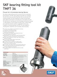
Cause of bearing failureBecause the non-locating bearing needsa loose fit on its seat to accommodate axialexpansion and contraction of the shaft, theloose fit must be maintained during operation.Maintaining this loose fit is not as simpleas it might seem and can be restricted for anyof the following reasons:• During start-up, as machine componentsare warming up, the outer ring of a bearingusually expands faster than the housingbore. This difference in the rate of expansioncan eliminate the loose fit betweenthe bearing and its seat to restrict axialmovement.• If the form of the bearing seat in the housingis not within specification, the bearingring will be held in place and will be unableto move axially. This can be due to an ovalor tapered seat, or, more commonly, a distortedseat that results when the base supportis not sufficiently flat or rigid.• Under unfavourable load conditions, a loosering can create a condition known as frettingcorrosion, which can effectively “rust”the bearing ring in place.• Wear of the bearing seat can also locatethe bearing.If the bearing in the non-locating positioncannot move smoothly or is restricted frommoving on its seat to accommodate thermalexpansion and contraction of the shaft, bothbearings will be subjected to heavy inducedaxial loads († fig. 2). <strong>The</strong> effects of theseadditional induced axial loads will be seen ashigh bearing temperatures, excessive vibration,increased lubricant usage and ultimatelypremature bearing failure.Heavy axial loads and stresses are induced in the bearings systemif the non-locating bearing is restricted from axial motionF rFig. 25
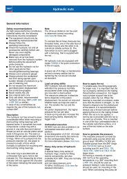
A typical example of shaftexpansion and its effectsDiagram 1 shows temperature readings takenat the outer ring of an oil-lubric ated sphericalroller bearing in the non-locating position ona paper machine roll, during the machinestart -up period.<strong>The</strong> diagram clearly shows that frictionbetween the bearing outer ring and the housingseat does exist and that it significantlyaffects the amount of heat generated by thebearing. As operating temperatures increaseand the shaft starts to expand, the temperaturewithin the bearing also increases untilfrictional resistance is overcome and there isa sudden movement of the bearing, characterizedby a noticeable decrease in the temperature.This phenomena, known as stickslip, will continue until the shaft reaches normaloperating temperature. Even after themachine has reached its normal operatingtemperature, it is likely that there will be someresidual induced axial loading on the bearingsto cause an uneven load distribution betweenthe roller sets.<strong>The</strong> process will repeat (in reverse) with anydecrease in temperature of the shaft or structuredue to a change in process parameters,e.g. idling.Note that for <strong>SKF</strong> “CC” and “E” type spher -ical roller bearings, the ratio of axial load toradial load must be quite high (15 % or more)before there is a significant increase in thetotal rolling friction inside the bearing (totalfriction = load-dependent friction + viscousfriction from the lubricant). <strong>The</strong>refore, forbearings under nominally pure ra dial load,there must be a significant axial force resultingfrom friction between the bearing outerring and housing seat in order for temperaturevariations such as those in the diagramto be noticeable. <strong>The</strong> fact that a change intemperature is easily measured shows thatthe acting friction factor is > 0,1.Diagram 1Axial position of the outer ring and corresponding bearing temperature during start-upTemperatureOuter ring axial positionTime7
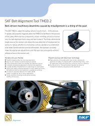
Axial force over time –characteristic examples<strong>The</strong> magnitude of the induced axial loads ina traditional self-aligning bearing system canvary depending on a number of largely unpredictableparameters. <strong>The</strong>se parameters, whichdetermine the average force and averageequivalent friction factor over the life of thebearing system, include• the initial radial clearance in each bearingafter mounting• the axial offset of the inner and outer ringsof each bearing after mounting• the magnitude of the radial load on thebearing in the non-locating position• the nature of the radial load on the bearingin the non-locating position (steady or fluctuating,uni-directional or random)• vibration levels from external sources• surface finish of the bearing and housingseat contact surfaces (non-locating positiononly)• lubrication conditions between the contactzone of the bearing in the non-locatingposition and its seat in the housing• looseness of the fit (individual diametricaltolerances of the bearing in the non-locatingposition and its seat in the housing)• form tolerance of the non-locating bearingseat (ovality and taper)• distortion of the non-locating seat underload• distortion of the non-locating bearingseat with thermal changes• relative rate of thermal axial expansion(contraction) of rotating and stationarycomponents (shaft and structure)• relative rate of thermal radial expansion(contraction) of outer ring of the nonlocatingbearing and its seat• axial stiffness of the supporting structure.Greater internal clearance within the bearingwill reduce the impact of heavy induced axialloads. However, excessive clearance alsomeans that fewer rolling elements carry theload. Typically this will result in a decrease inbearing fatigue life and increase the risk ofpoor operating conditions within the bearings.In the examples below, it is assumed thatthe shaft expands in relation to the structure.Without very precise tolerances and painstakingmeasurements during assembly, it isimpossible to know what will actually occurwith any individual machine.Diagram 2Diagram 3Small initial axial clearance (rings centred at mounting)– start-up periodInduced axial load/radial load<strong>Bearing</strong> jammed in the housing1,5Induced axial load/radial loadSteady-state operationwith heavy axial loads0,20,1Steady state10,5Non-locating bearingjammed in the housing00TimeInitially axial clearanceTime8
<strong>The</strong> <strong>SKF</strong> self-aligning bearing systemNot so long ago, compromise was a part ofevery bearing system that had to accommodateaxial expansion of the shaft. <strong>The</strong> toroidalroller bearing developed by <strong>SKF</strong> changed that.Today, with a toroidal roller bearing in thenon-locating bearing position and a selfaligningball bearing or a spherical rollerbearing in the locating position, machinedesigners can optimize their application andprovide more value to their customers withimproved reliability and increased service life.<strong>The</strong> toroidal roller bearing got its namefrom the form of the curvature at the contactsurfaces within the bearing. <strong>The</strong> toroidal rollerbearing has a single row of long rollers witha slightly curved profile. <strong>The</strong> internal designenables the bearing to accommodate axialdisplacement within the bearing, like a cylindricalor needle roller bearing, virtually withoutfriction, avoiding the problem of inducedaxial loads. This eliminates the need fora loose fit for either of the bearing rings(† fig. 1).In addition to eliminating the axial interactionbetween the bearings, the roller andraceway profiles in the toroidal roller bearingare designed to automatically adjust the positionof the rollers inside the bearing so thatthe load is distributed evenly along the rollercontact length, irrespective of any misalignment.This also avoids high edge stresses, sothe bearing operates at the optimum stresslevel, and therefore achieves its theoret icalfatigue life under all conditions († fig. 2).<strong>The</strong> combination of the self-aligning propertiesand the almost frictionless axial displacementwithin the bearing, distributesthe load evenly and consistently between therows of rolling elements in both bearings inthe system. <strong>The</strong> actual load distribution willdepend on the externally applied radial andaxial loads. An optimized load distributionmeans that stresses are low, temperature isminimized, maximum fatigue life is achieved,and the chance of vibration and cage damageare reduced. In addition, because tight fits canbe used for all bearing rings in the system, therisk of housing damage due to ring creep canbe eliminated († fig. 3).<strong>The</strong> position of therollers in a toroidalroller bearing isautomatically adjustedand the load is distributedevenly along theentire roller length<strong>The</strong>re are no inducedaxial loads, this ensureseven load distributionin both bearingsF rFig. 1When using a toroidal roller bearing there isno induced axial loadnormal twisted ring misaligned axially displacedF rPlease note that when using a CARB bearing, the outerring of the non-locating bearing must also be fixed!Fig. 2Fig. 39
<strong>SKF</strong> toroidal roller bearing<strong>The</strong> toroidal roller bearing was introduced by<strong>SKF</strong> in 1995. Known as a CARB bearing, thebearing is available in a range of ISO DimensionSeries, equivalent to self-aligning ballbearings and spherical roller bearings usedin stand ard bearing housings and other commontypes of bearing assemblies. <strong>The</strong> rangealso covers wide, low section series equivalentto needle roller bearings († fig. 4).A CARB bearing enables machine manufacturersand users to optimize bearing systems,simply by substituting the current bearing inthe non-locating position with a dimensionallyequivalent toroidal roller bearing. <strong>The</strong> bearingin the locating position remains the same asdoes other standard components like housings,adapter sleeves etc.Low load performanceIn addition to functioning well under heavyradial loads, CARB toroidal roller bearingsalso perform very well when subjected tolight loads. <strong>The</strong> minimum radial load isimportant because it enables the rollersto operate smoothly and minimize fatigue.A minimum load also reduces the risk ofroller and raceway smearing, cage hammering,vibration, grease degradation andexcessive temperature. Proper minimumload requirements can be pre-determinedbased on the size of the rolling elements,rotational speeds, and lubricant viscosity.In a spherical roller bearing that operatesunder a purely radial load, both rows ofrollers share the load equally. (necessaryradial load factor = 1 from diagram 1).In applications where radial loads areaccompanied by axial loads that alter theposition of one bearing ring relative to theother, the load distribution changes resultingin a reduced load on one row of rollers.Consequently, in order to maintain sufficientminimum load on the least loaded rowof rollers, the total radial load on the bearingmust be increased (i.e. multiplied by aradial load factor, † diagram 1) for a givenfriction factor μ between the outer ring andhousing when axial displacement occurs( given ratio of axial to radial load). Diagram 1shows the calculation factor e for sphericalroller bearings provided in tables of the <strong>SKF</strong>General Catalogue. <strong>The</strong> factor e varies between0,15 and 0,40, depending on the bearingcontact angle.In a conventional self-atigning bearing systemcontaining two spherical roller bearings,friction between the non-locating bearingouter ring and its housing seat leads to lessthan optimal load distribution. As a result, theradial load required for satisfactory operationmust be drastically increased to compensatefor the added friction. However, there arelimits. When the equivalent friction factorof the bearing in the non-locating positionapproaches 0,89 it is not possible to adequatelyload the bearings.When externally applied radial loads areplaced on a toroidal roller bearing, both rowsof rollers in the locating bearing should alwaysbe equally loaded. <strong>The</strong>refore, the radial loadfactor to be used to determine the appliedload required to achieve satisfactory operationis always equal to 1 as described in diagram 1.Fig. 4CARB bearings are availablein various ISO DimensionSeries10
Diagram 15Radial load factor∞43Conventional selfaligningbearingsystem21<strong>SKF</strong> self-aligning bearing systemRequired radial loadfor smooth operationof a conventionalself-aligning bearingsystem with twospherical rollerbearings, as a functionof housing friction00 0,25 0,5 0,75 0,89 1me11
Improving operatingconditions and reliabilityFollowing are three examples where the <strong>SKF</strong>self-aligning bearing system was able to provideimmediate operational improvements,by enhancing internal load distributionbetween the locating and non-locating bearings.<strong>The</strong> first case († diagrams 2 and 3) isa very large axial flow fan originally equippedwith 22244/C3W33 spherical roller bearingsin both positions († diagram 2). <strong>The</strong> bearingin the non-locating position was replaced bya dimensionally identical toroidal roller bearing(C 2244/C3). <strong>The</strong> result was the eliminationof the high vibration peaks and an almostimmediate stabilization of bearing temperaturesto approximately 20 °C above ambient(† diagram 3).Fan with a 22244 CC/C3W33 spherical roller bearing at both positionsVibration, mm/sTemperature200Vibration12,010,08,06,04,02,00,00 0,5 1 1,5 2 2,5 3 3,5HoursDiagram 2Temperature riseabove ambient, °C6040Diagram 3<strong>The</strong> same fan with a C 2244/C3 toroidal roller bearing at the non-locating positionVibration, mm/sTemperature riseabove ambient, °CTemperature20,000,60,40,2Vibration00 0,5 1,0 1,5 2,0Hours12
Diagram 4Industrial fan rebuilt with a C 2216 K toroidal roller bearing. Grease lubrication, 3 000 r/min<strong>Bearing</strong> temperature increase above ambient16°C12°C9°CTwo other cases of rebuilt industrial fansare shown in diagrams 4 and 5. Both examplesare conventional centrifugal fans wherethe spherical roller bearing in the non-locatingposition was replaced by a toroidal rollerbearing of the same size.In both fans, the operating temperatureof the bearing in the non-locating positiondropped dramatically. <strong>The</strong> temperature ofthe bearing in the locating position was alsoreduced but to a lesser extent. This is expected,as the bearing in the locating position mustcarry some axial load from the fan impellerand should therefore run somewhat hotterthan the bearing in the non-locating position.4°C22216 EK + 22216 EK 22216 EK + C 2216 KDiagram 5Industrial fan rebuilt with a C 2216 toroidal roller bearing. Oil lubrication, 3 000 r/min<strong>Bearing</strong> temperature increase above ambient26 °C26 °C18 °C12 °C22216 E + 22216 E 22216 E + C 221613
Reducing costsby downsizingPerformance enhancements and productivityimprovements are not the only benefits thatcan be realized by using the <strong>SKF</strong> self-aligningbearing system. When a CARB toroidal rollerbearing is in the non-locating position, theinduced axial load, F a , equals zero for bothbearings. In a conventional self-aligning bearingsystem, induced axial loads within bothbearings must be calculated using the formula(F a = F r ¥ m). Once these forces are realized,it is a simple matter to calculate the differencein fatigue life obtained in each bearing system.In applications where the life of a conventionalself-aligning bearing system restricts performance,substituting the non-locating bearingwith a toroidal roller bearing can significantlyextend service life.In instances where a conventional selfaligningbearing system provides adequateservice life, it is possible, in many cases, todownsize the application using the <strong>SKF</strong> selfaligningbearing system and still achieve therequired life († diagram 6). This possibilityoffers designers significant opportunitiesto use smaller, more cost-effective bearingassemblies without the risks associated withinduced axial loads. This bearing system,which features a CARB toroidal roller bearing,also enables designers to reduce the size andweight of associated structural components.Benefits of the <strong>SKF</strong> self-aligning bearingsystem includeLight loads, high speedsIn high speed applications, with light loadsand where misalignment can be expected,self-aligning ball bearings in both the locatingand non-locating positions have been thestandard solution. However, many of thesehigh speed applications generate enough heatthat axial expansion and contraction of theshaft can be a major concern. For these applications,toroidal roller bearings can providegreat benefits for all the same reasons thatwere described earlier. Because self-aligningball bearings are much more susceptible todamage from axial preloading than sphericalroller bearings, the possibility of friction-inducedaxial loads leading to premature bearingfailure can be virtually eliminated whentoroidal roller bearings are used in the nonlocatingbearing position († diagram 7).<strong>The</strong> <strong>SKF</strong> self-aligning bearing system can give better life even with smaller bearings11,20C 3148Diagram 623148 CC/W33• reduced cost and weight of the bearingassembly• reduced size, length, cost and weightof the shaft• reduced size and weight of the supportstructure 1)• less stringent machining and assemblytolerances 1)• reduced transportation costs resulting fromdecreased machine weight.Relative L 10 life for bearing systemdownsizing0,700,37C 314423144 CC/W3323148 CC/W33 23148 CC/W331) As there is no risk of cross-location of the bearings dueto the frictionless internal axial displacement in a CARBbearing, there is less importance placed upon the formand rigidity of the supporting structure for the bearings,meaning that lighter, more flexible and less precisecomponents can be tolerated without a correspondingreduction in bearing performance000,05 0,1 0,15*) 0,2 0,25 0,3 0,35 0,4Friction coefficient µ*) µ = 0,15 for steel against cast iron14
Eliminating the risk ofpoor operating conditions<strong>The</strong> diagrams showing the life of comparativebearing systems († diagrams 6 and 7) aresimplifications.<strong>The</strong> calculations assume that there is noexternal axial load on the shaft system, andthat both bearings carry nominally radialloads (such as a belt conveyor pulley, papermachine roll, continuous caster roll, table roll).<strong>The</strong> axial forces used to determine the L 10fatigue life are then only those generatedwithin the bearing system itself.Should there really be external axial forces(often the case), then the difference betweenthe calculated life of the two types of bearingsystems will be reduced; the slope of thecurve for the conventional arrangement willbe less, sometimes appreciably so. Nevertheless,the same principle applies, in that theconventional bearing arrangement will stillexperience some variation of the internal loaddistribution due to internally induced forces,in addition to the nominal externally appliedloads, whereas the <strong>SKF</strong> self-aligning bearingsystem will not.For any specific case, it is almost impossibleto know what the equivalent “average” valueof m will be over the life of the bearing system(i.e. which position on the x-axis of the graphis relevant). As seen earlier, there are an infinitenumber of combinations involving bearingclearance, initial offset, housings boretolerance and condition, etc.Some machines may operate with a low“average” m, but there is always a significantchance that an individual machine may havea high average m for any number of unquantifiablereasons.<strong>The</strong> <strong>SKF</strong> self-aligning bearing system, witha toroidal roller bearing in the non-locatingposition, eliminates the possibility of the highm factor, as by definition m is always equal tozero.Diagram 7<strong>The</strong> compromise-freesolutionWith the <strong>SKF</strong> self-aligning bearing system,utilizing a CARB toroidal roller bearing in thenon-locating position, the many excellentdesign features and operating capabilitiesof <strong>SKF</strong> spherical roller and self-aligning ballbearings can now be fully exploited. With thisbearing system, design engineers will be ableto optimize their designs and provide customerswith the most reliable solution possible.<strong>System</strong> life comparison for self-aligning ball bearings6544,92222 MC 2222Relative L 10 life for bearing system322,22220 MC 2220Note<strong>Bearing</strong> system fatigue life = L 10, sys10,451 1 1——— = ——— + –————(L 10, sys ) e (L 10, loc ) e (L 10, non-loc ) e002222 M 2222 M0,05 0,1 0,15 *) 0,2 0,25 0,3 0,35 0,4Friction coefficient µFor roller bearings, e = 9/8For ball bearings, e = 10/9*) µ = 0,15 for steel against cast iron15
Less risk ofunderloadingEven and consistentloaddistributionLow cageforcesReducedcagefailureNo axialvibrationLongergreaselifeNovibrationImprovementswith the <strong>SKF</strong>self aligning bearingsystem (axialfreedom)Tight fitpossibleReducedmaintenancecostsNohousingwearLower componentcostsLowerfrictionIncreasedproduct ivityElimination ofaxial forcesEvenloaddistributionLowstresslevelsIncreasedfatigue lifeReducedmaintenanceDownsizedbearings16
Increasedgrease lifeIncreasedproductivityReducedmaintenanceLess risk ofsmearingImprovedbearingreliabilityLower greasecostLowergreasecostLow noiseReducedmaintenanceIncreasedproductivityReducedvibrationGeneralmachineimprovementLower rejectcostsImprovedproduct qualityIncreasedproductivityReducedtemperatureImprovedlubricantfilmthicknessLowergreasecostLongergreaselifeReducedmaintenanceLess riskof cagefailureIncreasedproduct -ivityLowerpowerusageLessrisk ofsmearingImprovedbearingreliabilityIncreasedproduct -ivityIncreasedgreaselifeReducedmaintenanceLowerpriceReducedvibrationLowernoiseIncreasedproductqualityGeneralmachineimprovementLowerrejectcostsReducedmaintenanceReducedwearNo riskof underloadingReducedtemp era -tureLongergreaselifeLowergreasecostLowfrictionLowerpowerusageImprovedlubricantfilmthicknessImprovements with the <strong>SKF</strong> selfaligningbearing system17
OperatingconditionsTypicalapplicationsTemperaturereductionVibration andnoise reductionHousing or shaftwear reductionImproved reliability to eliminatecatastrophic failuresHeavy loadLow speedWheelContinuous castersScrew conveyorsGrinding millsPress rollsGear shafts····Medium to heavyloadMedium to highspeedDrying cylindersConveyor pulleysRoller tablesCalandersCrushersPropulsion equipmentFlour millsGear shaftsFelt rollsWire rolls·· ·· ····Light loadHigh speedIndustrial fansBlowersAgricultural machineryGear shaftsSction rolls··· ·· ·· ···Eccentric motionCetrifugal loadsVibrating screenWashing machineryCrank press·· ··· ···IndeterminateloadsMedium to highspeedShreddersChippersIndustrial lawn mowersLarge electric motorsCrushersBlowersMixersHarvestersPumps·· · ··· ··Heated rotorsLarge thermalexpansionPaper dryersHeated calendersCookersMixersYankee drying cylindersHeat exchangers··· ·No influence: – Little influence: · Some influence: ·· Strong influence: ···18
ReducedmaintenanceIncreasedthroughputDecreasedstopping timeIncrease L 10 lifeor downsizeSimpler cheaperstructureSimpler installationprocedure·· · ··· ·· ··· · ·· ·· ····· ··· · ···· ·· ·· ····· · ·· · · ···· ·· ·· ··· ··· ···Influences of the <strong>SKF</strong> self-aligning bearing system for different types of machines19
<strong>SKF</strong> – the knowledgeengineering companyFrom the company that invented the selfaligningball bearing more than 100 yearsago, <strong>SKF</strong> has evolved into a knowledge engineeringcompany that is able to draw on fivetechnology platforms to create unique solutionsfor its customers. <strong>The</strong>se platformsinclude bearings, bearing units and seals, ofcourse, but extend to other areas including:lubricants and lubrication systems, critical forlong bearing life in many applications; mechatronicsthat combine mechanical and electronicsknowledge into systems for more effectivelinear motion and sensorized solutions; anda full range of services, from design and logisticssupport to conditioning monitoring andreliability systems.Though the scope has broadened, <strong>SKF</strong>continues to maintain the world’s leadershipin the design, manufacture and marketing ofrolling bearings, as well as complementaryproducts such as radial seals. <strong>SKF</strong> also holdsan increasingly important position in the marketfor linear motion products, high-precisionaerospace bearings, machine tool spindlesand plant maintenance services.<strong>The</strong> <strong>SKF</strong> Group is globally certified to ISO14001, the international standard for environmentalmanagement, as well as OHSAS18001, the health and safety managementstandard. Individual divisions have been approvedfor quality certification in accordancewith either ISO 9001 or ISO/TS 16949.With some 100 manufacturing sites worldwideand sales companies in 70 countries,<strong>SKF</strong> is a truly international corporation. Inaddition, our distributors and dealers insome 15 000 locations around the world,an e-business marketplace and a global distributionsystem put <strong>SKF</strong> close to customers forthe supply of both products and services. Inessence, <strong>SKF</strong> solutions are available whereverand whenever customers need them. Overall,the <strong>SKF</strong> brand and the corporation arestronger than ever. As the knowledge engineeringcompany, we stand ready to serveyou with world-class product competencies,intellectual resources, and the vision to helpyou succeed.© Airbus – photo: e x m company, H. GousséEvolving by-wire technology<strong>SKF</strong> has a unique expertise in fast-growing by-wiretechnology, from fly-by-wire, to drive-by-wire, towork-by-wire. <strong>SKF</strong> pioneered practical fly-by-wiretechnology and is a close working partner with allaerospace industry leaders. As an example, virtuallyall aircraft of the Airbus design use <strong>SKF</strong> by-wiresystems for cockpit flight control.<strong>SKF</strong> is also a leader in automotive by-wire technology,and has partnered with automotive engineers todevelop two concept cars, which employ <strong>SKF</strong> mechatronicsfor steering and braking. Further by-wiredevelopment has led <strong>SKF</strong> to produce an all-electricforklift truck, which uses mechatronics rather thanhydraulics for all controls.Seals<strong>Bearing</strong>sand unitsLubricationsystemsMechatronicsServices20
Harnessing wind power<strong>The</strong> growing industry of wind-generated electric power provides a source ofclean, green electricity. <strong>SKF</strong> is working closely with global industry leaders todevelop efficient and trouble-free turbines, providing a wide range of large, highlyspecialized bearings and condition monitoring systems to extend equipment lifeof wind farms located in even the most remote and inhospitable environments.Working in extreme environmentsIn frigid winters, especially in northern countries, extreme sub-zero temperaturescan cause bearings in railway axleboxes to seize due to lubrication starvation.<strong>SKF</strong> created a new family of synthetic lubricants formulated to retain theirlubrication viscosity even at these extreme temperatures. <strong>SKF</strong> knowledge enablesmanufacturers and end user customers to overcome the performance issuesresulting from extreme temperatures, whether hot or cold. For example, <strong>SKF</strong>products are at work in diverse environments such as baking ovens and instantfreezing in food processing plants.Developing a cleaner cleaner<strong>The</strong> electric motor and its bearings are the heart of many household appliances.<strong>SKF</strong> works closely with appliance manufacturers to improve their products’ performance,cut costs, reduce weight, and reduce energy consumption. A recentexample of this cooperation is a new generation of vacuum cleaners with substantiallymore suction. <strong>SKF</strong> knowledge in the area of small bearing technologyis also applied to manufacturers of power tools and office equipment.Maintaining a 350 km/h R&D labIn addition to <strong>SKF</strong>’s renowned research and development facilities in Europe andthe United States, Formula One car racing provides a unique environment for<strong>SKF</strong> to push the limits of bearing technology. For over 50 years, <strong>SKF</strong> products,engineering and knowledge have helped make Scuderia Ferrari a formidableforce in F1 racing. (<strong>The</strong> average racing Ferrari utilizes more than 150 <strong>SKF</strong> components.)Lessons learned here are applied to the products we provide to automakersand the aftermarket worldwide.Delivering Asset Efficiency OptimizationThrough <strong>SKF</strong> Reliability <strong>System</strong>s, <strong>SKF</strong> provides a comprehensive range of assetefficiency products and services, from condition monitoring hardware and softwareto maintenance strategies, engineering assistance and machine reliabilityprogrammes. To optimize efficiency and boost productivity, some industrial facilitiesopt for an Integrated Maintenance Solution, in which <strong>SKF</strong> delivers all servicesunder one fixed-fee, performance-based contract.Planning for sustainable growthBy their very nature, bearings make a positive contribution to the natural environment,enabling machinery to operate more efficiently, consume less power,and require less lubrication. By raising the performance bar for our own products,<strong>SKF</strong> is enabling a new generation of high-efficiency products and equipment.With an eye to the future and the world we will leave to our children, the<strong>SKF</strong> Group policy on environment, health and safety, as well as the manufacturingtechniques, are planned and implemented to help protect and preserve theearth’s limited natural resources. We remain committed to sustainable, environmentallyresponsible growth.21
® <strong>SKF</strong> and CARB are registered trademarks of the <strong>SKF</strong>Group.© <strong>SKF</strong> Group 2008<strong>The</strong> contents of this publication are the copyright of thepublisher and may not be reproduced (even extracts)unless permission is granted. Every care has been takento ensure the accuracy of the information contained in thispublication but no liability can be accepted for any loss ordamage whether direct, indirect or consequential arisingout of the use of the information contained herein.Publication 6121 EN · March 2008This publication supersedes publication 4417/II E.Printed in Sweden on environmentally friendly paper.skf.com