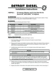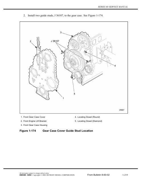
2. Install two guide studs, J 36107, to the gear case. See ... - ddcsn
2. Install two guide studs, J 36107, to the gear case. See ... - ddcsn
2. Install two guide studs, J 36107, to the gear case. See ... - ddcsn

You also want an ePaper? Increase the reach of your titles
YUMPU automatically turns print PDFs into web optimized ePapers that Google loves.
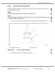
1.10 GEAR CASE COVER[c] <strong>Install</strong> <strong>the</strong> front engine mount <strong>to</strong> <strong>the</strong> <strong>gear</strong> <strong>case</strong> cover. <strong>Install</strong> <strong>the</strong> four, longer, frontengine mount-<strong>to</strong>-<strong>gear</strong> <strong>case</strong> cover bolts, finger-tight.[d] Torque bolts 17, 18, 19 and 20 <strong>to</strong> 160-200 N·m (118-148 lb·ft). <strong>See</strong> Figure 1-175.[e] Bolts F1 through F5 are fan support bracket bolts. <strong>Install</strong> <strong>the</strong> fan support bracket and<strong>to</strong>rque bolts F1, F2 and F3 <strong>to</strong> 58-73 N·m (43-54 lb·ft). Torque bolts F4 and F5 <strong>to</strong>160-200 N·m (118-148 lb·ft).[f] <strong>Install</strong> <strong>the</strong> six bolts on <strong>the</strong> intake (left) side of <strong>the</strong> engine around <strong>the</strong> aircompressor drive. Torque <strong>the</strong> bolts <strong>to</strong> 58-73 N·m (43-54 lb·ft), using <strong>the</strong> sequence.<strong>See</strong> Figure 1-176.Figure 1-176Air Compressor Drive Torque Sequence[g] <strong>Install</strong> <strong>the</strong> SRS <strong>to</strong> <strong>the</strong> <strong>gear</strong> <strong>case</strong>; refer <strong>to</strong> section <strong>2.</strong>29.3.All information subject <strong>to</strong> change without notice.1-222 From Bulletin 8-60-02 6SE483 0204 Copyright © 2002 DETROIT DIESEL CORPORATION
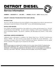
SERIES 60 SERVICE MANUAL[h]<strong>Install</strong> <strong>the</strong> <strong>two</strong> rear mounted bolts (pre - 1991 engines only) bolts on <strong>the</strong> exhaust(right) side of <strong>the</strong> engine. Torque <strong>the</strong> number 2 and 3 bolts <strong>to</strong> 58-73 N·m(43-54 lb·ft) <strong>to</strong>rque. <strong>See</strong> Figure 1-177.Figure 1-177Gear Case Cover Bolt Torque Sequence (Right Rear)7. <strong>Install</strong> a new crankshaft front oil seal. Refer <strong>to</strong> section 1.8.7.8. <strong>Install</strong> <strong>the</strong> accessory drive assembly <strong>to</strong> <strong>the</strong> <strong>gear</strong> <strong>case</strong>. Refer <strong>to</strong> section 1.28.5.9. <strong>Install</strong> <strong>the</strong> vibration damper <strong>to</strong> <strong>the</strong> crankshaft. Refer <strong>to</strong> section 1.1<strong>2.</strong>3.10. <strong>Install</strong> <strong>the</strong> crankshaft pulley <strong>to</strong> <strong>the</strong> end of <strong>the</strong> crankshaft. Refer <strong>to</strong> section 1.13.3.11. <strong>Install</strong> <strong>the</strong> water pump assembly. Refer <strong>to</strong> section 4.<strong>2.</strong>8 for <strong>gear</strong> <strong>case</strong> mounted.Refer <strong>to</strong> section 4.3.7 for front mounted.1<strong>2.</strong> <strong>Install</strong> a new gasket between <strong>the</strong> power steering pump cover and <strong>the</strong> <strong>gear</strong> <strong>case</strong> (if soequipped).13. <strong>Install</strong> <strong>the</strong> power steering pump cover <strong>to</strong> <strong>the</strong> <strong>gear</strong> <strong>case</strong> cover with <strong>the</strong> six bolts. Tighten <strong>the</strong>bolts progressively in a star-shaped pattern <strong>to</strong> draw <strong>the</strong> power steering pump in evenly.Torque <strong>the</strong> bolts <strong>to</strong> 30-38 N·m (22-28 lb·ft), using a star-shaped pattern.14. Insert a new gasket between <strong>the</strong> camshaft drive <strong>gear</strong> access cover and <strong>the</strong> <strong>gear</strong> <strong>case</strong> cover.All information subject <strong>to</strong> change without notice.6SE483 0204 Copyright © 2002 DETROIT DIESEL CORPORATION From Bulletin 8-60-02 1-223
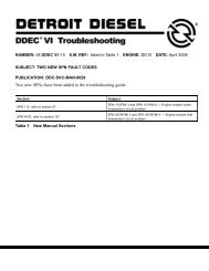
1.10 GEAR CASE COVER15. <strong>Install</strong> <strong>the</strong> camshaft drive <strong>gear</strong> access cover <strong>to</strong> <strong>the</strong> <strong>gear</strong> <strong>case</strong> cover. Torque <strong>the</strong> bolts <strong>to</strong>30-38 N·m (22-28 lb·ft), using <strong>the</strong> tightening sequence. <strong>See</strong> Figure 1-178.Figure 1-178Access Cover Bolt Torque Sequences16. <strong>Install</strong> <strong>the</strong> air conditioner compressor and brackets. <strong>Install</strong> <strong>the</strong> air conditioner compressordrive belt. Refer <strong>to</strong> OEM <strong>guide</strong>lines.17. <strong>Install</strong> <strong>the</strong> alterna<strong>to</strong>r and brackets. Refer <strong>to</strong> section 8.<strong>2.</strong>3. <strong>Install</strong> <strong>the</strong> alterna<strong>to</strong>r drivebelts. Refer <strong>to</strong> section 13.13.10.18. Adjust <strong>the</strong> alterna<strong>to</strong>r and air conditioner compressor drive belts <strong>to</strong> <strong>the</strong> specifications.Refer <strong>to</strong> section 13.13.10.19. <strong>Install</strong> <strong>the</strong> engine oil pan. Refer <strong>to</strong> section 3.11.4. Fill <strong>the</strong> crank<strong>case</strong> with recommendedlubricating oil. Refer <strong>to</strong> section 13.13.1.All information subject <strong>to</strong> change without notice.1-223a From Bulletin 8-60-02 6SE483 0204 Copyright © 2002 DETROIT DIESEL CORPORATION
SERIES 60 SERVICE MANUALThis page intentionally left blank.All information subject <strong>to</strong> change without notice.6SE483 0204 Copyright © 2002 DETROIT DIESEL CORPORATION From Bulletin 8-60-02 1-223b
1.10 GEAR CASE COVER1.10.4 <strong>Install</strong>ation of Acoustical Gear Case Covers<strong>Install</strong> acoustical covers as outlined below. <strong>See</strong> Figure 1-179, and see Figure 1-180, for GroupA installations with accessory drive. <strong>See</strong> Figure 1-181 and see Figure 1-182for installation onGroup B without accessory drive. <strong>See</strong> Figure 1-183 and see Figure 1-184for typical Group Cinstallations. <strong>See</strong> Figure 1-185 and see Figure 1-186for Group D installations.1. Using required fasteners, install front <strong>gear</strong> <strong>case</strong> acoustical cover and accessory driveacoustical cover. Tighten bolts and nut(s) <strong>to</strong> <strong>the</strong> <strong>to</strong>rque values: listed in Table 1-4.<strong>2.</strong> Using required fasteners and clips, install right rear and left rear covers. Tighten bolts andnut(s) <strong>to</strong> <strong>the</strong> <strong>to</strong>rque values listed in Table 1-4.Bolt or Nut SizeM6 x 1.0M8 x 1.25M10 x 1.5Required Torque13-16 N·m (10-12 lb·ft)30-38 N·m (22-28 lb·ft)58-73 N·m (43-54 lb·ft)Table 1-4Acoustical Cover Fastener Torque ValuesAll information subject <strong>to</strong> change without notice.1-224 From Bulletin 8-60-02 6SE483 0204 Copyright © 2002 DETROIT DIESEL CORPORATION