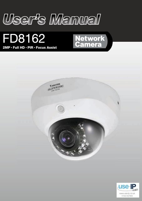
Vivotek FD8162 Fixed Dome Network Camera User Manual - Use-IP
Vivotek FD8162 Fixed Dome Network Camera User Manual - Use-IP
Vivotek FD8162 Fixed Dome Network Camera User Manual - Use-IP
- No tags were found...

Create successful ePaper yourself
Turn your PDF publications into a flip-book with our unique Google optimized e-Paper software.
<strong>FD8162</strong>2MP • Full HD • PIR • Focus Assist
VIVOTEKTable of ContentsOverview4Read Before <strong>Use</strong> 5Package Contents 5Symbols and Statements in this Document 5Physical Description 6Hardware Installation 7<strong>Network</strong> Deployment 10Software Installation 12Ready to <strong>Use</strong> 13Accessing the <strong>Network</strong> <strong>Camera</strong> 16Using Web Browsers 16Using RTSP Players 18Using 3GPP-compatible Mobile Devices 19Using VIVOTEK Recording Software 20Main Page 21Client Settings 26Configuration 28System > General settings 29System > Homepage layout 31System > Logs 34System > Parameters 35System > Maintenance 36Security > <strong><strong>Use</strong>r</strong> Account 40Security > HTTPS (Hypertext Transfer Protocol over SSL) 41Security > Access List 46<strong>Network</strong> > General settings 51<strong>Network</strong> > Streaming protocols 59<strong>Network</strong> > SNMP (Simple <strong>Network</strong> Management Protocol) 68Media > Image 69Media > Video 78Media > Audio82PTZ > PTZ settings 83Event > Event settings 86Applications > Motion detection99Applications > DI and DO 102Applications > Tampering detection 102Recording > Recording settings 103Local storage > SD card management 108Local storage > Content management 109Appendix 111URL Commands for the <strong>Network</strong> <strong>Camera</strong> 1112 - <strong><strong>Use</strong>r</strong>'s <strong>Manual</strong>
VIVOTEKTechnical Specifications 179Technology License Notice 180Electromagnetic Compatibility (EMC) 181<strong><strong>Use</strong>r</strong>'s <strong>Manual</strong> - 3
VIVOTEKRead Before <strong>Use</strong>The use of surveillance devices may be prohibited by law in your country The <strong>Network</strong> <strong>Camera</strong> is notonly a high-performance web-ready camera but can also be part of a flexible surveillance system. It isthe user’s responsibility to ensure that the operation of such devices is legal before installing this unit forits intended useIt is important to first verify that all contents received are complete according to the Package Contentslisted below Take note of the warnings in the Quick Installation Guide before the <strong>Network</strong> <strong>Camera</strong> isinstalled; then carefully read and follow the instructions in the Installation chapter to avoid damage due tofaulty assembly and installation This also ensures the product is used properly as intendedThe <strong>Network</strong> <strong>Camera</strong> is a network device and its use should be straightforward for those who have basicnetworking knowledge It is designed for various applications including video sharing, general security/surveillance, etc The Configuration chapter suggests ways to best utilize the <strong>Network</strong> <strong>Camera</strong> andensure proper operations For creative and professional developers, the URL Commands of the <strong>Network</strong><strong>Camera</strong> section serves as a helpful reference to customizing existing homepages or integrating with thecurrent web serverPackage Contents■ <strong>FD8162</strong> - the <strong>Network</strong> <strong>Camera</strong>■ Alignment Sticker■ T10 Torx screwdriver / Screws / Plastic anchors■ DC Power Cable■ Quick Installation Guide / Warranty Card■ Software CDSymbols and Statements in this Documenti INFORMATION:provides important messages or advices that might help prevent inconvenientor problem situationsNOTE: Notices provide guidance or advices that are related to the functional integrity of themachineTips: Tips are useful information that helps enhance or facilitae an installation, function, orprocessWARNING! or IMPORTANT!: These statements indicate situations that can be dangerous orhazardous to the machine or youElectrical Hazard: This statement appears when high voltage electrical hazards might occurto an operator<strong><strong>Use</strong>r</strong>'s <strong>Manual</strong> - 5
VIVOTEKPhysical Description<strong>Camera</strong> Front ViewLight SensorLensBlack CoverIR LEDs(18 units, effective upto 15m)Focus AssistButton<strong>Camera</strong> Rear ViewBuilt-inMicrophonePIR SensorReservedMicro SD/SDHCCard SlotReset ButtonJumpersMicrophone Video OutputNTSCinternal60HzReset Micro SD CardInt Int IntNTSCAV Out Audio InPALExtEthernet1234 5678externalPAL50Hz1 2Audio/Video OutAudio In10/100BaseTGeneral I/O Terminal BlockEthernetGeneral IO TerminalBlockThis <strong>Network</strong> <strong>Camera</strong> provides a general I/O terminal block which is used to connect externalinput / output devices. The pin definitions are described below.12345678PinName1 DC 12V-2 DC 12V+3 AC 24V_24 AC 24V_15 DI- (GND)6 DI+7 DO-8 DO+ (+12V)6 - <strong><strong>Use</strong>r</strong>'s <strong>Manual</strong>
VIVOTEKHardware InstallationBefore installing your camera, makesure the built-in PIR (Passive InfraredSensor) can be directed toward thearea of interest, where possibleintrusion may occur (The sensitivityof PIR sensor depends on the objectsize and temperature differencesbetween the object and the backgroundenvironment)50505mTop View<strong>Use</strong> the included T10 Torx screwdriver to loosen screws on the sides of dome cover to remove it Youshould then jot down the MAC address printed on the bottom of the camera415m41Side View<strong>Dome</strong> CoverBottom of the <strong>Camera</strong>Remove the black cover as shown below so that you can fine-tune the focus and zoom thecamera later when the cabling is doneTilt AdjustmentScrewFocus CtrlZoom Ctrl<strong><strong>Use</strong>r</strong>'s <strong>Manual</strong> - 7
VIVOTEKDI/DO DiagramPlease refer to the following illustration for the connection method12VPIN 1Power+12VPIN 2Digital output+12VPIN 3Digital inputPIN 4GroundHardware ResetReset ButtonReset Micro SD CardInt NTSCEthernet1234 5678ExtAV OutPALAudio InThe reset button is used to reset the system or restore the factory default settings Sometimesresetting the system can return the camera to normal operation If the system problems remainafter reset, press the reset button longer to restore the factory settings and install againReset: Press and release the recessed reset button with a straightened paper clip Wait for the<strong>Network</strong> <strong>Camera</strong> to rebootRestore: Press and hold the recessed reset button for at least several seconds to restore Notethat all settings will be restored to factory defaultsSD/SDHC Card CapacityThis network camera is compliant with Micro SD/SDHC 32GB and other preceding standard SDcards8 - <strong><strong>Use</strong>r</strong>'s <strong>Manual</strong>
VIVOTEKWall MountCeiling Mount1 Attach the alignment sticker to the ceilling/wall2 Through the two circles on the sticker, drill two pilot holes into the ceilling/wall3 The <strong>Network</strong> <strong>Camera</strong> can be mounted with the cable routed through the ceiling/wall orfrom the side If you want to feed the cable through the ceiling/wall, drill a cable hole A asshown in the above picture4 Hammer the supplied plastic anchors into the holes5 Align the two holes on each side of the camera base with the two plastic anchors on theceilling/wall, insert the supplied screws to corresponding holes and secure them with ascrewdriver<strong><strong>Use</strong>r</strong>'s <strong>Manual</strong> - 9
POWER CO LISION1 2 3 4 5LINKRECEIVEPARTITIONVIVOTEK<strong>Network</strong> DeploymentSetting up the <strong>Network</strong> <strong>Camera</strong> over the InternetThere are several ways to set up the <strong>Network</strong> <strong>Camera</strong> over the Internet The first way is to setup the <strong>Network</strong> <strong>Camera</strong> behind a router The second way is to utilize a static <strong>IP</strong> The third way isto use PPPoEInternet connection via a routerBefore enabling the access to the <strong>Network</strong> <strong>Camera</strong> over the Internet, make sure you have arouter and follow the steps below1 Connect your <strong>Network</strong> <strong>Camera</strong> behind a router, the Internet environment is illustrated belowRegarding how to obtain your <strong>IP</strong> address, please refer to Software Installation on page 12 fordetailsInternetWAN (Wide Area <strong>Network</strong> )Router <strong>IP</strong> address : from ISP<strong>IP</strong> address : 192.168.0.3Subnet mask : 255.255.255.0Default router : 192.168.0.1LAN (Local Area <strong>Network</strong>)Router <strong>IP</strong> address : 192.168.0.1Cable or DSL Modem<strong>IP</strong> address : 192.168.0.2Subnet mask : 255.255.255.0Default router : 192.168.0.12 In this case, if the Local Area <strong>Network</strong> (LAN) <strong>IP</strong> address of your <strong>Network</strong> <strong>Camera</strong> is19216803, please forward the following ports for the <strong>Network</strong> <strong>Camera</strong> on the router■ Secondary HTTP port■ RTSP port■ RTP port for audio■ RTCP port for audio■ RTP port for video■ RTCP port for videoIf you have changed the port numbers on the <strong>Network</strong> page, please open the ports accordinglyon your router For information on how to forward ports on the router, please refer to yourrouter’s user’s manual3 Find out the public <strong>IP</strong> address of your router provided by your ISP (Internet Service Provider)<strong>Use</strong> the public <strong>IP</strong> and the secondary HTTP port to access the <strong>Network</strong> <strong>Camera</strong> from theInternet Please refer to <strong>Network</strong> Type on page 51 for details10 - <strong><strong>Use</strong>r</strong>'s <strong>Manual</strong>
POWER COLLISION1 2 3 4 5LINKRECEIVEPARTITIONPOWER COLLISION1 2 3 4 5LINKRECEIVEPARTITIONVIVOTEKInternet connection with static <strong>IP</strong>Choose this connection type if you are required to use a static <strong>IP</strong> for the <strong>Network</strong> <strong>Camera</strong>Please refer to LAN configuration on page 51 for details.Internet connection via PPPoE (Point-to-Point over Ethernet)Choose this connection type if you are connected to the Internet via a DSL Line Please refer toPPPoE on page 49 for detailsSet up the <strong>Network</strong> <strong>Camera</strong> through Power over Ethernet (PoE)When using a PoE-enabled switchThe <strong>Network</strong> <strong>Camera</strong> is PoE-compliant, allowing transmission of power and data via a singleEthernet cable Follow the below illustration to connect the <strong>Network</strong> <strong>Camera</strong> to a PoE-enabledswitch via Ethernet cablePoE SwitchPower + Data TransmissionWhen using a non-PoE switchIf your switch/router does not support PoE, use a PoE power injector (optional) to connectbetween the <strong>Network</strong> <strong>Camera</strong> and a non-PoE switchPoE Power Injector(optional)Non-PoE Switch<strong><strong>Use</strong>r</strong>'s <strong>Manual</strong> - 11
LINKRECEIVEPARTITIONVIVOTEKGeneral Connection (without PoE)1 If you have external DI devices, make the connection from general I/O terminal block2 Ethernet, power, and other cables are user-supplied <strong>Use</strong> a Category 5 Cross Cable when<strong>Network</strong> <strong>Camera</strong> is directly connected to PC3 Connect either the DC or AC pins from the terminal block to a power outletEthernetSwitchPOWER COLLISION1 2 3 4 5Pin3 & 4 AC 24VSoftware InstallationBlack Pin1 & 2 DC 12VInstallation Wizard 2 (IW2), free-bundled software included on the product CD, helps you set upyour <strong>Network</strong> <strong>Camera</strong> on the LAN1 Install IW2 under the Software Utility directory from the software CDDouble click the IW2 shortcut on your desktop to launch the programInstallationWizard 22 The program will conduct an analysis of your network environmentAfter your network environment is analyzed, please click Next to continue the programRedIW23 The program will search for all VIVOTEK network devices on the same LAN4 After a brief search, the main installer window will pop up Double-click on the MAC addressthat matches the one printed on the camera label or the S/N number on the package box label12 - <strong><strong>Use</strong>r</strong>'s <strong>Manual</strong>
VIVOTEKto open a browser management session with the <strong>Network</strong> <strong>Camera</strong>Internet Explorer0002D107258A00-02-D1-07-25-8A 192.168.5.151 <strong>FD8162</strong>0002D107258AReady to <strong>Use</strong>1 A browser session with the <strong>Network</strong> <strong>Camera</strong> should prompt as shown below2 You should be able to see live video from your camera You may also install the 32-channelrecording software from the software CD in a deployment consisting of multiple cameras Forits installation details, please refer to its related documents<strong><strong>Use</strong>r</strong>'s <strong>Manual</strong> - 13
VIVOTEKBased on the live image retrieved from the camera, adjust the camera lens to the desired viewangle:1 Turn the lens module left and right2 Loosen the tilt adjustment screws on both sides of the camera and then turn the lens moduleup and down Upon completion, tighten the screws3 Turn the lens to adjust the image orientation231Pan 350°Tilt 65°3-axis Mechanism DesignRotate 350°To adjust the zoom factor and focus range1 Loosen the zoom controller and then adjust zoom factor by moving the controller left andright Upon completion, tighten the zoom controller screw2 Loosen the focus controller and then adjust focus range by moving the controller left andright Upon completion, tighten the focus controller screwWNT8IMPORTANT! DO NOT over-tighten the controllerbars Doing so will damage the camera lens module14 - <strong><strong>Use</strong>r</strong>'s <strong>Manual</strong>
VIVOTEK1 Align the notches on the inner side of the black cover with the rivets on the sides of the lens,and then fix the black cover.2 If you choose to feed the cable through the ceiling/wall, arrange the cables neatly throughthe cable hole A (not shown in the drawing) If you choose to feed the cable from the side, removeplate B3 Attach the dome cover to the camera as the direction shown below Tighten two screws fromthe sides of the dome cover4 Finally, make sure all parts of the camera are securely installed1Black CoverAB32<strong>Dome</strong> CoverIMPORTANT! Be ware ofthe cable route!1 When mounting the camera, you can use the key hole slot at the bottom The key hole slothelps facilitate installation and a safe mounting First fasten a pioneer screw to the wall/ceiling Mount the camera to the screw2 <strong>Use</strong> a pencil to mark the locations of the 3 permanent mounting holes3 When cabling and the initial adjustment is done, mount the camera by fastening screws to the3 mounting holesKey Hole SlotPioneer ScrewMounting Holes<strong><strong>Use</strong>r</strong>'s <strong>Manual</strong> - 15
VIVOTEKAccessing the <strong>Network</strong> <strong>Camera</strong>This chapter explains how to access the <strong>Network</strong> <strong>Camera</strong> through web browsers, RTSP players,3GPP-compatible mobile devices, and VIVOTEK recording softwareUsing Web Browsers<strong>Use</strong> Installation Wizard 2 (IW2) to access to the <strong>Network</strong> <strong>Camera</strong>s on the LANIf your network environment is not a LAN, follow these steps to access the Netwotk <strong>Camera</strong>:1 Launch your web browser (ex Microsoft ® Internet Explorer, Mozilla Firefox, or Netscape)2. Enter the <strong>IP</strong> address of the <strong>Network</strong> <strong>Camera</strong> in the address field. Press Enter3 The live video will be displayed in your web browser4. If it is the first time installing the VIVOTEK network camera, an information bar will prompt asshown below Follow the instructions to install the required plug-in on your computerNOTE:For Mozilla Firefox or Netscape users, your browser will use Quick Time to stream livevideo If you do not have Quick Time on your computer, please download Quick Timefrom Apple Inc's website, and then launch your web browser16 - <strong><strong>Use</strong>r</strong>'s <strong>Manual</strong>
VIVOTEKNOTE:1 By default, your <strong>Network</strong> <strong>Camera</strong> is not password-protected To prevent unauthorizedaccess, it is highly recommended to configure a password for your camera later. Formore information about how to enable password protection, please refer to Securityon page 402 If you see a dialogue box indicating that your security settings prohibit runningActiveX Controls®, please enable ActiveX Controls for your browserTo enable the ActiveX ® Controls for your browser:1 Choose Tools > Internet Options > Security > Custom Level2 Look for Download signed ActiveX ® controls; select Enable or Prompt Click OK<strong><strong>Use</strong>r</strong>'s <strong>Manual</strong> - 17
VIVOTEK3 Refresh your web browser, then install the ActiveX ® control Follow the instructions tocomplete installationUsing RTSP PlayersTo view the H264/MPEG-4 streaming media using RTSP players, you can use one of thefollowing players that support RTSP streamingQuick Time PlayerReal Player1 Launch the RTSP player2 Choose File > Open URL A URL dialog box will prompt3 The address format is rtsp://:/As most ISPs and players only allow RTSP streaming through port number 554, please set theRTSP port to 554 For more information, please refer to RTSP Streaming on page 60For example:rtsp://192.168.5.151:554/live.sdp4. The live video will be displayed in your player. For more information on how to configure theRTSP access name, please refer to RTSP Streaming on page 59 for detailsVideo 16:38:01 2011/03/2518 - <strong><strong>Use</strong>r</strong>'s <strong>Manual</strong>
VIVOTEKUsing 3GPP-compatible Mobile DevicesTo view the streaming media through 3GPP-compatible mobile devices, make sure the <strong>Network</strong><strong>Camera</strong> can be accessed over the Internet For more information on how to set up the <strong>Network</strong><strong>Camera</strong> over the Internet, please refer to Setup the <strong>Network</strong> <strong>Camera</strong> over the Internet on page10To utilize this feature, please check the following settings on your <strong>Network</strong> <strong>Camera</strong>:1 Because most players on 3GPP mobile phones do not support RTSP authentication, makesure the authentication mode of RTSP streaming is set to disableFor more information, please refer to RTSP Streaming on page 602 As the the bandwidth on 3G networks is limited, you will not be able to use a large video sizePlease set the video and audio streaming parameters as listed belowFor more information, please refer to Stream settings on page 78Video ModeMPEG-4Frame size 176 x 144Maximum frame rate5 fpsIntra frame period1SVideo quality (Constant bit rate) 40kbpsAudio type (GSM-AMR)122kbps3 As most ISPs and players only allow RTSP streaming through port number 554, please setthe RTSP port to 554 For more information, please refer to RTSP Streaming on page 604 Launch the player on the 3GPP-compatible mobile devices (eg, Real Player)5. Type the following URL commands in the URL field.The address format is rtsp://:/For example:rtsp://192.168.5.151:554/live.sdp<strong><strong>Use</strong>r</strong>'s <strong>Manual</strong> - 19
VIVOTEKUsing VIVOTEK Recording SoftwareThe product software CD also contains recording software, allowing simultaneous monitoringand video recording for multiple <strong>Network</strong> <strong>Camera</strong>s Please install the recording software; thenlaunch the program to add the <strong>Network</strong> <strong>Camera</strong> to the Channel list For detailed informationabout how to use the recording software, please refer to the user’s manual of the software ordownload it from http://wwwvivotekcom20 - <strong><strong>Use</strong>r</strong>'s <strong>Manual</strong>
VIVOTEKMain PageThis chapter explains the screen elements on the main page It is composed of the followingsections: VIVOTEK INC. Logo, Host Name, <strong>Camera</strong> Control Area, Configuration Area, and LiveVideo WindowVIVOTEK INCLogoResize ButtonHost NameLive View Window<strong>Camera</strong> ControlAreaHide ButtonConfigurationAreaVIVOTEK INC. LogoClick this logo to visit the VIVOTEK websiteHost NameThe host name can be customized to fit your needs. For more information, please refer to System on page 29.<strong>Camera</strong> Control AreaVideo Stream: This <strong>Network</strong> Cmera supports multiple streams (stream 1 ~ 4) simultaneously You canselect either one for live viewing For more information about multiple streams, please refer to page 78for detailed information<strong>Manual</strong> Trigger: Click to enable/disable an event trigger manually Please configure an event settingbefore enabling this function. A total of 3 or 4 event settings can be configured. For more informationabout event setting, please refer to page 86 If you want to hide this item on the homepage, please go tothe System > Homepage Layout > General settings > Customized button to uncheck “show manualtrigger button”PTZ Panel: This camera supports digital (e-PTZ) pan/tilt/zoom control The e-PTZ control setting sectionis displayed as the default control option Please refer to page 83 for more informationDigital Output: Click to turn the digital output device on or off<strong><strong>Use</strong>r</strong>'s <strong>Manual</strong> - 21
VIVOTEKFocus Assist Button:Follow the steps below to manually fine-tune the camera’s focus.1. <strong>Manual</strong>ly adjust the zoom controller of the camera lens to fix the camer’s view angle.2 Click on the “On” button of the Focus Assist function on the homepage session with the camera tostart the focus assist function The Live View window will automatically enter the full screen modeZoomFocus3. The floating indicator will appear at the bottom of the screen showing the calculated focus information.While you manually adjust the camera’s focus, the numeric readings and the onscreen color barshould fluctuate and you should find the best results when the focus value is stated as the “BESTFOCUS”FOCUS VALUE98/107BEST FOCUS106/107The color bar fluctuates according to current focus valueThe color bar reaches the optimal value4 When done, tighten the zoom and focus controller bars, and then press the ESC key to leave the fullscreenmode5 Turn off the focus assist function by clicking the “Off” buttonIMPORTANT!1 Before using the Focus Assist function, the camera should have been stably installedand the camera's shooting direction and view angle must be secured for a stable viewIf the view is altered, you should fine-tune the camera's zoom and focus again byturning off and restarting the function2 Instead of a BNC connector, the camera is equipped with an AV output phone-jack thatserves the same purpose for initial video adjustment You may use the AV output toconnect to a portable monitor such as a mini-DVRYou may also refer to VIVOTEK’s website for an application note on the use of this function: http://wwwvivotek.com/support/appnote.php?appcon=29&appcatagory=firmware.22 - <strong><strong>Use</strong>r</strong>'s <strong>Manual</strong>
VIVOTEKGlobal View: Click on this item to display the GlobalView window The Global View window contains a fullview image (the largest frame size of the capturedvideo) and a floating frame (the viewing region of thecurrent video stream). The floating frame allows usersto control the e-PTZ function (Electronic Pan/Tilt/Zoom) For more information about e-PTZ operation,please refer to E-PTZ Operation on page 83 For moreinformation about how to set up the viewing region ofthe current video stream, please refer to page 78Configuration AreaClient Settings: Click this button to access the client setting page For more information, please refer toClient Settings on page 26Configuration: Click this button to access more of the configuration options provided with the <strong>Network</strong><strong>Camera</strong> It is suggested that a password is applied to the <strong>Network</strong> <strong>Camera</strong> so that only the administratorcan configure the <strong>Network</strong> <strong>Camera</strong> For more information, please refer to the description for theConfiguration menus on page 28.Language: Click this button to choose a language for the user interface Language options are availablein: English, Deutsch, Español, Français, Italiano, 日 本 語 , Português, 簡 体 中 文 , and 繁 體 中 文 You canalso change a language on the Configuration page; please refer to page 28.Hide ButtonYou can click the hide button to hide the control panel or display the control panelThe viewing region ofthe curruent videostreamThe largest frame sizeTo move the current view window, placeyour cursor on it and let the cursorchange to the all-direction arrowResize Buttons:Click the Auto button, the video cell will resize automatically to fit the monitor.Click 100% is to display the original homepage sizeClick 50% is to resize the homepage to 50% of its original sizeClick 25% is to resize the homepage to 25% of its original sizeLive Video Window■ The following window is displayed when the video mode is set to H264 / MPEG-4:MPEG-4 Protocol and Media OptionsVideo TitleTitle and Time Video 17:08:56 2008/06/25TimeVideo Control ButtonsVideo Title: The video title can be configured. For more information, please refer to Video settings onpage 69<strong><strong>Use</strong>r</strong>'s <strong>Manual</strong> - 23
VIVOTEKH264 / MPEG-4 Protocol and Media Options: The transmission protocol and media options for H264 /MPEG-4 video streaming. For further configuration, please refer to Client Settings on page 26.Time: Display the current time. For further configuration, please refer to Media > Image > Genral settingson page 69Title and Time: The video title and time can be stamped on the streaming video. For further configuration,please refer to Media > Image > Genral settings on page 69Video and Audio Control Buttons: Depending on the <strong>Network</strong> <strong>Camera</strong> model and <strong>Network</strong> <strong>Camera</strong>configuration, some buttons may not be available.Snapshot: Click this button to capture and save still images The captured images will be displayedin a pop-up window Right-click the image and choose Save Picture As to save it in JPEG (*jpg) or BMP(*bmp) formatDigital Zoom: Click and uncheck “Disable digital zoom” to enable the zoom operation The navigationscreen indicates the part of the image being magnified. To control the zoom level, drag the slider bar. Tomove to a different area you want to magnify, drag the navigation screenPause: Pause the transmission of the streaming media The button becomes theafter clicking the Pause buttonResume buttonStop: Stop the transmission of the streaming media Click thetransmissionResume button to continueStart MP4 Recording: Click this button to record video clips in MP4 file format to your computerPress the Stop MP4 Recording button to end recording When you exit the web browser, videorecording stops accordingly. To specify the storage destination and file name, please refer to MP4 SavingOptions on page 27 for detailsVolume: When thelocal computerMute function is not activated, move the slider bar to adjust the volume on theMute: Turn off the volume on the local computer The button becomes theclicking the Mute buttonAudio On button afterTalk: Click this button to talk to people around the <strong>Network</strong> <strong>Camera</strong> Audio will project fromthe external speaker connected to the <strong>Network</strong> <strong>Camera</strong> Click this button again to end talkingtransmissionMic Volume: When the Mute function is not activated, move the slider bar to adjust themicrophone volume on the local computerMute: Turn off the Mic volume on the local computer The button becomes the Mic On buttonafter clicking the Mute buttonFull Screen: Click this button to switch to full screen mode Press the “Esc” key to switch back to normalmode24 - <strong><strong>Use</strong>r</strong>'s <strong>Manual</strong>
VIVOTEK■ The following window is displayed when the video mode is set to MJPEG:MPEG-4 Protocol and Media OptionsVideo TitleTitle and Time Video 17:08:56 2008/06/25TimeVideo Control ButtonsVideo Title: The video title can be configured. For more information, please refer to Media > Image onpage 69Time: Display the current time For more information, please refer to Media > Image on page 69Title and Time: Video title and time can be stamped on the streaming video For more information, pleaserefer to Media > Image on page 69Video and Audio Control Buttons: Depending on the camera model and your current configuration, somebuttons may not be availableSnapshot: Click this button to capture and save still images The captured images will be displayedin a pop-up window Right-click the image and choose Save Picture As to save it in JPEG (*jpg) or BMP(*bmp) formatDigital Zoom: Click and uncheck “Disable digital zoom” to enable the zoom operation The navigationscreen indicates the part of the image being magnified. To control the zoom level, drag the slider bar. Tomove to a different area you want to magnify, drag the navigation screenStart MP4 Recording: Click this button to record video clips in MP4 file format to your computerPress the Stop MP4 Recording button to end recording When you exit the web browser, videorecording stops accordingly. To specify the storage destination and file name, please refer to MP4 SavingOptions on page 27 for detailsFull Screen: Click this button to switch to full screen mode Press the “Esc” key to switch back to normalmode<strong><strong>Use</strong>r</strong>'s <strong>Manual</strong> - 25
VIVOTEKClient SettingsThis chapter explains how to select the stream transmission mode and saving options on thelocal computer When completed with the settings on this page, click Save on the page bottomto enable the settingsH.264 / MPEG-4 Media OptionsH264/MPEG-4 Media OptionsSelect to stream video or audio data or both This is enabled only when the video mode is set to H264 orMPEG-4H.264 / MPEG-4 Protocol OptionsH264/MPEG-4 Protocol OptionsDepending on your network environment, there are four options with the transmission protocols withH264 or MPEG-4 streaming:UDP unicast: This protocol allows for more real-time audio and video streams However, networkpackets may be lost due to network burst traffic and images may be broken. Activate UDP connectionwhen occasions require time-sensitive responses and the video quality is less important Note that eachunicast client connecting to the server takes up additional bandwidth and the <strong>Network</strong> <strong>Camera</strong> allows upto ten simultaneous accessesUDP multicast: This protocol allows multicast-enabled routers to forward network packets to all clientsrequesting streaming media This helps to reduce the network transmission load of the <strong>Network</strong> <strong>Camera</strong>while serving multiple clients at the same time Note that to utilize this feature, the <strong>Network</strong> <strong>Camera</strong> mustbe configured to enable multicast streaming at the same time For more information, please refer toRTSP Streaming on page 60TCP: This protocol guarantees the complete delivery of streaming data and thus provides better videoquality The downside of this protocol is that its real-time effect is not as good as that of using the UDPprotocolHTTP: This protocol allows the same quality as TCP protocol without needing to open specific ports forstreaming under some network environments. <strong><strong>Use</strong>r</strong>s behind a firewall can utilize this protocol to allowcamera’s streaming data to pass through26 - <strong><strong>Use</strong>r</strong>'s <strong>Manual</strong>
VIVOTEKMP4 Saving Options<strong><strong>Use</strong>r</strong>s can record live video as they are watching it by clickingpage. Here, you can specify the storage destination and file name.Start MP4 Recording on the mainFolder: Specify a storage destination for the recorded video files.File name prefix: Enter the text that will be appended to the front of the video file name.Add date and time suffix to the file name: Select this option to append the date and time to the end of thefile name.CL<strong>IP</strong>_20110328-180853File name prefixDate and time suffixThe format is: YYYYMMDD_HHMMSSLocal Streaming Buffer TimeDue to unsteady bandwidth flow, live streaming may lag and not be very smoothly If you enable thisoption, the live streaming will be stored on the camera’s buffer area for a few seconds before beingplayed on the live viewing window This helps produce a smoothlier live streaming If you enter a vlue of3000 milliseconds, the streaming will delay for 3 seconds<strong><strong>Use</strong>r</strong>'s <strong>Manual</strong> - 27
VIVOTEKConfigurationClick Configuration on the main page to enter the camera setting pages Note that onlyAdministrators can access the configuration page.VIVOTEK offers an easy-to-use user interface that helps you set up your network camera withminimal effort To simplify the setting procedure, two types of user interfaces are available:Advanced Mode for professional users and Basic Mode for entry-level users Some advancedfunctions (PTZ/ Event/ Recording/ Local storage) are not displayed in Basic ModeIf you want to set up advanced functions, please click on [Advanced Mode] at the bottom of theconfiguration list to switch to Advanced Mode.In order to simplify the user interface, detailed information will be hidden unless you click on thefunction item. When you click on the first sub-item, the detailed information for the first sub-itemwill be displayed; when you click on the second sub-item, the detailed information for the secondsub-item will be displayed and that of the first sub-item will be hidden.The following is the interface of the Basic Mode and the Advanced Mode:Basic ModeNavigation AreaConfiguration ListClick to switch to Advanced ModeFirmware Version28 - <strong><strong>Use</strong>r</strong>'s <strong>Manual</strong>
VIVOTEKAdvanced ModeNavigation AreaConfiguration ListClick to switch to Basic ModeFirmware VersionEach function on the configuration list will be explained in the following sections. Those functions that aredisplayed only in Advanced Mode are marked with Advanced Mode If you want to set up advancedfunctions, please click on [Advanced Mode] at the bottom of the configuration list.The Navigation Area provides access to all different views from the Home page (for live viewing),Configuration page, and multi-language selectionSystem > General settingsThis section explains how to configure the basic settings for the <strong>Network</strong> <strong>Camera</strong>, such as thehost name and system time It is composed of the following two columns: System and SystemTimeSystemHost name: Enter a desired name for the <strong>Network</strong> <strong>Camera</strong> The name will be displayed at the top centerof the main page<strong><strong>Use</strong>r</strong>'s <strong>Manual</strong> - 29
VIVOTEKSystem > Homepage layout Advanced ModeThis section explains how to set up your own customized homepage layoutGeneral settingsThis column shows the settings of your hompage layout You can manually select the background andfont colors in Theme Options (the second tab on this page) The settings will be displayed automaticallyin this Preview field. The following shows the homepage using the default settings:■ Hide Powered by VIVOTEK: If you check this item, it will be removed from the homepageLogo graphHere you can change the logo at the top of your homepageFollow the steps below to upload a new logo:1 Click Custom and the Browse field will appear.2. Select a logo from your files.3 Click Upload to replace the existing logo with a new one4 Enter a website link if necessary5 Click Save to enable the settingsCustomized buttonIf you want to hide manual trigger buttons on the homepage, please uncheck this item This item ischecked by default<strong><strong>Use</strong>r</strong>'s <strong>Manual</strong> - 31
VIVOTEKTheme OptionsHere you can change the color of your homepage layout There are three types of preset patterns for youto choose from The new layout will simultaneously appear in the Preview filed. Click Save to enable thesettingsFont ColorBackground Color of theControl AreaFont Color of theVideo TitleFont Color of theConfiguration AreaBackground Color of theConfiguration AreaBackground Color ofthe Video AreaFrame ColorPreset patterns32 - <strong><strong>Use</strong>r</strong>'s <strong>Manual</strong>
VIVOTEK■ Follow the steps below to set up a custome homepage:1 Click Custom on the left column2 Click to select a color on on the right columnColor SelectorCustomPattern3 The palette window will pop up as shown below21 344 Drag the slider bar and click on the left square to select a desired color5. The selected color will be displayed in the corresponding fields and in the Preview column6 Click Save to enable the settings<strong><strong>Use</strong>r</strong>'s <strong>Manual</strong> - 33
VIVOTEKSystem > Logs Advanced ModeThis section explains how to configure the <strong>Network</strong> <strong>Camera</strong> to backup system log to a remoteserverLog server settingsFollow the steps below to set up the remote log:1 Select Enable remote log2 In the <strong>IP</strong> address text box, enter the <strong>IP</strong> address of the remote server2 In the port text box, enter the port number of the remote server3 When completed, click Save to enable the settingYou can configure the <strong>Network</strong> <strong>Camera</strong> to send the system log file to a remote server as a log backup.Before utilizing this feature, it is suggested that the user install a log-recording tool to receive system logmessages from the <strong>Network</strong> <strong>Camera</strong> An example is Kiwi Syslog Daemon Visit http://wwwkiwisyslogcom/kiwi-syslog-daemon-overview/System logThis column displays the system log in chronological order The system log is stored in the <strong>Network</strong><strong>Camera</strong>’s buffer and dated events will be overwritten when the number of events reaches a limit34 - <strong><strong>Use</strong>r</strong>'s <strong>Manual</strong>
VIVOTEKAccess logAccess log displays the access time and <strong>IP</strong> address of all viewers (including operators andadministrators) in a chronological order The access log is stored in the <strong>Network</strong> <strong>Camera</strong>’s buffer andolder events will be overwritten when the number of events reaches a limitSystem > Parameters Advanced ModeThe View Parameters page lists the entire system’s parameters in an alphabetical order If youneed technical assistance, use a text-editor program to copy and save the parameters listed onthis page. Send the parameter text file to VIVOTEK’s technical support.<strong><strong>Use</strong>r</strong>'s <strong>Manual</strong> - 35
VIVOTEKSystem > MaintenanceThis chapter explains how to restore the <strong>Network</strong> <strong>Camera</strong> to factory default, upgrade firmwareversion, etcGeneral settings > Upgrade firmwareThis feature allows you to upgrade the firmware of your <strong>Network</strong> <strong>Camera</strong> It takes a few minutes tocomplete the processNote: Do not power off the <strong>Network</strong> <strong>Camera</strong> during the upgrade!Follow the steps below to upgrade the firmware:1. Download the latest firmware file from the VIVOTEK website. The file is in .pkg file format.2 Click Browse… and specify the firmware file.3 Click Upgrade The <strong>Network</strong> <strong>Camera</strong> starts to upgrade and will reboot automatically when the upgradecompletesIf the upgrade is successful, you will see “Reboot system now!! This connection will close” After that, reaccessthe <strong>Network</strong> <strong>Camera</strong>The following message is displayed when the upgrade has succeededReboot system now!!This connection will close.The following message is displayed when you have selected an incorrect firmware file.Starting firmware upgrade...Do not power down the server during the upgrade.The server will restart automatically after the upgrade iscompleted.This will take about 1 - 5 minutes.Wrong PKG file formatUnpack failGeneral settings > RebootThis feature allows you to reboot the <strong>Network</strong> <strong>Camera</strong>, which takes about one minute to complete Whencompleted, the live video page will be displayed in your browser The following message will be displayedduring the reboot processIf the connection fails after rebooting, manually enter the <strong>IP</strong> address of the <strong>Network</strong> <strong>Camera</strong> in theaddress field to resume the connection.36 - <strong><strong>Use</strong>r</strong>'s <strong>Manual</strong>
VIVOTEKGeneral settings > RestoreThis feature allows you to restore the <strong>Network</strong> <strong>Camera</strong> to factory default settings<strong>Network</strong>: Select this option to retain the <strong>Network</strong> Type settings (please refer to <strong>Network</strong> Type on page51)Daylight Saving Time: Select this option to retain the Daylight Saving Time settings (please refer toImport/Export files below on this page).Custom Language: Select this option to retain the Custom Language settingsIf none of the options is selected, all settings will be restored to factory default The following message isdisplayed during the restoring processImport/Export files Advanced ModeThis feature allows you to Export / Update daylight saving time rules, custom language file, andconfiguration file.Export daylight saving time configuration file: Click to set the start and end time of DSTFollow the steps below to export:1. In the Export files column, click Export to export the daylight saving time configuration file from the<strong>Network</strong> <strong>Camera</strong>2. A file download dialog will pop up as shown below. Click Open to review the XML file or click Save tostore the file for editing.<strong><strong>Use</strong>r</strong>'s <strong>Manual</strong> - 37
VIVOTEK3. Open the file with Microsoft ® Notepad and locate your time zone; set the start and end time of DSTWhen completed, save the file.In the example below, DST begins each year at 2:00 am on the second Sunday in March and ends at2:00 a.m. on the first Sunday in November.Update daylight saving time rules: Click Browse… and specify the XML file to update.If incorrect date and time are assigned, you will see the following warning message when uploading thefile to the <strong>Network</strong> <strong>Camera</strong>.38 - <strong><strong>Use</strong>r</strong>'s <strong>Manual</strong>
VIVOTEKThe following message is displayed when attempting to upload an incorrect file format.Export language file: Click to export language strings VIVOTEK provides nine languages: English,Deutsch, Español, Français, Italiano, 日 本 語 , Português, 簡 体 中 文 , and 繁 體 中 文 Update custom language file: Click Browse… and specify your own custom language file to upload.Export configuration file: Click to export all parameters for the device and user-defined scripts.Update configuration file: Click Browse… to update a configuration file. Please note that the model andfirmware version of the device should be the same as the configuration file. If you have set up a fixed <strong>IP</strong>or other special settings for your device, it is not suggested to update a configuration file.Export server staus report: Click to export the current server status report, such as time, logs,parameters, process status, memory status, file system status, network status, kernel message..., and soon<strong><strong>Use</strong>r</strong>'s <strong>Manual</strong> - 39
VIVOTEKSecurity > <strong><strong>Use</strong>r</strong> AccountThis section explains how to enable password protection and create multiple accountsRoot PasswordThe administrator account name is “root”, which is permanent and can not be deleted If you want to addmore accounts in the Manage <strong><strong>Use</strong>r</strong> column, please apply the password for the “root” account first.1 Type the password identically in both text boxes, then click Save to enable password protection2 A window will prompt for authentication; type the correct user’s name and password in their respectivefields to access the <strong>Network</strong> <strong>Camera</strong>.Manage Privilege Advanced ModeDigital Output & PTZ control: You can modify the management privilege as operators or viewers Selector de-select the checkboxes, and then click Save to enable the settings If you give Viewers the privilege,Operators will also have the ability to control the <strong>Network</strong> <strong>Camera</strong> through the main page (Please referto Configuration on page 28).Allow anonymous viewing: If you select this item, any client can access the live stream without entering a<strong><strong>Use</strong>r</strong> ID and PasswordManage <strong><strong>Use</strong>r</strong>Administrators can create up to 20 user accounts1 Input the new user’s name and password2 Select the privilege level for the new user account Click Add to enable the settingAccess rights are sorted by user privilege (Administrator, Operator, and Viewer) Only administrators canaccess the Configuration page. Though operators cannot access the Configuration page, they can usethe URL Commands to get and set the value of parameters For more information, please refer to URLCommands of the <strong>Network</strong> <strong>Camera</strong> on page 111 Viewers access only the main page for live viewingHere you also can change a user’s access rights or delete user accounts1 Select an existing account to modify2 Make necessary changes and click Update or Delete to enable the setting40 - <strong><strong>Use</strong>r</strong>'s <strong>Manual</strong>
VIVOTEKSecurity > HTTPS (Hypertext Transfer Protocol over SSL)Advanced ModeThis section explains how to enable authentication and encrypted communication over SSL(Secure Socket Layer) It helps protect streaming data transmission over the Internet on highersecurity levelCreate and Install Certificate MethodBefore using HTTPS for communication with the <strong>Network</strong> <strong>Camera</strong>, a Certificate must be created first.There are three ways to create and install a certificate:Create self-signed certificate automatically1. Select the first option.2 Check Enable HTTPS secure connection, then select a connection option: “HTTP & HTTPS” or“HTTPS only”3 Click Save to generate a certificate.4. The Certificate Information will automatically be displayed in the third column as shown below. You canclick Property to view detailed information about the certificate.<strong><strong>Use</strong>r</strong>'s <strong>Manual</strong> - 41
VIVOTEK5 Click Home to return to the main page Change the address from “http://” to “https://“ in the addressbar and press Enter on your keyboard Some Security Alert dialogs will pop up Click OK or Yes toenable HTTPShttps://https://1921685151/indexhtmlCreate self-signed certificate manually1 Select the second option2 Click Create to open the Create Certificate page.42 - <strong><strong>Use</strong>r</strong>'s <strong>Manual</strong>
VIVOTEK3 The following information will show up in a pop-up window after clicking Create Then click Save togenerate the certificate.4. The Certificate Information will automatically be displayed in the third column as shown below. Youcan click Property to see detailed information about the certificate.5 Check Enable HTTPS secure connection, then select a connection option: “HTTP & HTTPS” or“HTTPS only” Click Save to enable the settingsCreate certificate and install : Select this option if you want to create a certificate from a certificateauthority1 Select the third option2 Click Create to open the Create Certificate page, then click Save to generate the certificate.<strong><strong>Use</strong>r</strong>'s <strong>Manual</strong> - 43
VIVOTEK3 If you see the following Information bar, click OK and click on the Information bar at the top of the pageto allow pop-ups4. The pop-up window shows an example of a certificate request.5 Look for a trusted certificate authority that issues digital certificates Enroll the <strong>Network</strong> <strong>Camera</strong>Wait for the certificate authority to issue an SSL certificate; click Browse... to search for the issuedcertificate, then click Upload in the column6 Check Enable HTTPS secure connection, then select a connection option: “HTTP & HTTPS” or“HTTPS only” Click Save to enable the settings44 - <strong><strong>Use</strong>r</strong>'s <strong>Manual</strong>
VIVOTEKTips:► 1. How do I cancel the HTTPS settings?1-1 Uncheck Enable HTTPS secure connection in the second column and click Save; a warningdialog will pop up1-2 Click OK to disable HTTPS1-3 The webpage will redirect to a non-HTTPS page automatically► 2. If you want to create and install other certificates, please remove the existing one.<strong><strong>Use</strong>r</strong>'s <strong>Manual</strong> - 45
VIVOTEK■ Disconnect: If you want to break off the current connections, please select them and click thisbutton Please note that those checked connections will only be disconnected temporarily and willautomatically try to re-link again (IE Explorer or Quick Time Player)Enable access list filtering: Check this item and click Save if you want to enable the access list filteringfunctionFilterFilter type: Select Allow or Deny as the filter type. If you choose Allow Type, only those clients whose<strong>IP</strong> addresses are on the Access List below can access the <strong>Network</strong> <strong>Camera</strong>, and the others cannotaccess On the contrary, if you choose Deny Type, those clients whose <strong>IP</strong> addresses are on the AccessList below will not be allowed to access the <strong>Network</strong> <strong>Camera</strong>, and the others can accessThen you can Add a rule to the following Access List Please note that the <strong>IP</strong>v6 access list columnwill not be displayed unless you enable <strong>IP</strong>v6 on the <strong>Network</strong> page For more information about <strong>IP</strong>v6Settings, please refer to <strong>Network</strong> > Enable <strong>IP</strong>v6 on page 55 for detailed informationThere are three types of rules:Single: This rule allows the user to add an <strong>IP</strong> address to the Allowed/Denied listFor example:<strong><strong>Use</strong>r</strong>'s <strong>Manual</strong> - 47
VIVOTEK<strong>Network</strong>: This rule allows the user to assign a network address and corresponding subnet mask to theAllow/Deny List. The routing prefix is written in CIDR notation.For example:accesses from <strong>IP</strong> address 1921682x will be bolckedRange: This rule allows the user to assign a range of <strong>IP</strong> addresses to the Allow/Deny ListNote: This rule is only applied to <strong>IP</strong>v4For example:Administrator <strong>IP</strong> addressAlways allow the <strong>IP</strong> address to access this device: You can check this item and add the Administrator’s<strong>IP</strong> address in this field to make sure the Administrator can always connect to the device.48 - <strong><strong>Use</strong>r</strong>'s <strong>Manual</strong>
VIVOTEKSecurity > IEEE 802.1xAdvanced ModeEnable this function if your network environment uses IEEE 8021x, which is a port-based networkaccess control The network devices, intermediary switch/access point/hub, and RADIUS server mustsupport and enable 8021x settingsThe 8021x standard is designed to enhance the security of local area networks, which providesauthentication to network devices (clients) attached to a network port (wired or wireless). If all certificatesbetween client and server are verified, a point-to-point connection will be enabled; if authentication fails,access on that port will be prohibited 8021x utilizes an existing protocol, the Extensible AuthenticationProtocol (EAP), to facilitate communication■ The components of a protected network with 8021x authentication:Supplicant(<strong>Network</strong> <strong>Camera</strong>)Authenticator(<strong>Network</strong> Switch)Authentication Server(RADIUS Server)1 Supplicant: A client end user (camera), which requests authentication2 Authenticator (an access point or a switch): A “go between” which restricts unauthorized end usersfrom communicating with the authentication server3 Authentication server (usually a RADIUS server): Checks the client certificate and decides whether toaccept the end user’s access request■ VIVOTEK <strong>Network</strong> <strong>Camera</strong>s support two types of EAP methods to perform authentication: EAP-PEAPand EAP-TLSPlease follow the steps below to enable 8021x settings:1 Before connecting the <strong>Network</strong> <strong>Camera</strong> to the protected network with 8021x, please apply a digitalcertificate from a Certificate Authority (ie. MIS of your company) which can be validated by a RADIUSserver2 Connect the <strong>Network</strong> <strong>Camera</strong> to a PC or notebook outside of the protected LAN Open theconfiguration page of the <strong>Network</strong> <strong>Camera</strong> as shown below. Select EAP-PEAP or EAP-TLS as theEAP method In the following blanks, enter your ID and password issued by the CA, then uploadrelated certificate(s).<strong><strong>Use</strong>r</strong>'s <strong>Manual</strong> - 49
VIVOTEK3 When all settings are complete, move the <strong>Network</strong> <strong>Camera</strong> to the protected LAN by connecting it toan 8021x enabled switch The devices will then start the authentication automaticallyNOTE:► The authentication process for 8021x:1 The Certificate Authority (CA) provides the required signed certificates to the <strong>Network</strong> <strong>Camera</strong> (thesupplicant) and the RADIUS Server (the authentication server)2 A <strong>Network</strong> <strong>Camera</strong> requests access to the protected LAN using 8021X via a switch (theauthenticator). The client offers its identity and client certificate, which is then forwarded by the switchto the RADIUS Server, which uses an algorithm to authenticate the <strong>Network</strong> <strong>Camera</strong> and returns anacceptance or rejection back to the switch3. The switch also forwards the RADIUS Server’s certificate to the <strong>Network</strong> <strong>Camera</strong>.4 Assuming all certificates are validated, the switch then changes the <strong>Network</strong> <strong>Camera</strong>’s state toauthorized and is allowed access to the protected network via a pre-configured port.1CertificateCertificate Authority(CA)1Certificate24VIVOTEK<strong>Network</strong> <strong>Camera</strong><strong>Network</strong> Switch3Protected LANRADIUS Server50 - <strong><strong>Use</strong>r</strong>'s <strong>Manual</strong>
VIVOTEK<strong>Network</strong> > General settingsThis section explains how to configure a wired network connection for the <strong>Network</strong> <strong>Camera</strong>.<strong>Network</strong> TypeLANSelect this option when the <strong>Network</strong> <strong>Camera</strong> is deployed on a local area network (LAN) and is intendedto be accessed by local computers The default setting for the <strong>Network</strong> Type is LAN Rememer to clickSave when you complete the <strong>Network</strong> settingGet <strong>IP</strong> address automatically: Select this option to obtain an available dynamic <strong>IP</strong> address assigned bythe DHCP server each time the camera is connected to the LAN<strong>Use</strong> fixed <strong>IP</strong> address: Select this option to manually assign a static <strong>IP</strong> address to the <strong>Network</strong> <strong>Camera</strong>1 You can make use of VIVOTEK Installation Wizard 2 on the software CD to easily set up the <strong>Network</strong><strong>Camera</strong> on LAN Please refer to Software Installation on page 12 for details2 Enter the Static <strong>IP</strong>, Subnet mask, Default router, and Primary DNS provided by your ISPSubnet mask: This is used to determine if the destination is in the same subnet The default value is“2552552550”Default router: This is the gateway used to forward frames to destinations in a different subnet Invalidrouter setting will fail the transmission to destinations in different subnet<strong><strong>Use</strong>r</strong>'s <strong>Manual</strong> - 51
VIVOTEKPrimary DNS: The primary domain name server that translates hostnames into <strong>IP</strong> addressesSecondary DNS: Secondary domain name server that backups the Primary DNSPrimary WINS server: The primary WINS server that maintains the database of computer name and <strong>IP</strong>addressSecondary WINS server: The secondary WINS server that maintains the database of computer nameand <strong>IP</strong> addressEnable UPnP presentation: Select this option to enable UPnP TM presentation for your <strong>Network</strong> <strong>Camera</strong>so that whenever a <strong>Network</strong> <strong>Camera</strong> is presented to the LAN, shortcuts of connected <strong>Network</strong> <strong>Camera</strong>swill be listed in My <strong>Network</strong> Places You can click the shortcut to link to the web browser Currently,UPnP TM is supported by Windows XP or later Note that to utilize this feature, please make sure theUPnP TM component is installed on your computerMega-pixel <strong>Network</strong> <strong>Camera</strong> (1921685151)Enable UPnP port forwarding: To access the <strong>Network</strong> <strong>Camera</strong> from the Internet, select this option toallow the <strong>Network</strong> <strong>Camera</strong> to open ports on the router automatically so that video streams can be sentout from a LAN To utilize of this feature, make sure that your router supports UPnP TM and it is activatedPPPoE (Point-to-point over Ethernet)Select this option to configure your <strong>Network</strong> <strong>Camera</strong> to make it accessible from anywhere as long asthere is an Internet connection Note that to utilize this feature, it requires an account provided by yourISP (service provider)Follow the steps below to acquire your <strong>Network</strong> <strong>Camera</strong>’s public <strong>IP</strong> address1 Set up the <strong>Network</strong> <strong>Camera</strong> on the LAN2. Go to Configuration > Event > Event settings > Add server (please refer to Add server on page 89) toadd a new email or FTP server3. Go to Configuration > Event > Event settings > Add media (please refer to Add media on page 93).Select System log so that you will receive the system log in TXT file format which contains the<strong>Network</strong> <strong>Camera</strong>’s public <strong>IP</strong> address in your email or on the FTP server4. Go to Configuration > <strong>Network</strong> > General settings > <strong>Network</strong> type. Select PPPoE and enter the username and password provided by your ISP Click Save to enable the setting5 The <strong>Network</strong> <strong>Camera</strong> will reboot6 Disconnect the power to the <strong>Network</strong> <strong>Camera</strong>; remove it from the LAN environment52 - <strong><strong>Use</strong>r</strong>'s <strong>Manual</strong>
VIVOTEKNOTE:► If the default ports are already used by other devices connected to the same router, the <strong>Network</strong><strong>Camera</strong> will select other ports for the <strong>Network</strong> <strong>Camera</strong>► If UPnP TM is not supported by your router, you will see the following message:Error: Router does not support UPnP port forwarding.► Below are steps to enable the UPnP TM user interface on your computer:Note that you must log on to the computer as a system administrator to install the UPnP TMcomponents1 Go to Start, click Control Panel, then click Add or Remove Programs2 In the Add or Remove Programs dialog box, click Add/Remove Windows Components3 In the Windows Components Wizard dialog box, select <strong>Network</strong>ing Services and click Details<strong><strong>Use</strong>r</strong>'s <strong>Manual</strong> - 53
VIVOTEK4 In the <strong>Network</strong>ing Services dialog box, select Universal Plug and Play and click OK5 Click Next in the following window6 Click Finish UPnP TM is enabled► How does UPnP TM work?UPnP TM networking technology provides automatic <strong>IP</strong> configuration and dynamic discovery of devicesadded to a network. Services and capabilities offered by networked devices, such as printing and filesharing, are available among each other without the need for cumbersome network configuration. Inthe case of <strong>Network</strong> <strong>Camera</strong>s, you will see <strong>Network</strong> <strong>Camera</strong> shortcuts under My <strong>Network</strong> Places► Enabling UPnP port forwarding allows the <strong>Network</strong> <strong>Camera</strong> to open a secondary HTTP port on therouter-not HTTP port-meaning that you have to add the secondary HTTP port number to the <strong>Network</strong><strong>Camera</strong>’s public address in order to access the <strong>Network</strong> <strong>Camera</strong> from the Internet For example,when the HTTP port is set to 80 and the secondary HTTP port is set to 8080, refer to the list below forthe <strong>Network</strong> <strong>Camera</strong>’s <strong>IP</strong> addressFrom the Internethttp://20367124123:8080In LANhttp://1921684160 orhttp://1921684160:8080► If the PPPoE settings are incorrectly configured or the Internet access is not working, restore the<strong>Network</strong> <strong>Camera</strong> to factory default; please refer to Restore on page 37 for details After the <strong>Network</strong><strong>Camera</strong> is reset to factory default, it will be accessible on the LAN54 - <strong><strong>Use</strong>r</strong>'s <strong>Manual</strong>
VIVOTEKEnable <strong>IP</strong>v6Select this option and click Save to enable <strong>IP</strong>v6 settingsPlease note that this only works if your network environment and hardware equipment support <strong>IP</strong>v6 Thebrowser should be Microsoft ® Internet Explorer 65, Mozilla Firefox 30 or aboveWhen <strong>IP</strong>v6 is enabled, by default, the network camera will listen to router advertisements and beassigned with a link-local <strong>IP</strong>v6 address accordingly<strong>IP</strong>v6 Information: Click this button to obtain the <strong>IP</strong>v6 information as shown belowIf your <strong>IP</strong>v6 settings are successful, the <strong>IP</strong>v6 address list will be listed in the pop-up window The <strong>IP</strong>v6address will be displayed as follows:Refers to EthernetLink-global <strong>IP</strong>v6 address/network maskLink-local <strong>IP</strong>v6 address/network mask<strong><strong>Use</strong>r</strong>'s <strong>Manual</strong> - 55
VIVOTEKPlease follow the steps below to link to an <strong>IP</strong>v6 address:1 Open your web browser2 Enter the link-global or link-local <strong>IP</strong>v6 address in the address bar of your web browser3 The format should be:http://[2001:0c08:2500:0002:0202:d1ff:fe04:65f4]/<strong>IP</strong>v6 address4 Press Enter on the keyboard or click Refresh button to refresh the webpageFor example:NOTE:► If you have a Secondary HTTP port (the default value is 8080), you can also link to the webpage inthe following address format: (Please refer to HTTP streaming on page 59 for detailed information)http://[2001:0c08:2500:0002:0202:d1ff:fe04:65f4]/:8080<strong>IP</strong>v6 addressSecondary HTTP port► If you choose PPPoE as the <strong>Network</strong> Type, the [PPP0 address] will be displayed in the <strong>IP</strong>v6information column as shown below<strong>Manual</strong>ly setup the <strong>IP</strong> address: Select this option to manually set up <strong>IP</strong>v6 settings if your networkenvironment does not have DHCPv6 server and router advertisements-enabled routersIf you check this item, the following blanks will be displayed for you to enter the correspondinginformation:56 - <strong><strong>Use</strong>r</strong>'s <strong>Manual</strong>
VIVOTEKPortHTTPS port: By default, the HTTPS port is set to 443 It can also be assigned to another port numberbetween 1025 and 65535Two way audio port: By default, the two way audio port is set to 5060 Also, it can also be assigned toanother port number between 1025 and 65535The <strong>Network</strong> <strong>Camera</strong> supports two way audio communication so that operators can transmit and receiveaudio simultaneously By using the <strong>Network</strong> <strong>Camera</strong>’s built-in or external microphone and an externalspeaker, you can communicate with people around the <strong>Network</strong> <strong>Camera</strong>Note that as JPEG only transmits a series of JPEG images to the client, to enable the two-way audiofunction, make sure the video mode is set to “MPEG-4” on the Media > Video > Stream settings pageand the media option is set to “Media > Video > Stream settings” on the Client Settings page Pleaserefer to Client Settings on page 26 and Stream settings on page 78Audio transmitted to operatorsAmericaAudio transmitted from operatorsTaiwan<strong><strong>Use</strong>r</strong>'s <strong>Manual</strong> - 57
VIVOTEKAudio is being transmitted to the <strong>Network</strong> <strong>Camera</strong>Video (TCP-AV)2011/03/09 17:08:56MuteTalk ButtonMic VolumeClick to enable audio transmission to the <strong>Network</strong> <strong>Camera</strong>; click to adjust the volume ofmicrophone; click to turn off the audio To stop talking, click againFTP port: The FTP server allows the user to save recorded video clips You can utilize VIVOTEK'sInstallation Wizard 2 to upgrade the firmware via FTP server By default, the FTP port is set to 21Another port number from between 1025 and 65535 can also be assigned as the FTP port58 - <strong><strong>Use</strong>r</strong>'s <strong>Manual</strong>
VIVOTEK<strong>Network</strong> > Streaming protocols Advanced ModeHTTP streamingTo utilize HTTP authentication, make sure that your have set a password for the <strong>Network</strong> <strong>Camera</strong> first;please refer to Security > <strong><strong>Use</strong>r</strong> account on page 40 for detailsAuthentication: Depending on your network security requirements, the <strong>Network</strong> <strong>Camera</strong> provides twotypes of security settings for an HTTP transaction: basic and digestIf basic authentication is selected, the password is sent in plain text format and there can be potentialrisks of being intercepted If digest authentication is selected, user credentials are encrypted using MD5algorithm and thus provide better protection against unauthorized accessesHTTP port / Secondary HTTP port: By default, the HTTP port is set to 80 and the secondary HTTP port isset to 8080 They can also be assigned to another port number between 1025 and 65535 If the ports areincorrectly assigned, the following warning messages will be displayed:To access the <strong>Network</strong> <strong>Camera</strong> on the LAN, both the HTTP port and secondary HTTP port can be usedto access the <strong>Network</strong> <strong>Camera</strong> For example, when the HTTP port is set to 80 and the secondary HTTPport is set to 8080, refer to the list below for the <strong>Network</strong> <strong>Camera</strong>’s <strong>IP</strong> addressOn the LANhttp://1921684160 orhttp://1921684160:8080Access name for stream 1 ~ 5: This <strong>Network</strong> camera supports multiple streams simultaneously Theaccess name is used to differentiate the streaming source <strong><strong>Use</strong>r</strong>s can click Media > Video > Streamsettings to set up the video quality of linked streams For more information about how to set up the videoquality, please refer to Stream settings on page 78When using Mozilla Firefox or Netscape to access the <strong>Network</strong> <strong>Camera</strong> and the video mode is set toJPEG, users will receive video comprised of continuous JPEG images This technology, known as “serverpush”, allows the <strong>Network</strong> <strong>Camera</strong> to feed live pictures to Mozilla Firefox and Netscape<strong><strong>Use</strong>r</strong>'s <strong>Manual</strong> - 59
VIVOTEKAuthentication: Depending on your network security requirements, the <strong>Network</strong> <strong>Camera</strong> provides threetypes of security settings for streaming via RTSP protocol: disable, basic, and digestIf basic authentication is selected, the password is sent in plain text format, but there can be potentialrisks of it being intercepted If digest authentication is selected, user credentials are encrypted usingMD5 algorithm, thus providing better protection against unauthorized accessThe availability of the RTSP streaming for the three authentication modes is listed in the following table:Quick Time player Real PlayerDisable O OBasic O ODigest O XAccess name for stream 1 ~ 5: This <strong>Network</strong> camera supports multiple streams simultaneously Theaccess name is used to differentiate the streaming sourceIf you want to use an RTSP player to access the <strong>Network</strong> <strong>Camera</strong>, you have to set the video mode toH264 / MPEG-4 and use the following RTSP URL command to request transmission of the streamingdatartsp://:/For example, when the access name for stream 1 is set to livesdp:1 Launch an RTSP player2 Choose File > Open URL A URL dialog box will pop up3. Type the above URL command in the address field.rtsp://192.168.5.151:554/live.sdp4 The live video will be displayed in your player as shownbelowVideo 16:38:01 2008/01/03RTSP port /RTP port for video, audio/ RTCP port for video, audio■ RTSP (Real-Time Streaming Protocol) controls the delivery of streaming media. By default, the portnumber is set to 554■ The RTP (Real-time Transport Protocol) is used to deliver video and audio data to the clients. Bydefault, the RTP port for video is set to 5556 and the RTP port for audio is set to 5558■ The RTCP (Real-time Transport Control Protocol) allows the <strong>Network</strong> <strong>Camera</strong> to transmit the data bymonitoring the Internet traffic volume. By default, the RTCP port for video is set to 5557 and the RTCPport for audio is set to 5559The ports can be changed to values between 1025 and 65535 The RTP port must be an even numberand the RTCP port is the RTP port number plus one, and thus is always an odd number When the RTPport changes, the RTCP port will change accordinglyIf the RTP ports are incorrectly assigned, the following warning message will be displayed:<strong><strong>Use</strong>r</strong>'s <strong>Manual</strong> - 61
VIVOTEKMulticast settings for stream 1 ~ 4: Click the items to display the detailed configuration informationSelect the Always multicast option to enable multicast for stream 1 ~ 4Unicast video transmission delivers a stream through point-to-point transmission; multicast, on the otherhand, sends a stream to the multicast group address and allows multiple clients to acquire the stream atthe same time by requesting a copy from the multicast group address Therefore, enabling multicast caneffectively save Internet bandwithThe ports can be changed to values between 1025 and 65535 The multicast RTP port must be an evennumber and the multicast RTCP port number is the multicast RTP port number plus one, and thus isalways odd When the multicast RTP port changes, the multicast RTCP port will change accordinglyIf the multicast RTP video ports are incorrectly assigned, the following warning message will bedisplayed:Multicast TTL [1~255]: The multicast TTL (Time To Live) is the value that tells the router the range apacket can be forwarded62 - <strong><strong>Use</strong>r</strong>'s <strong>Manual</strong>
VIVOTEK<strong>Network</strong> > QoS (Quality of Service)Advanced ModeQuality of Service refers to a resource reservation control mechanism, which guarantees a certain qualityto different services on the network Quality of service guarantees are important if the network capacityis insufficient, especially for real-time streaming multimedia applications. Quality can be defined as, forinstance, a maintained level of bit rate, low latency, no packet dropping, etcThe following are the main benefits of a QoS-aware network:■ The ability to prioritize traffic and guarantee a certain level of performance to the data flow.■ The ability to control the amount of bandwidth each application may use, and thus provide higherreliability and stability on the networkRequirements for QoSTo utilize QoS in a network environment, the following requirements must be met:■ All network switches and routers in the network must include support for QoS■ The network video devices used in the network must be QoS-enabledQoS modelsCoS (the VLAN 8021p model)IEEE8021p defines a QoS model at OSI Layer 2 (Data Link Layer), which is called CoS, Class ofService It adds a 3-bit value to the VLAN MAC header, which indicates the frame priority level from 0(lowest) to 7 (highest) The priority is set up on the network switches, which then use different queuingdisciplines to forward the packetsBelow is the setting column for CoS Enter the VLAN ID of your switch (0~4095) and choose the priorityfor each application (0~7)If you assign Video the highest priority level, your network switch will handle video packets first.NOTE:► A VLAN Switch (802.1p) is required. Web browsing may fail if the CoS setting is incorrect.► Class of Service technologies do not guarantee a level of service in terms of bandwidth and deliverytime; they offer a “best-effort.” <strong><strong>Use</strong>r</strong>s can think of CoS as “coarsely-grained” traffic control and QoS as“finely-grained” traffic control.► Although CoS is simple to manage, it lacks scalability and does not offer end-to-end guarantees sinceit is based on L2 protocol<strong><strong>Use</strong>r</strong>'s <strong>Manual</strong> - 63
VIVOTEKQoS/DSCP (the DiffServ model)DSCP-ECN defines QoS at Layer 3 (<strong>Network</strong> Layer) The Differentiated Services (DiffServ) model isbased on packet marking and router queuing disciplines. The marking is done by adding a field to the<strong>IP</strong> header, called the DSCP (Differentiated Services Codepoint) This is a 6-bit field that provides 64different class IDs It gives an indication of how a given packet is to be forwarded, known as the Per HopBehavior (PHB) The PHB describes a particular service level in terms of bandwidth, queueing theory,and dropping (discarding the packet) decisions Routers at each network node classify packets accordingto their DSCP value and give them a particular forwarding treatment; for example, how much bandwidthto reserve for itBelow are the setting options of DSCP (DiffServ Codepoint) Specify the DSCP value for each application(0~63)64 - <strong><strong>Use</strong>r</strong>'s <strong>Manual</strong>
VIVOTEK<strong>Network</strong> > DDNSThis section explains how to configure the dynamic domain name service for the <strong>Network</strong><strong>Camera</strong> DDNS is a service that allows your <strong>Network</strong> <strong>Camera</strong>, especially when assigned with adynamic <strong>IP</strong> address, to have a fixed host and domain name.Express linkExpress Link is a free service provided by VIVOTEK server, which allows users to register adomain name for a network device One URL can only be mapped to one MAC address Thisservice will check out if the host name is valid and automatically open a port on your routerUnlike DDNS, which requires a user to manually check out details about UPnP port forwarding,the Express Link is more convenient and easy to set upPlease follow the steps below to enable Express Link:1 Make sure that your router supports UPnP port forwarding and it is activated, or you may see thefollowing warning message: Express link is not supported under current network environment2 Check Enable express link3 Enter a host name for the network device and click Save If the host name has been used by anotherdevice, a warning message will show up If the host name is valid, it will show a message as shownbelowhttps://0002D11234562btherenetVideo 16:38:01 2008/01/03<strong><strong>Use</strong>r</strong>'s <strong>Manual</strong> - 65
VIVOTEK<strong>Manual</strong> setupDDNS: Dynamic domain name serviceEnable DDNS: Select this option to enable the DDNS settingProvider: Select a DDNS provider from the provider drop-down listVIVOTEK offers Safe100.net, a free dynamic domain name service, to VIVOTEK customers It isrecommended that you register Safe100.net to access VIVOTEK’s <strong>Network</strong> <strong>Camera</strong>s from the InternetAdditionally, we offer other DDNS providers, such as Dyndnsorg(Dynamic), Dyndnsorg(Custom), TZOcom, DHSorg, CustomSafe100, dyn-interfreeitNote that before utilizing this function, please apply for a dynamic domain account first.■ Safe100net1 In the DDNS column, select Safe100.net from the drop-down list Click I accept after reviewing theterms of the Service Agreement2. In the Register column, fill in the Host name (xxxx.safe100.net), Email, Key, and Confirm Key, andclick Register After a host name has been successfully created, a success message will be displayedin the DDNS Registration Result column3 Click Copy and all the registered information will automatically be uploaded to the corresponding fieldsin the DDNS column at the top of the page as seen in the following screen66 - <strong><strong>Use</strong>r</strong>'s <strong>Manual</strong>
VIVOTEK4 Select Enable DDNS and click Save to enable the setting■ CustomSafe100VIVOTEK offers documents to establish a CustomSafe100 DDNS server for distributors and systemintegrators You can use CustomSafe100 to register a dynamic domain name if your distributor or systemintegrators offer such services1 In the DDNS column, select CustomSafe100 from the drop-down list2. In the Register column, fill in the Host name, Email, Key, and Confirm Key; then click Register After ahost name has been successfully created, you will see a success message in the DDNS RegistrationResult column3 Click Copy and all for the registered information will be uploaded to the corresponding fields in theDDNS column4 Select Enable DDNS and click Save to enable the settingForget key: Click this button if you have forgotten the key to Safe100net or CustomSafe100 Youraccount information will be sent to your email addressRefer to the following links to apply for a dynamic domain account when selecting other DDNSproviders:■ Dyndnsorg(Dynamic) / Dyndnsorg(Custom): visit http://wwwdyndnscom/■ TZOcom: visit http://wwwtzocom/■ DHSorg: visit http://wwwdhsorg/■ dyn-interfreeit: visit http://dyn-interfreeit/<strong><strong>Use</strong>r</strong>'s <strong>Manual</strong> - 67
VIVOTEK<strong>Network</strong> > SNMP (Simple <strong>Network</strong> Management Protocol)Advanced ModeThis section explains how to use the SNMP on the network camera The Simple <strong>Network</strong>Management Protocol is an application layer protocol that facilitates the exchange ofmanagement information between network devices It helps network administrators to remotelymanage network devices and find, solve network problems with ease.■ The SNMP consists of the following three key components:1 Manager: <strong>Network</strong>-management station (NMS), a server which executes applications that monitor andcontrol managed devices2 Agent: A network-management software module on a managed device which transfers the status ofmanaged devices to the NMS3 Managed device: A network node on a managed network For example: routers, switches, bridges,hubs, computer hosts, printers, <strong>IP</strong> telephones, network cameras, web server, and databaseBefore configuring SNMP settings on the this page, please enable your NMS first.SNMP ConfigurationEnable SNMPv1, SNMPv2cSelect this option and enter the names of Read/Write community and Read Only community according toyour NMS settingsEnable SNMPv3This option contains cryptographic security, a higher security level, which allows you to set theAuthentication password and the Encryption password■ Security name: According to your NMS settings, choose Read/Write or Read Only and enter thecommunity name■ Authentication type: Select MD5 or SHA as the authentication method.■ Authentication password: Enter the password for authentication (at least 8 characters).■ Encryption password: Enter a password for encryption (at least 8 characters).68 - <strong><strong>Use</strong>r</strong>'s <strong>Manual</strong>
VIVOTEKMedia > ImageAdvanced ModeThis section explains how to configure the image settings of the <strong>Network</strong> <strong>Camera</strong> It iscomposed of the following four columns: General settings, Preference, Exposure, and PrivacymaskGeneral settingsTimestamp and video title: Enter a name that will be displayed on the title bar of the live video as thepicture shown belowZoom factor: If you check this item, the zoom indicator will be displayed on the Home page when youzoom in/out the live viewing window as the picture shown below You may zoom in/out the image byscrolling the mouse inside the live viewing windowVideo Title Video (TPC-AV)2011/03/13 17:08:56Title and Time Video 17:08:56 2011/03/13Video orientation: Flip--vertically reflect the display of the live video; Mirror--horizontally reflect the displayof the live video Select both options if the <strong>Network</strong> <strong>Camera</strong> is installed upside-down (ex on the ceiling)to correct the image orientation. Please note that the preset locations will be cleared after flip/mirror.Color: Select to display color or black/white video streamsPower line frequency: Set the power line frequency consistent with local utility settings to eliminate imageflickering associated with fluorescent lights Note that after the power line frequency is changed, youmust disconnect and reconnect the power cord of the <strong>Network</strong> <strong>Camera</strong> in order for the new setting totake effect<strong><strong>Use</strong>r</strong>'s <strong>Manual</strong> - 69
VIVOTEKDay/Night SettingsSwitch to B/W in night modeSelect this checkbox to enable the <strong>Network</strong> <strong>Camera</strong> to automatically switch to Black & White displayduring the night modeDisable IR LED (This option is not present on all models configuration screen!)If you do not want to use the IR illuminators, you can select this option to turn it offIR cut filterWith a removable IR-cut filter, this <strong>Network</strong> <strong>Camera</strong> can automatically remove the filter to let Infrared lightpass into the sensor during low light conditions■ Auto modeThe <strong>Network</strong> <strong>Camera</strong> automatically removes the filter by judging the level of ambient light.■ Day modeIn day mode, the <strong>Network</strong> <strong>Camera</strong> switches on the IR cut filter at all times to block infrared light fromreaching the sensor so that the colors will not be distorted■ Night modeIn night mode, the <strong>Network</strong> <strong>Camera</strong> switches off the IR cut filter at all times for the sensor to acceptinfrared light, thus helping to improve low light sensitivity■ Synchronize with digital inputThe <strong>Network</strong> <strong>Camera</strong> automatically removes the IR cut filter when DI triggers.■ Schedule modeThe <strong>Network</strong> <strong>Camera</strong> switches between day mode and night mode based on a specified schedule.Enter the start and end time for day mode Note that the time format is [hh:mm] and is expressed in24-hour clock time By default, the start and end time of day mode are set to 07:00 and 18:00Light sensor sensitivitySelect Low, Normal, or High sensitivity for the light sensor70 - <strong><strong>Use</strong>r</strong>'s <strong>Manual</strong>
VIVOTEKPreferenceOn this page, you can tune the White balance, Image adjustment and WDR enhanced parameters Youcan configure two sets of preferred settings: one for normal situations, the other for special situations,such as day/night/schedule mode2011/03/13 17:08:56Sensor Setting 1:For normal situationsSensor Setting 2:For special situationsWhite balance: Adjust the value for the best color temperature■ Auto: It will automatically adjust the color temperature of the light in response to different light sources.You may follow the steps below to adjust the white balance to the best color temperature1 Set the White balance to Auto2 Place a sheet of white paper in front of the lens, then allow the <strong>Network</strong> <strong>Camera</strong> to adjust the colortemperature automatically3 Check Fix current value to confirm the setting while the white balance is being measured.■ <strong>Manual</strong>: This item allows users to manually input the R gain & B gain ratios.Image Adjustment■ Brightness: Adjust the image brightness level, which ranges from -5 to +5.■ Saturation: Adjust the image saturation level, which ranges from -5 to +5. You can also selectCustomize and manually enter a value■ Contrast: Adjust the image contrast level, which ranges from -5 to +5. Please note that this function willbe disabled if you enable WRD enhancement in the column below<strong><strong>Use</strong>r</strong>'s <strong>Manual</strong> - 71
VIVOTEK■ Sharpness: Adjust the image sharpness level, which ranges from -3 to +3 You can also selectCustomize and manually enter a value■ Gamma curve: This function is for user to select a proper gamma curve value to adjust the gray-scale ofthe monitor■ Enable low light compensation: Select this option in low light mode, and the values of sharpness andbrightness will change automatically as the noise reduction functionWDR enhanced: This function allows users to identify more image details with an extreme contrastfrom an object of interest with one shadowed side against a bright background, eg, the entrance into abuilding You may select the Enable WDR enhanced checkbox, and then adjust the sensitivity (low, high)and the strength (low, medium, high) to reach the best image qualityYou can click Preview to fine-tune the image, or click Restore to recall the original settings withoutincorporating the changes When completed with the settings on this page, click Save to enable thesetting72 - <strong><strong>Use</strong>r</strong>'s <strong>Manual</strong>
VIVOTEKIf you want to configure another sensor setting for day/night/schedule mode, please click Profile to openthe Profile Settings page as shown below.2011/03/13 17:08:56Please follow the steps below to setup a profile:1 Check Enable and apply this profile2 Select the applied mode: Day mode, Night mode, or Schedule mode Please manually enter a range oftime if you choose Schedule mode3 Configure the settings in the following columns Please refer to the previous page for detailedinformation4 Click Save to enable the settings and click Close to exit the page<strong><strong>Use</strong>r</strong>'s <strong>Manual</strong> - 73
VIVOTEKExposure Advanced ModeOn this page, you can set the Exposure measurement window, Exposure level, Exposure mode,Exposure time, and Gain control settings You can configure two sets of Exposure settings: one fornormal situations, the other for special situations, such as day/night/schedule mode2011/03/13 17:08:56Sensor Setting 1:For normal situationsSensor Setting 2:For special situationsMeasurement Window: This function allows users to set measurement window(s) for low lightcompesation■ Full view: Calculate the full range of view and offer appropriate light compesation■ Custom: This option allows you to manually add customized windows as inclusive or exclusive regions.A total of 10 windows can be set Please refer to the next page for detailed illustration74 - <strong><strong>Use</strong>r</strong>'s <strong>Manual</strong>
VIVOTEKThe inclusive window refers to “weighted window“; the exclusive window refers to “ignored window“ Itadopts the weighted averages method to calculate the valueIncludeX2011/03/13 17:08:56Weighted regionIgnored regionExcludeX2011/03/13 17:08:56■ BLC (Back Light Compensation): This option will automatically add a “weighted region“ in the middle ofthe window and give the necessary light compensationExposure control:■ Exposure level: You can manually set the Exposure level, which ranges from -20 to +20 (dark tobright)■ Exposure mode: Select Auto or <strong>Fixed</strong> mode according to your needs<strong>Fixed</strong>: Select <strong>Fixed</strong> to set a fixed exposure time and gain Then, tune the slider bar to set theExposure time and Gain Control to the best image quality A shorter exposure time allows less amountof light to enter the sensor; while a higher gain control value generates certain amount of noises<strong><strong>Use</strong>r</strong>'s <strong>Manual</strong> - 75
VIVOTEKAuto: If you set Exposure mode as Auto, the Exposure time and Gain control will be not configurablesince the sensor library will automatically adjust the value according to the ambient light Then you canset iris mode as "indoor" or "outdoor" to reach the best image qualityYou can click Preview to fine-tune the image, or click Restore to recall the original settings withoutincorporating the changes When completed with the settings on this page, click Save to enable thesettingsIf you want to configure another sensor setting for day/night/schedule mode, please click Profile to openthe Profile settings page as shown below.2011/03/13 17:08:56Please follow the steps below to setup a profile:1 Check Enable and apply this profile2 Select the applied mode: Day mode, Night mode, or Schedule mode Please manually enter a rangeof time through which you want the Schedule mode to apply3. Configure Exposure control settings in the folowing columns. Please refer to the previous page fordetailed information4 Click Save to enable the setting and click Close to exit the page76 - <strong><strong>Use</strong>r</strong>'s <strong>Manual</strong>
Privacy mask Advanced ModeClick Privacy Mask to open the settings page On this page, you can block out certain sensitive zones toaddress privacy concerns2011/03/15 17:08:56■ To set the privacy mask windows, follow the steps below:1 Click New to add a new window2 <strong>Use</strong> the mouse to size and drag-drop the window, which is recommended to be at least twice the sizeof the object (height and width) you want to cover3 Enter a Window Name and click Save to enable the setting4 Check Enable privacy mask to enable this functionNOTE:► Up to 5 privacy mask windows can be configured on the same screen.► If you want to delete a configured mask window, click on the ‘X’ button at the upper right corner of thewindow
VIVOTEKMedia > VideoStream settingsAdvanced ModeEnable time shift caching stream: Select one stream as the time shift cache stream This function enablethe time shift cache stream on the <strong>Network</strong> <strong>Camera</strong>, which will store video in the camera’s embeddedmemory for a period of time depending on the cache memory on each <strong>Network</strong> <strong>Camera</strong> This functioncan work seamlessly with VIVOTEK’s ST7501 recording software When an event occurs, the recordingsoftware can request time shift cache stream from the camera, which allows users to retrieve videofootages taken before the occurence of an eventThis <strong>Network</strong> <strong>Camera</strong> supports multiple streams with frame size ranging from 176 x 144 to 1920 x 1080The definition of multiple streams:■ Stream 1: <strong><strong>Use</strong>r</strong>s can define the "Region of Interest" (viewing region) and the "Output Frame Rate" (sizeof the live view window)■ Stream 2: <strong><strong>Use</strong>r</strong>s can define the "Region of Interest" (viewing region) and the "Output Frame Rate" (sizeof the live view window)■ Stream 3: <strong><strong>Use</strong>r</strong>s can define the "Region of Interest" (viewing region) and the "Output Frame Rate" (sizeof the live view window)■ Stream 4 (Global view stream): This stream captures the full view of the video and users can alsodefine the "Output Frame Rate" (size of the live view window).Click Viewing Window to open the viewing region settings page On this page, you can set the Regionof Interest and the Output Frame Size for streams 1 ~ 3Please follow the steps below to set up those settings for an individual stream:1. Select a stream to configure its viewing region.2 Select a Region of Interest from the drop-down list. The floating frame, the same as the one in theGloabl View window on the home page, will resize accordingly If you want to set up a customizedviewing region, you can also resize and re-position the floating frame to a desired position with yourmouse3 Choose a proper Output Frame Size from the drop-down list according to the size of monitoreddevice78 - <strong><strong>Use</strong>r</strong>'s <strong>Manual</strong>
VIVOTEKNOTE:► All the items in the “Region of Interest” cannot be greater than the “Output Frame Size“ (currentmaximum resolution) resolution)■ The parameters of the multiple streams:Region of InterestOutput frame sizeStream 1 1920 X 1080 ~ 176 x 144 (Selectable) 1920 X 1080 ~ 176 x 144 (Selectable)Stream 2 1920 X 1080 ~ 176 x 144 (Selectable) 1920 X 1080 ~ 176 x 144 (Selectable)Stream 3 1920 X 1080 ~ 176 x 144 (Selectable) 1920 X 1080 ~ 176 x 144 (Selectable)Stream 4 1920 X 1080 (<strong>Fixed</strong>) 1920 X 1080 ~ 176 x 144 (Selectable)When completed with the settings in the Viewing Window, click Save to enable the settings and clickClose to exit the window window The selected Output Frame Size will immediately be applied to the Framesize of each video stream stream Then you can go back to the home page to test the e-PTZ function function For moreinformation about the e-PTZ function, please refer to page 83 83Region of Interest(Viewing Region)Output Frame Size(Size of the Live View Window)<strong><strong>Use</strong>r</strong>'s <strong>Manual</strong> - 79
VIVOTEKClick the stream item to display the detailed information The maximum frame size will follow yoursettings in the above Viewing window sectionsThis <strong>Network</strong> <strong>Camera</strong> offers real-time H264, MPEG-4 and MJEPG compression standards (TripleCodec) for real-time viewingIf H.264 / MPEG-4 mode is selected, the video is streamed via RTSP protocol There are four parametersfor you to adjust the video performance:■ Frame sizeYou can set up different video resolution for different viewing devices For example, set a smallerframe size and lower bit rate for remote viewing on mobile phones and a larger video size and a higherbit rate for live viewing on web browsers Note that a larger frame size takes up more bandwidth■ Maximum frame rateThis limits the maximum refresh frame rate per second Set the frame rate higher for smoother videoqualityIf the power line frequency is set to 50Hz, the frame rates are selectable at 1fps, 2fps, 3fps, 5fps,8fps, 10fps, 15fps, 20fps, and 25fps If the power line frequency is set to 60Hz, the frame rates areselectable at 1fps, 2fps, 3fps, 5fps, 8fps, 10fps, 15fps, 20fps, 25fps, and 30fps You can also selectCustomize and manually enter a value The frame rate will decrease if you select a higher resolution80 - <strong><strong>Use</strong>r</strong>'s <strong>Manual</strong>
VIVOTEK■ Intra frame periodDetermine how often to plant an I frame The shorter the duration, the more likely you will get bettervideo quality, but at the cost of higher network bandwidth consumption Select the intra frame periodfrom the following durations: 1/4 second, 1/2 second, 1 second, 2 seconds, 3 seconds, and 4 seconds■ Video qualityA complex scene generally produces a larger file size, meaning that higher bandwidth will be neededfor data transmission Therefore, if Constant bit rate is selected, the bandwidth utilization is fixed ata selected level, resulting in mutable video quality performance The bit rates are selectable at thefollowing rates: 20Kbps, 30Kbps, 40Kbps, 50Kbps, 64Kbps, 128Kbps, 256Kbps, 512Kbps, 768Kbps,1Mbps, 2Mbps, 3Mbps, 4Mbps, 6Mbps, and 8Mbps You can also select Customize and manuallyenter a valueOn the other hand, if <strong>Fixed</strong> quality is selected, all frames are transmitted with the same quality;bandwidth utilization is therefore unpredictable The video quality can be adjusted to the followingsettings: Medium, Standard, Good, Detailed, and Excellent You can also select Customize andmanually enter a valueIf JPEG mode is selected, the <strong>Network</strong> <strong>Camera</strong> continuously sends JPEG images to the client, producinga moving effect similar to a filmstrip Every single JPEG image transmitted guarantees the sameimage quality, which in turn comes at the expense of variable bandwidth usage Because the mediacontents are a combination of JPEG images, no audio data is transmitted to the client There are threeparameters provided in MJPEG mode to control the video performance:■ Frame sizeYou can set up different video resolution for different viewing devices For example, set a smallerframe size and lower bit rate for remote viewing on mobile phones and a larger video size and a higherbit rate for live viewing on web browsers Note that a larger frame size takes up more bandwidth■ Maximum frame rateThis limits the maximum refresh frame rate per second Set the frame rate higher for smoother videoqualityIf the power line frequency is set to 50Hz, the frame rates are selectable at 1fps, 2fps, 3fps, 5fps,8fps, 10fps, 15fps, 20fps, and 25fps If the power line frequency is set to 60Hz, the frame rates areselectable at 1fps, 2fps, 3fps, 5fps, 8fps, 10fps, 15fps, 20fps, 25fps, and 30fps You can also selectCustomize and manually enter a value The frame rate will decrease if you select a higher resolution■ Video qualityThe video quality can be adjusted to the following settings: Medium, Standard, Good, Detailed, andExcellent You can also select Customize and manually enter a valueNOTE:► Video quality and fixed quality refers to the compression rate, so a lower value will produce higherquality► Converting high-quality video may significantly increase the CPU loading, and you may encounterstreaming disconnection or video loss while capturing a complicated scene In the event of occurance,we suggest you customize a lower video resolution or reduce the frame rate to obtain smooth video<strong><strong>Use</strong>r</strong>'s <strong>Manual</strong> - 81
VIVOTEKMedia > AudioAudio SettingsMute: Select this option to disable audio transmission from the <strong>Network</strong> <strong>Camera</strong> to all clients Note thatif mute mode is turned on, no audio data will be transmitted even if audio transmission is enabled on theClient Settings page In that case, the following message is displayed:Internal microphone input gain: Select the gain of the external audio input according to ambientconditions Adjust the gain from +21 db (most sensitive) or -33 db (least sensitive)External microphone input: Select the gain of the external audio input according to ambient conditionsAdjust the gain from +21 db (most sensitive) or -33 db (least sensitive)Audio type: Select audio codec AAC or GSM-AMR and the bit rate Advanced Mode ■ AAC provides good sound quality at the cost of higher bandwidth consumption. The bit rates areselectable from: 16Kbps, 32Kbps, 48Kbps, 64Kbps, 96Kbps, and 128Kbps■ GSM-ARM is designed to optimize speech quality and requires less bandwidth. The bit rates areselectable from: 475Kbps, 515Kbps, 590Kbps, 67Kbps, 74Kbps, 795Kbps, 102Kbps, and122Kbps■ G.711 also provides good sound quality and requires about 64Kbps. Select pcmu (μ-Law) or pcma(A-Law) modeWhen completed with the settings on this page, click Save to enable the settings82 - <strong><strong>Use</strong>r</strong>'s <strong>Manual</strong>
VIVOTEKPTZ > PTZ settings Advanced ModeThis section explains how to control the <strong>Network</strong> <strong>Camera</strong>’s Pan/Tilt/Zoom operationDigital: Control the e-PTZ operation It allows users to quickly move the focus to a preconfiguredtarget area for close-up viewing without physically zooming the camera.Digital PTZ Operation (E-PTZ Operation)If you select “Digital“, the e-PTZ control settings section will be displayed as shown below:2010/12/10 17:08:56Select stream: Select one of the stream 1~3 to set up the e-PTZ control Please note that each streamcan be set up with its own preset and patrol settings Refer to the following page for details about how toset up preset and patrol settingsAuto pan/patrol speed: Select the speed from 1~5 (slow/fast) to set up the Auto pan/patrol speed controlWhen completed with the settings of e-PTZ, click Save to enable the settings on this page<strong><strong>Use</strong>r</strong>'s <strong>Manual</strong> - 83
VIVOTEKHome page in E-PTZ Modex2.0■ The e-Preset Positions will also be displayed on the home page Select one from the drop-down list,and the <strong>Network</strong> <strong>Camera</strong> will move to the selected e-preset position■ If you have set up different e-preset positions for streams 1~3, you can select one of the video streamsto display its separate e-preset positionsGlobal ViewIn addition to using the e-PTZ control panel, you can also use the mouse to drag or resize the floatingframe to pan/tilt/zoom the viewing region The live view window will also move to the viewing regionaccordinglyMoving InstantlyIf you check this item, the live view window will switch to the new viewing region instantly after you movethe floating frame.Click on ImageThe e-PTZ function also supports “Click on Image“ When you click on any point of the Global ViewWindow or Live View Window, the viewing region will also move to that point84 - <strong><strong>Use</strong>r</strong>'s <strong>Manual</strong>
VIVOTEKPatrol settingsYou can select some preset positions for the <strong>Network</strong> <strong>Camera</strong> to patrolPlease follow the steps below to set up a patrol schedule:1 Select the preset locations on the list, and click 2 The selected preset locations will be displayed on the Patrol locations list3 Set the Dwelling time for the streaming view to stay at the preset location during auto patrol4 If you want to delete a preset location from the Patrol locations list, select it and click Remove5 Select a location and click to rearrange the patrol order6 Select patrol locations you want to save in the list and click Save to enable the patrol settings7. To perform a pre-configured patrol, return to homepage and click on the Patrol button2011/03/10 17:08:56123456<strong><strong>Use</strong>r</strong>'s <strong>Manual</strong> - 85
VIVOTEKEvent > Event settings Advanced ModeThis section explains how to configure the <strong>Network</strong> <strong>Camera</strong> to respond to particular situations(event) A typical application is that when a motion is detected, the <strong>Network</strong> <strong>Camera</strong> sendsbuffered images to an FTP server or e-mail address as notifications Click on Help, there isan illustration shown in the pop-up window explaining that an event can be triggered by manysources, such as motion detection or external digital input devices When an event is triggered,you can specify what type of action that will be performedEventAn event is an action initiated by a user-defined trigger source. In the Event column, click Add to openthe event settings window86 - <strong><strong>Use</strong>r</strong>'s <strong>Manual</strong>
VIVOTEK■ Event name: Enter a name for the event setting■ Enable this event: Select this option to enable the event setting■ Priority: Select the relative importance of this event (High, Normal, or Low) Events with a higherpriority setting will be executed first.■ Detect next event aftermotion is detectedseconds: Enter the duration in seconds to pause motion detection after aFollow the steps 1~3 to arrange the three elements -- Schedule, Trigger, and Action to set an event Atotal of 3 event settings can be configured.1 ScheduleSpecify the period for the event Please select the days of the week and the time in a day (in 24-hr timeformat) to specify when will the event-triggering conditions take effect2 TriggerThis is the cause or stimulus which defines what will trigger the event. The trigger source can be configuredto use the <strong>Network</strong> <strong>Camera</strong>’s built-in motion detection mechanism or external digital inputsThere are several choices of trigger sources as shown on next page Select each item to display itsrelated options■ Video motion detectionThis option makes use of the built-in motion detection mechanism as a trigger source To enable thisfunction, you need to configure a Motion Detection Window first. For more information, please refer toMotion Detection on page 99 for details■ PeriodicallyThis option allows the <strong>Network</strong> <strong>Camera</strong> to trigger periodically for every other defined minute. Up to 999minutes are allowed■ Digital inputThis option allows the <strong>Network</strong> <strong>Camera</strong> to use an external digital input device or sensor as a triggersource Depending on your application, there are many choices with digital input devices on the marketwhich help detect changes in temperature, vibration, sound, light, etc■ PIRThis option allows the <strong>Network</strong> <strong>Camera</strong> to trigger an event when the built-in PIR (Passive Infrared)sensor detects any motion objects by their thermal to prevent the occurrences of false alarms■ System bootThis option triggers the <strong>Network</strong> <strong>Camera</strong> when the power to the <strong>Network</strong> <strong>Camera</strong> is disconnected■ Recording notify<strong><strong>Use</strong>r</strong>'s <strong>Manual</strong> - 87
VIVOTEKThis option allows the <strong>Network</strong> <strong>Camera</strong> to trigger when the recording disk is full or when recordingstarts to overwrite older data■ <strong>Camera</strong> tampering detectionThis option allows the <strong>Network</strong> <strong>Camera</strong> to trigger when the camera detects that is is being tamperedwith To enable this function, you need to configure the Tampering Detection option first. Please referto page 102 for detailed information■ <strong>Manual</strong> TriggerThis option allows user to enable event triggers manually by clicking the on/off button on thehomepage. Please configure 1 ~ 3 events before using this function.3 ActionDefine the actions to be performed by the <strong>Network</strong> <strong>Camera</strong> when a triggeris activated■ Trigger digital output for secondsSelect this option to turn on the external digital output device when a trigger is activated Specify thelength of the trigger interval in the text box■ Backup media if the network is disconnectedSelect this option to backup media file on SD card if the network is disconnected. Please note that thisfunction will only apply after you set up the network storage (NAS) For more information about how toset up network storage, please refer to page 10588 - <strong><strong>Use</strong>r</strong>'s <strong>Manual</strong>
VIVOTEKTo configure an event with video recording or snapshots, it is necessary to configure/provide servers andstorage media settings so that the <strong>Network</strong> <strong>Camera</strong> will know where to send the media files to when atrigger is activatedAdd serverClick Add server to unfold the server setting window. You can specify where the notification messagesare sent when a trigger is activated. A total of 5 server settings can be configured.There are four choices of server types available: Email, FTP, HTTP, and <strong>Network</strong> storage Select the itemto display the detailed configuration options. You can configure either one or all of them.Server type - EmailSelect to send the media files via email when a trigger is activated.■ Server name: Enter a name for the server setting.■ Sender email address: Enter a valid email address as the sender address.■ Recipient email address: Enter a valid email address as the recipient address.■ Server address: Enter the domain name or <strong>IP</strong> address of the email server.■ <strong><strong>Use</strong>r</strong> name: Enter the user name of the email account if necessary.■ Password: Enter the password of the email account if necessary.■ Server port: The default mail server port is set to 25. You can also manually set another port.If your SMTP server requires a secure connection (SSL), check This server requires a secureconnection (SSL).<strong><strong>Use</strong>r</strong>'s <strong>Manual</strong> - 89
VIVOTEKTo verify if the email settings are correctly configured, click Test The result will be shown in a pop-upwindow If successful, you will also receive an email indicating the resultClick Save server to enable the settings, then click Close to exit the Add server pageAfter you set up the first event server, a new item for event server will automatically appear on the Serverlist If you wish to add more server options, click Add serverServer type - FTPSelect to send the media files to an FTP server when a trigger is activated.■ Server name: Enter a name for the server setting.■ Server address: Enter the domain name or <strong>IP</strong> address of the FTP server.■ Server port: By default, the FTP server port is set to 21. It can also be assigned to another port numberbetween 1025 and 65535■ <strong><strong>Use</strong>r</strong> name: Enter the login name of the FTP account.■ Password: Enter the password of the FTP account.■ FTP folder nameEnter the folder where the media file will be placed. If the folder name does not exist, the <strong>Network</strong><strong>Camera</strong> will create one on the FTP server90 - <strong><strong>Use</strong>r</strong>'s <strong>Manual</strong>
VIVOTEK■ Passive modeMost firewalls do not accept new connections initiated from external requests If the FTP serversupports passive mode, select this option to enable passive mode FTP and allow data transmission topass through the firewall.To verify if the FTP settings are correctly configured, click Test The result will be shown in a pop-upwindow as shown below. If successful, you will also receive a test.txt file on the FTP server.Click Save server to enable the settings, then click Close to exit the Add server pageServer type - HTTPSelect to send the media files to an HTTP server when a trigger is activated.■ Server name: Enter a name for the server setting.■ URL: Enter the URL of the HTTP server.■ <strong><strong>Use</strong>r</strong> name: Enter the user name if necessary.■ Password: Enter the password if necessary.To verify if the HTTP settings are correctly configured, click Test The result will be shown in a pop-upwindow as below. If successful, you will receive a test.txt file on the HTTP server.Click Save server to enable the settings and click Close to exit the Add server page<strong><strong>Use</strong>r</strong>'s <strong>Manual</strong> - 91
VIVOTEK<strong>Network</strong> storage:Select to send the media files to a network storage location when a trigger is activated Please refer toNAS server on page 105 for detailsClick Save server to enable the settings, then click Close to exit the Add server page■ SD Test: Click to test your SD card. The system will display a message indicating success or failure. Ifyou want to use your SD card for local storage, please format it before use Please refer to page 108for detailed information92 - <strong><strong>Use</strong>r</strong>'s <strong>Manual</strong>
VIVOTEKAdd mediaClick Add media to open the media setting window You can specify the type of media that will besent when a trigger is activated. A total of 5 media settings can be configured. There are three choicesof media types available: Snapshot, Video Clip, and System log Select the item to display the detailedconfiguration options. You can configure either one or all of them.Media type - SnapshotSelect to send snapshots when a trigger is activated■ Media name: Enter a name for the media setting.■ Source: Select to take snapshots from streams 1 ~ 4.■ Send pre-event imagesThe <strong>Network</strong> <strong>Camera</strong> has a buffer area; it temporarily holds data up to a certain limit Enter a numberto decide how many images to capture before a trigger is activated Up to 7 images can be generated■ Send post-event imagesEnter a number to decide how many images to capture after a trigger is activated Up to 7 images canbe generatedFor example, if both the Send pre-event images and Send post-event images are set to 7, a total of 15images are generated after a trigger is activated1 pic. 2 pic. 3 pic. 4 pic. 5 pic. 6 pic. 7 pic. 8 pic. 9 pic. 10 pic. 11 pic. 10 pic. 12 pic. 13 pic. 14 pic. 15 pic.Trigger Activation■ File name prefixEnter the text that will be appended to the front of the file name.<strong><strong>Use</strong>r</strong>'s <strong>Manual</strong> - 93
VIVOTEK■ Add date and time suffix to the file nameSelect this option to add a date/time suffix to the file name.For example:Snapshot_20110320_100341File name prefixDate and time suffixThe format is: YYYYMMDD_HHMMSSClick Save media to enable the settings, then click Close to exit the Add media pageAfter you set up the first media server, a new column for media server will automatically display on theMedia list If you wish to add more media options, click Add mediaMedia type - Video clipSelect to send video clips when a trigger is activated■ Media name: Enter a name for the media setting.■ Source: Select the source of video clip.■ Pre-event recordingThe <strong>Network</strong> <strong>Camera</strong> has a buffer area; it temporarily holds data up to a certain limit Enter a numberto decide the duration of recording before a trigger is activated Up to 9 seconds of video can berecorded94 - <strong><strong>Use</strong>r</strong>'s <strong>Manual</strong>
VIVOTEK■ Maximum durationSpecify the maximum recording duration in seconds Up to 10 seconds of video can be recordedFor example, if pre-event recording is set to 5 seconds and the maximum duration is set to 10seconds, the <strong>Network</strong> <strong>Camera</strong> continues to record for another 4 seconds after a trigger is activated1 sec. 2 sec. 3 sec. 4 sec. 5 sec. 6 sec. 7 sec. 8 sec. 9 sec. 10 sec.Trigger Activation■ Maximum file sizeSpecify the maximum file size allowed.■ File name prefixEnter the text that will be appended to the front of the file name.For example:Video_20110320_100341File name prefixDate and time suffixThe format is: YYYYMMDD_HHMMSSClick Save media to enable the settings, then click Close to exit the Add media pageMedia type - System logSelect to send a system log when a trigger is activatedClick Save media to enable the settings, then click Close to exit the Add media page<strong><strong>Use</strong>r</strong>'s <strong>Manual</strong> - 95
VIVOTEK■ View: On the Action window, click this button to open a file list window. This function is only for SD cardand <strong>Network</strong> StorageIf you click View button for an SD card, a Local storage page will pop up for you to manage recordedfiles on SD card. For more information about Local storage, please refer to page 108. If you click Viewbutton of <strong>Network</strong> storage, a file directory window will pop up for you to view recorded data on <strong>Network</strong>storage■ Create folders by date, time, and hour automatically: If you check this item, the system will generatefolders automatically by dateThe following is an example of a file destination with video clips:201103202011032120110322The format is: YYYYMMDDClick to open the directoryClick to delete all recorded dataClick to delete selected itemsClick 20110320 to open the directory:The format is: HH (24r)Click to open the file list for that hourVideo Clip_58.mp4 2011/03/20Video Clip_59.mp42011/03/20Click to deleteselected itemsClick to delete allrecorded dataClick to go back to the previouslevel of the directoryVideo Clip_58.mp4 2011/03/20Video Clip_59.mp42011/03/20The format is: File name prefix + Minute (mm)You can set up the file name prefix on Add media page.96 - <strong><strong>Use</strong>r</strong>'s <strong>Manual</strong>
VIVOTEKHere is an example of the Event setting:When completed the settings with steps 1~3 to arrange Schedule, Trigger, and Action of an event, clickSave event to enable the settings and click Close to exit the pageThe following is an example of the Event setting page:<strong><strong>Use</strong>r</strong>'s <strong>Manual</strong> - 97
VIVOTEKWhen the Event Status is ON, once an event is triggered by motion detection, the <strong>Network</strong> <strong>Camera</strong> willautomatically send snapshots via e-mailIf you want to stop the event trigger, you can click ON to turn it to OFF status or click Delete to remove apreviously-configured event setting.To remove a server setting from the list, select a server name and click Delete Note that only when theserver setting is not being applied to an event setting can it be deletedTo remove a media setting from the list, select a media name and click Delete Note that only when themedia setting is not being applied to an event setting can it be deletedCustomized ScriptThis function allows you to upload a sample script (.xml file) to the webpage, which will save your time onconfiguring the settings. Please note that there is a limited number of customized scripts you can upload;if the current amount of customized scripts has reached the limit, an alert message will prompt If youneed more information, please contact VIVOTEK’s technical supportClick to upload a fileClick to modify thescript online98 - <strong><strong>Use</strong>r</strong>'s <strong>Manual</strong>
VIVOTEKApplications > Motion detectionThis section explains how to configure the <strong>Network</strong> <strong>Camera</strong> to enable motion detection. A totalof three motion detection windows can be configured.2011/03/10 17:08:56Motion Detection Setting 1:For normal situationsFollow the steps below to enable motion detection:Follow the steps below to enable motion detection:1 Click New to add a new motion detection window2 In the Window Name text box, enter a name for the motion detection window■ To move and resize the window, drag and drop your mouse on the window.■ To delete a window, click X on the upper right corner of the window.Motion Detection Setting 2:For special situations3 Define the sensitivity to moving objects and the space ratio of all alerted pixels by moving theSensitivity and Percentage slide bar4 Click Save to enable the settings5 Select Enable motion detection to enable this functionFor example:2011/03/10 17:08:56The Percentage Indicator will rise or fall depending on the variation between sequential images Whenmotions are detected by the <strong>Network</strong> <strong>Camera</strong> and are considered to have exceeded the definedthreshold, the red bar rises Meanwhile, the motion detection window will be outlined in red Photos orvideos can be captured instantly and configured to be sent to a remote server (Email, FTP) using thisfeature as a trigger source For information on event settings, please refer to Event settings on page 86<strong><strong>Use</strong>r</strong>'s <strong>Manual</strong> - 99
VIVOTEKA green bar indicates that even though motions have been detected, the event has not been triggeredbecause the image variations still fall under the defined threshold.Percentage = 30%If you want to configure specific motion detection settings individually for day/night/schedule operations,please click Profile to open the Motion Detection Profile Settings page as shown below. A total of threemotion detection windows can be configured on this page as well.2011/03/21 17:08:56Please follow the steps beolw to set up a profile:1 Create a new motion detection window2 Check Enable this profile3 Select the applicable mode: Day mode, Night mode, or Schedule mode Please manually enter a timerange if you prefer the Schedule mode4 Click Save to enable the settings and click Close to exit the pageThis motion detection window will also be displayed on the Event settings page You can go to Event >Event settings > Trigger to choose it as a trigger source Please refer to page 87 for detailed information100 - <strong><strong>Use</strong>r</strong>'s <strong>Manual</strong>
VIVOTEKNOTE:► How does motion detection work?ACBDThere are two motion detection parameters: Sensitivity and Percentage In the illustration above,frame A and frame B are two sequential images Pixel differences between the two frames aredetected and highlighted in gray (frame C) and will be compared with the sensitivity setting Sensitivityis a value that expresses the sensitivity to moving objects Higher sensitivity settings are expected todetect slight movements while smaller sensitivity settings will neglect them When the sensitivity is setto 70%, the <strong>Network</strong> <strong>Camera</strong> defines the pixels in the purple areas as “alerted pixels” (frame D).Percentage is a value that expresses the proportion of “alerted pixels” to all pixels in the motiondetection window. In this case, 50% of pixels are identified as “alerted pixels”. When the percentage isset to 30%, the motions are judged to exceed the defined threshold; therefore, the motion window willbe outlined in redFor applications that require a high level of security management, it is suggested to use highersensitivity settings and smaller percentage values<strong><strong>Use</strong>r</strong>'s <strong>Manual</strong> - 101
VIVOTEKApplications > DI and DO Advanced ModeDigital input: Select High or Low to define the activate status for the digital input. The <strong>Network</strong> <strong>Camera</strong>'scurrent status is shown on the rightDigital output: Select Grounded or Open to define normal status for the digital output The <strong>Network</strong><strong>Camera</strong> will show whether the trigger is activated or notSet up the event source as DI on Event > Event settings > Trigger. Please refer to page 87 for detailedinformationApplications > Tampering detectionThis section explains how to set up camera tamper detection With tamper detection, thecamera is capable of detecting incidents such as redirection, blocking or defocusing, or evenspray paintPlease follow the steps below to set up the camera tamper detection function:1 Check Enable camera tampering detection2 Enter the tamper trigger duration (10 sec ~ 10 min) The tamper alarm will be triggered only when thetampering factor (the difference between current frame and pre-saved background) exceeds thetrigger threshold3 Set up the event source as <strong>Camera</strong> Tampering Detection on Event > Event settings > Trigger.Please refer to page 87 for detailed information102 - <strong><strong>Use</strong>r</strong>'s <strong>Manual</strong>
VIVOTEKRecording > Recording settings Advanced ModeThis section explains how to configure the recording settings for the <strong>Network</strong> <strong>Camera</strong>.Recording SettingsInsert your SD card and click here to testNOTE:Please remember to format your SD card when used for the first time. Please refer to page 108for detailed informationRecording SettingsClick Add to open the recording setting window. On this page, you can define the adaptive recording,recording source, recording schedule, and recording capacity A total of 2 recording settings can beconfigured.■ Recording name: Enter a name for the recording setting.■ Enable this recording: Select this option to enable video recording.■ With adaptive recording:Select this option will activate the frame rate control according to alarm trigger The frame controlmeans that when there is a triggered alarm/event, the frame rate will raise up to the value you’ve seton the Stream setting page Please refer to page 78 for more information<strong><strong>Use</strong>r</strong>'s <strong>Manual</strong> - 103
VIVOTEKIf you enable adaptive recording and enable time-shift cache stream on <strong>Camera</strong> A, only when an eventis triggered on <strong>Camera</strong> A will the server record the streaming data in full frame rate; otherwise, it will onlyrequest the I frame data during normal monitoring, thus effectively save lots of bandwidths and storageNOTE:BandwidthBandwidthI frame ---> Full frame rate ---> I frameActivity Adaptive Streamingfor Dynamic Frame Rate Control► To enable adaptive recording, please make sureyou’ve set up the trigger sources such as MotionDetection, DI Device, or <strong>Manual</strong> Trigger► When there is no alarm trigger:- JPEG mode: record 1 frame per second- H264 mode: record the I frame only- MPEG-4 mode: record the I frame only► When the Intra frame period has been set to largerthan >1s on Video settings page, the Intra frameContinuous recording Timeperiod will be forced into 1s when the adaptiverecording is activatedThe alarm trigger includes: motion detection and DI detection Please refer to Event settings on page 86■ Pre-event recording and post-event recordingThe <strong>Network</strong> <strong>Camera</strong> has a buffer area; it temporarily holds data up to a certain limit Enter a numberto decide the duration of recording before and after a trigger is activated■ Priority: Select the relative importance of this recording (High, Normal, or Low). Recording with a higherpriority setting will be executed first.■ Source: Select a stream for the recording source.NOTE:► To enable adaptive recording, please also enable time shift caching stream and select a cachingstream on Media > Video > Stream settings Please refer to page 78 for detailed instruction► To enable recording notification please configure Event settings first. Please refer to page 86.Please follow steps 1~2 below to set up the recording:1 TriggerSelect a trigger source■ Schedule: The server will start to record files on the local storage or network attached storage (NAS).■ <strong>Network</strong> fail: Since network fail, the server will start to record files onto the local storage (SD card).104 - <strong><strong>Use</strong>r</strong>'s <strong>Manual</strong>
VIVOTEK2 DestinationYou can select the SD card or network storage (NAS) for the recorded video files.NAS serverClick Add NAS server to open the server setting window and follow the steps below to set up:1 Fill in the information for the access to the shared networked storageFor example:31<strong>Network</strong> storage path(\\server name or <strong>IP</strong> address\folder name)<strong><strong>Use</strong>r</strong> name andpassword for yourserver242 Click Test to check the setting The result will be shown in the pop-up window<strong><strong>Use</strong>r</strong>'s <strong>Manual</strong> - 105
VIVOTEKIf successful, you will receive a test.txt file on the networked storage server.3 Enter a server name4 Click Save to complete the settings and click Close to exit the page■ Capacity: You can either choose the entire available space or impose a reserved space. The Reservedspace should be of the size of at least 15MBytes The reserved space can be used as a safe bufferespecially when the cyclic recording function is enabled, during the transaction stage when a storagespace is full and the incoming streaming data is about to overwrite the previously saved videos■ File name prefix: Enter the text that will be appended to the front of the file name.■ Enable cyclic recording: If you check this item, when the maximum capacity is reached, the oldest filewill be overwritten by the latest oneIf you want to enable recording notification, please click Event to set up Please refer to Event > Eventsettings on page 86 for more detailsWhen completed, select Enable this recording Click Save to enable the setting and click Close to exitthis page. When the system begins recording, it will send the recorded files to the network storage or SD106 - <strong><strong>Use</strong>r</strong>'s <strong>Manual</strong>
VIVOTEKcard The new recording name will appear on the recording page as shown belowTo remove an existing recording setting from the list, single-click to select it and click Delete■ Video (Name): Click to open the Recording settings page to modify■ ON (Status): Click to manually adjust the Status (ON: start recording; OFF: stop recording)■ NAS or SD (Destination): Click to open the file list of recordings as shown below. For more informationabout folder naming rules, please refer to page 96 for details<strong><strong>Use</strong>r</strong>'s <strong>Manual</strong> - 107
VIVOTEKLocal storage > SD card managementAdvanced ModeThis section explains how to manage the local storage on the <strong>Network</strong> <strong>Camera</strong> Here you canview SD card status, and implement SD card controlSD card stausThis column shows the status and reserved space of your SD card Please remember to format the SDcard when using for the first time.no SD cardSD card control■ Enable cyclic storage: Check this item if you want to enable cyclic recording When recording uses upall capacity, the oldest file will be overwritten by the latest file.■ Enable automatic disk cleanup: Check this item and enter the number of days you wish to retain a file.For example, if you enter “7 days”, the recorded files will be stored on the SD card for 7 days.When all settings are completed, click Save to enable your settings108 - <strong><strong>Use</strong>r</strong>'s <strong>Manual</strong>
VIVOTEKLocal storage > Content managementAdvanced ModeThis section explains how to manage the content of recorded videos on the <strong>Network</strong> <strong>Camera</strong> Here youcan search and view the records and view the searched resultsSearching and Viewing the RecordsThis column allows the user to set up search criteria for recorded data If you do not select any criteriaand click Search button, all recorded data will be listed in the Search Results cloumn■ File attributes: Select one or more items as your search criteria.■ Trigger time: <strong>Manual</strong>ly enter the time range you want to search.Click Search and the recorded data corresponding to the search criteria will be listed in Search ResultswindowSearch ResultsThe following is an example of search results There are four columns: Trigger time, Media type, Triggertype, and Locked Click to sort the search results in either directionNumbers of entries displayedon one pageEnter a key word to filter thesearch resultsHighlight an item<strong><strong>Use</strong>r</strong>'s <strong>Manual</strong> - 109
VIVOTEK■ View: Click on a search result which will highlight the selected item in purple as shown above. Click theView button and a media window will pop up to play back the selected file.For example:Click to adjust the image size■ Download: Click on a search result to highlight the selected item in purple as shown above. Then clickthe Download button and a file download window will pop up for you to save the file.■ JPEGs to AVI: This function only applies to “JPEG“ format files such as snapshots. You can selectseveral snapshots from the list, then click this button Those snapshots will be converted into an AVIfile.■ Lock/Unlock: Select the desired search results, then click this button. The selected items will becomeLocked, which will not be deleted during cyclic recoroding You can click again to unlock the selectionsFor example:Click to browsepages■ Remove: Select the desired search results, then click this button to delete the files.110 - <strong><strong>Use</strong>r</strong>'s <strong>Manual</strong>
VIVOTEKAppendixURL Commands for the <strong>Network</strong> <strong>Camera</strong>1. OverviewFor some customers who already have their own web site or web control application, the <strong>Network</strong><strong>Camera</strong>/Video Server can be easily integrated through URL syntax This section specifies the externalHTTP-based application programming interface The HTTP-based camera interface provides thefunctionality to request a single image, control camera functions (PTZ, output relay etc), and get and setinternal parameter values The image and CGI-requests are handled by the built-in Web server2. Style ConventionIn URL syntax and in descriptions of CGI parameters, text within angle brackets denotes content thatis to be replaced with either a value or a string When replacing the text string, the angle bracketsshould also be replaced An example of this is the description of the name for the server, denoted with in the URL syntax description below, that is replaced with the string myserver in the URLsyntax example further down in the pageURL syntax is denoted with the word "Syntax:" written in bold face followed by a box with the referencedsyntax as shown below For example, name of the server is written as and is intended tobe replaced with the name of the actual server This can either be a name, eg, "mywebcam" or "thecamadomainnet" or the associated <strong>IP</strong> number for the server, eg, 1921680220Syntax:http:///cgi-bin/viewer/videojpgDescription of returned data is written with "Return:" in bold face followed by the returned data in a box All data isreturned in HTTP format, ie, each line is separated with a Carriage Return and Line Feed (CRLF) printed as \r\nReturn:HTTP/10 \r\nURL syntax examples are written with "Example:" in bold face followed by a short description and a light grey boxwith the exampleExample: request a single snapshot imagehttp://mywebserver/cgi-bin/viewer/videojpg<strong><strong>Use</strong>r</strong>'s <strong>Manual</strong> - 111
VIVOTEK2. Style ConventionIn URL syntax and in descriptions of CGI parameters, a text within angle brackets denotes a content that is to bereplaced with either a value or a string. When replacing the text string, the angle brackets shall also be replaced.An example of this is the description of the name for the server, denoted with in the URL syntaxdescription below, which is replaced with the string myserver in the URL syntax example, also below.URL syntax is written with the word “Syntax:" written in bold face followed by a box with the reference syntax asseen below. The name of the server is written as . This is intended to be replaced with the name ofthe actual server. This can either be a name, e.g., "mywebcam" or "thecam.adomain.net" or the associated <strong>IP</strong>number for the server, e.g., 192.168.0.220.Special notes will be marked in RED.Syntax:http:///cgi-bin/viewer/video.jpgDescription of returned data is written with "Return:" in bold face followed by the returned data shown in a box.All data is returned as HTTP formatted, i.e., starting with the string HTTP and line separated with a Carriage Returnand Line Feed (CRLF) printed as \r\n.Return:HTTP/1.0 \r\nURL syntax examples are written with "Example:" in bold face followed by a short description and a light grey boxwith the example.Example: Request a single snapshot imagehttp://mywebserver/cgi-bin/viewer/video.jpg3. General CGI URL Syntax and ParametersCGI parameters are written in lower-case and as one word without any underscores or other separators. When theCGI request includes internal camera parameters, these parameters must be written exactly as they are named inthe camera or video server. The CGIs are organized in functionally-related directories under the cgi-bin directory.The file extension .cgi is required.Syntax:http:///cgi-bin/[/...]/.[?=[&=...]]Example: Set digital output #1 to active112 - <strong><strong>Use</strong>r</strong>'s <strong>Manual</strong>
VIVOTEKhttp://mywebserver/cgi-bin/dido/setdo.cgi?do1=14. Security LevelSECURITY LEVEL SUB-DIRECTORY DESCR<strong>IP</strong>TION0 anonymous Unprotected.1 [view] anonymous, viewer,dido, camctrl4 [operator] anonymous, viewer,dido, camctrl, operator6 [admin] anonymous, viewer,dido, camctrl, operator,1. Can view, listen, talk to camera.2. Can control DI/DO, PTZ of the camera.Operator access rights can modify most of the camera’sparameters except some privileges and network options.Administrator access rights can fully control the camera’soperations.admin7 N/A Internal parameters. Unable to be changed by any externalinterfaces.5. Get Server Parameter ValuesNote: The access right depends on the URL directory.Method: GET/POSTSyntax:http:///cgi-bin/anonymous/getparam.cgi?[][&…]http:///cgi-bin/viewer/getparam.cgi?[][&…]http:///cgi-bin/operator/getparam.cgi?[][&…]http:///cgi-bin/admin/getparam.cgi?[][&…]Where the should be [_] or [.]. If you do not specify anyparameters, all the parameters on the server will be returned. If you specify only , the parameters of therelated group will be returned.When querying parameter values, the current parameter values are returned.<strong><strong>Use</strong>r</strong>'s <strong>Manual</strong> - 113
VIVOTEKA successful control request returns parameter pairs as follows:Return:HTTP/1.0 200 OK\r\nContent-Type: text/html\r\nContext-Length: \r\n\r\nwhere is=\r\n[] is the actual length of content.Example: Request <strong>IP</strong> address and its responseRequest:http://192.168.0.123/cgi-bin/admin/getparam.cgi?network_ipaddressResponse:HTTP/1.0 200 OK\r\nContent-Type: text/html\r\nContext-Length: 33\r\n\r\nnetwork.ipaddress=192.168.0.123\r\n6. Set Server Parameter ValuesNote: The access right depends on the URL directory.Method: GET/POSTSyntax:http:///cgi-bin/anonymous/setparam.cgi? =[&=…][&update=][&return=]http:///cgi-bin/viewer/setparam.cgi? =[&=…][&update=] [&return=]http:///cgi-bin/operator/setparam.cgi? =[&=…][&update=] [&return=]114 - <strong><strong>Use</strong>r</strong>'s <strong>Manual</strong>
VIVOTEKhttp:///cgi-bin/admin/setparam.cgi? =[&=…][&update=] [&return=]PARAMETER VALUE DESCR<strong>IP</strong>TION_ value to assigned Assign to the parameter _.update Set to 1 to update all fields (no need to update parameter ineach group).return Redirect to the page after the parameter isassigned. The can be a full URL path or relativepath according to the current path. If you omit this parameter, itwill redirect to an empty page.(Note: The return page can be a general HTML file (.htm, .html)or a VIVOTEK server script executable (.vspx) file. It cannot bea CGI command or have any extra parameters. This parametermust be placed at the end of the parameter listReturn:HTTP/1.0 200 OK\r\nContent-Type: text/html\r\nContext-Length: \r\n\r\nwhere is=\r\n[]Only the parameters that you set and are readable will be returned.Example: Set the <strong>IP</strong> address of server to 192.168.0.123:Request:http://myserver/cgi-bin/admin/setparam.cgi?network_ipaddress=192.168.0.123Response:HTTP/1.0 200 OK\r\nContent-Type: text/html\r\nContext-Length: 33\r\n\r\nnetwork.ipaddress=192.168.0.123\r\n<strong><strong>Use</strong>r</strong>'s <strong>Manual</strong> - 115
VIVOTEK7. Available parameters on the serverValid values:VALID VALUESstring[]string[n~m]DESCR<strong>IP</strong>TIONText strings shorter than ‘n’ characters. The characters “,’, ,& are invalid.Text strings longer than `n’ characters and shorter than `m’ characters. Thecharacters “,’, ,& are invalid.password[]The same as string but displays ‘*’ instead.integer Any number between (-2 31 – 1) and (2 31 – 1).positive integer Any number between 0 and (2 32 – 1). ~ domain name[]Any number between ‘m’ and ‘n’.A string limited to a domain name shorter than ‘n’ characters (eg.www.ibm.com).email address []A string limited to an email address shorter than ‘n’ characters (eg.joe@www.ibm.com).ip address A string limited to an <strong>IP</strong> address (eg. 192.168.1.1).mac addressbooleanA string limited to contain a MAC address without hyphens or colons.A boolean value of 1 or 0 represents [Yes or No], [True or False], [Enable orDisable].,Enumeration. Only given values are valid.,,…blankeverything inside integer primary keyA blank string.A descriptionSQLite data type. A 32-bit signed integer. The value is assigned a uniqueinteger by the server.textSQLite data type. The value is a text string, stored using the databaseencoding (UTF-8, UTF-16BE or UTF-16-LE).coordinate x, y coordinate (eg. 0,0)window size window width and height (eg. 800x600)NOTE: The camera should not be restarted when parameters are changed.116 - <strong><strong>Use</strong>r</strong>'s <strong>Manual</strong>
VIVOTEK7.1 systemGroup: systemNAME VALUE SECURITYDESCR<strong>IP</strong>TION(get/set)hostname string[40] 1/6 Host name of server(<strong>Network</strong> <strong>Camera</strong>,Wireless <strong>Network</strong> <strong>Camera</strong>,Video Server,Wireless Video Server).ledoff 6/6 Turn on (0) or turn off (1) all led indicators. (notused in <strong>FD8162</strong>)lowlight 6/6 Turn on white light LED under all conditions.Only turn on white light LED in low light conditions.(not used in <strong>FD8162</strong>)datetimedatetime,keep,auto,keep,auto6/6 Current date of system. Set to ‘keep’ to keep dateunchanged. Set to ‘auto’ to use NTP to synchronizedate.6/6 Current time of the system. Set to ‘keep’ to keeptime unchanged. Set to ‘auto’ to use NTP tosynchronize time.6/6 Another current time format of the system.ntp,,6/6 NTP server.*Do not use “skip to invoke default server” fordefault value.timezoneindex -489 ~ 529 6/6 Indicate timezone and area.-480: GMT-12:00 Eniwetok, Kwajalein-440: GMT-11:00 Midway Island, Samoa-400: GMT-10:00 Hawaii-360: GMT-09:00 Alaska-320: GMT-08:00 Las Vegas, San_Francisco,Vancouver-280: GMT-07:00 Mountain Time, Denver-281: GMT-07:00 Arizona-240: GMT-06:00 Central America, Central Time,<strong><strong>Use</strong>r</strong>'s <strong>Manual</strong> - 117
VIVOTEKMexico City, Saskatchewan-200: GMT-05:00 Eastern Time, New York, Toronto-201: GMT-05:00 Bogota, Lima, Quito, Indiana-180: GMT-04:30 Caracas-160: GMT-04:00 Atlantic Time, Canada, La Paz,Santiago-140: GMT-03:30 Newfoundland-120: GMT-03:00 Brasilia, Buenos Aires,Georgetown, Greenland-80: GMT-02:00 Mid-Atlantic-40: GMT-01:00 Azores, Cape_Verde_IS.0: GMT Casablanca, Greenwich Mean Time: Dublin,Edinburgh, Lisbon, London40: GMT 01:00 Amsterdam, Berlin, Rome,Stockholm, Vienna, Madrid, Paris41: GMT 01:00 Warsaw, Budapest, Bern80: GMT 02:00 Athens, Helsinki, Istanbul, Riga81: GMT 02:00 Cairo82: GMT 02:00 Lebanon, Minsk83: GMT 02:00 Israel120: GMT 03:00 Baghdad, Kuwait, Riyadh, Moscow,St. Petersburg, Nairobi121: GMT 03:00 Iraq140: GMT 03:30 Tehran160: GMT 04:00 Abu Dhabi, Muscat, Baku,Tbilisi, Yerevan180: GMT 04:30 Kabul200: GMT 05:00 Ekaterinburg, Islamabad, Karachi,Tashkent220: GMT 05:30 Calcutta, Chennai, Mumbai, NewDelhi230: GMT 05:45 Kathmandu240: GMT 06:00 Almaty, Novosibirsk, Astana,Dhaka, Sri Jayawardenepura260: GMT 06:30 Rangoon280: GMT 07:00 Bangkok, Hanoi, Jakarta,Krasnoyarsk320: GMT 08:00 Beijing, Chongging, Hong Kong,Kuala Lumpur, Singapore, Taipei360: GMT 09:00 Osaka, Sapporo, Tokyo, Seoul,118 - <strong><strong>Use</strong>r</strong>'s <strong>Manual</strong>
VIVOTEKYakutsk380: GMT 09:30 Adelaide, Darwin400: GMT 10:00 Brisbane, Canberra, Melbourne,Sydney, Guam, Vladivostok440: GMT 11:00 Magadan, Solomon Is., NewCaledonia480: GMT 12:00 Aucklan, Wellington, Fiji,Kamchatka, Marshall Is.520: GMT 13:00 Nuku'Alofadaylight_enable 6/6 Enable automatic daylight saving time in time zone.daylight_dstactualmodedaylight_auto_beginti 6/7 Check if current time is under daylight saving time.(<strong>Use</strong>d internally)string[19] 6/7 Display the current daylight saving start time.medaylight_auto_endtimstring[19] 6/7 Display the current daylight saving end time.edaylight_timezones string 6/6 List time zone index which support daylight savingtime.updateinterval 0,3600,86400,6/6 0 to Disable automatic time adjustment, otherwise,it indicates the seconds between NTP automaticupdate intervals.604800,2592000restore 0,reset 0,restoreexceptnet 7/6 Restore the system parameters to default valuesexcept (ipaddress, subnet, router, dns1, dns2,pppoe).This command can cooperate with other“restoreexceptXYZ” commands. When cooperatingwith others, the system parameters will be restoredto the default value except for a union of thecombined results.restoreexceptdst 7/6 Restore the system parameters to default valuesexcept all daylight saving time settings.This command can cooperate with other<strong><strong>Use</strong>r</strong>'s <strong>Manual</strong> - 119
VIVOTEK“restoreexceptXYZ” commands. When cooperatingwith others, the system parameters will be restoredto default values except for a union of combinedresults.restoreexceptlang 7/6 Restore the system parameters to default valuesexcept the custom language file the user hasuploaded.This command can cooperate with other“restoreexceptXYZ” commands. When cooperatingwith others, the system parameters will be restoredto the default value except for a union of thecombined results.7.1.1 system.infoSubgroup of system: info (The fields in this group are unchangeable.)NAME VALUE SECURITYDESCR<strong>IP</strong>TION(get/set)modelname string[40] 0/7 Internal model name of the server (eg. <strong>IP</strong>7139)extendedmodelname string[40] 0/7 ODM specific model name of server (eg.DCS-5610). If it is not an ODM model, this field willbe equal to “modelname”serialnumber 0/7 12 characters MAC address (without hyphens).firmwareversion string[40] 0/7 Firmware version, including model, company, andversion number in the format:language_count 0/7 Number of webpage languages available on theserver.language_icustomlanguage_maxcountcustomlanguage_countcustomlanguage_i120 - <strong><strong>Use</strong>r</strong>'s <strong>Manual</strong>
VIVOTEK7.2 statusGroup: statusNAME VALUE SECURITYDESCR<strong>IP</strong>TIONvideoactualmodulationntsc,pal(get/set)4/7 The actual modulation type(videoin.type=0).di_i 1/7 0 => Inactive, normal1 => Active, triggered(capability.ndi > 0)do_i 1/7 0 => Inactive, normal1 => Active, triggered(capability.ndo > 0)daynightday, night 7/7 Current status of day, night.onlinenum_rtsp integer 6/7 Current number of RTSP connections.onlinenum_httppush integer 6/7 Current number of HTTP push server connections.eth_i0 1/997 Get network information from mii-tool.vi_i 1/7 Virtual input0 => Inactive1 => Active(capability.nvi > 0)7.3 digital input behavior defineGroup: di_i (capability.ndi > 0)NAME VALUE SECURITYDESCR<strong>IP</strong>TIONnormalstatehigh,low(get/set)1/1 Indicates open circuit or closed circuit(inactive status)7.4 digital output behavior defineGroup: do_i (capability.ndo > 0)NAME VALUE SECURITYDESCR<strong>IP</strong>TIONnormalstateopen,grounded(get/set)1/1 Indicate open circuit or closed circuit (inactivestatus)<strong><strong>Use</strong>r</strong>'s <strong>Manual</strong> - 121
VIVOTEK7.5 securityGroup: securityNAME VALUE SECURITYDESCR<strong>IP</strong>TIONprivilege_doprivilege_camctrlview, operator,adminview, operator,admin(get/set)6/6 Indicate which privileges and above cancontrol digital output(capability.ndo > 0)6/6 Indicate which privileges and above cancontrol PTZ(capability.ptzenabled > 0 or capability.eptz >0)user_i0_name string[64] 6/7 <strong><strong>Use</strong>r</strong> name of rootuser_i_name string[64] 6/7 <strong><strong>Use</strong>r</strong> nameuser_i0_pass password[64] 6/6 Root passworduser_i_pass password[64] 7/6 <strong><strong>Use</strong>r</strong> passworduser_i0_privilegeuser_i_privilegeviewer,operator,adminviewer,operator,admin6/7 Root privilege6/6 <strong><strong>Use</strong>r</strong> privilege7.6 networkGroup: networkNAME VALUE SECURITYDESCR<strong>IP</strong>TIONpreprocess(get/set)7/6 An 32-bit integer, each bit can be set separately as follows:Bit 0 => HTTP service;Bit 1=> HTTPS service;Bit 2=> FTP service;Bit 3 => Two way audio and RTSP Streaming service;To stop service before changing its port settings. It’s recommendedto set this parameter when change a service port to the portoccupied by another service currently. Otherwise, the service mayfail.Stopped service will auto-start after changing port settings.Ex:122 - <strong><strong>Use</strong>r</strong>'s <strong>Manual</strong>
VIVOTEKtypelan,pppoeChange HTTP port from 80 to 5556, and change RTP port for videofrom 5556 to 20480.Then, set preprocess=9 to stop both service first.”/cgi-bin/admin/setparam.cgi?network_preprocess=9&network_http_port=5556&network_rtp_videoport=20480”6/6 <strong>Network</strong> connection type.resetip 6/6 1 => Get ipaddress, subnet, router, dns1, dns2 from DHCP server atnext reboot.0 => <strong>Use</strong> preset ipaddress, subnet, rounter, dns1, and dns2.ipaddresssubnetrouterdns1dns2wins1wins26/6 <strong>IP</strong> address of server.6/6 Subnet mask.6/6 Default gateway.6/6 Primary DNS server.6/6 Secondary DNS server.6/6 Primary WINS server.6/6 Secondary WINS server.7.6.1 802.1xSubgroup of network: ieee8021x (capability.protocol.ieee8021x > 0)NAME VALUE SECURITYDESCR<strong>IP</strong>TION(get/set)enable 6/6 Enable/disable IEEE 802.1xeapmethodeap-peap,eap-tls6/6 Selected EAP methodidentity_peap String[64] 6/6 PEAP identityidentity_tls String[64] 6/6 TLS identitypassword String[254] 6/6 Password for TLS<strong><strong>Use</strong>r</strong>'s <strong>Manual</strong> - 123
VIVOTEKprivatekeypassword String[254] 6/6 Password for PEAPca_exist 6/6 CA installed flagca_time 6/7 CA installed time. Represented in EPOCHca_size 6/7 CA file size (in bytes)certificate_exist 6/6 Certificate installed flag (for TLS)certificate_time 6/7 Certificate installed time. Represented in EPOCHcertificate_size 6/7 Certificate file size (in bytes)privatekey_exist 6/6 Private key installed flag (for TLS)privatekey_time 6/7 Private key installed time. Represented in EPOCHprivatekey_size 6/7 Private key file size (in bytes)7.6.2 QOSSubgroup of network: qos_cos (capability.protocol.qos.cos > 0)NAME VALUE SECURITYDESCR<strong>IP</strong>TION(get/set)enable 6/6 Enable/disable CoS (IEEE 802.1p)vlanid 1~4095 6/6 VLAN IDvideo 0~7 6/6 Video channel for CoSaudio0~7 6/6 Audio channel for CoS(capability.naudio > 0)eventalarm 0~7 6/6 Event/alarm channel for CoSmanagement 0~7 6/6 Management channel for CoSeventtunnel 0~7 6/6 Event/Control channel for CoSSubgroup of network: qos_dscp (capability.protocol.qos.dscp > 0)NAME VALUE SECURITYDESCR<strong>IP</strong>TION(get/set)enable 6/6 Enable/disable DSCPvideo 0~63 6/6 Video channel for DSCPaudio 0~63 6/6 Audio channel for DSCP(capability.naudio > 0)eventalarm 0~63 6/6 Event/alarm channel for DSCPmanagement 0~63 6/6 Management channel for DSCPeventtunnel 0~63 6/6 Event/Control channel for DSCP124 - <strong><strong>Use</strong>r</strong>'s <strong>Manual</strong>
VIVOTEK7.6.3 <strong>IP</strong>V6Subgroup of network: ipv6 (capability.protocol.ipv6 > 0)NAME VALUE SECURITYDESCR<strong>IP</strong>TION(get/set)enable 6/6 Enable <strong>IP</strong>v6.addonipaddress 6/6 <strong>IP</strong>v6 <strong>IP</strong> address.addonprefixlen 0~128 6/6 <strong>IP</strong>v6 prefix length.addonrouter 6/6 <strong>IP</strong>v6 router address.addondns 6/6 <strong>IP</strong>v6 DNS address.allowoptional 6/6 Allow manually setup of <strong>IP</strong> address setting.7.6.4 FTPSubgroup of network: ftpNAME VALUE SECURITYDESCR<strong>IP</strong>TION(get/set)port 21,6/6 Local ftp server port.1025~655357.6.5 HTTPSubgroup of network: httpNAME VALUE SECURITYDESCR<strong>IP</strong>TION(get/set)port 80, 1025 ~1/6 HTTP port.65535alternateport 1025~65535 6/6 Alternate HTTP port.authmodebasic,digest1/6 HTTP authentication mode.s0_accessname string[32] 1/6 HTTP server push access name for stream 1.(capability.protocol.spush_mjpeg =1 andcapability.nmediastream > 0)s1_accessnames2_accessname 1)string[32] 1/6 Http server push access name for stream 3(capability.protocol.spush_mjpeg =1 and<strong><strong>Use</strong>r</strong>'s <strong>Manual</strong> - 125
VIVOTEKdependent> capability.nmediastream > 2)s3_accessnames4_accessnamestring[32] 1/6 Http server push access name for stream 4(capability.protocol.spush_mjpeg =1 andcapability.nmediastream > 3)string[32] 1/6 Http server push access name for stream 5(capability.protocol.spush_mjpeg =1 andcapability.nmediastream > 4)For some models, it is used for anystream.(capability.protocol.spush.mjpeg = 1 andcapability.nanystream = 1)anonymousviewing 1/6 Enable anoymous streaming viewing.7.6.6 HTTPS portSubgroup of network: https_port (capability.protocol.https > 0)NAME VALUE SECURITYDESCR<strong>IP</strong>TION(get/set)port 443, 1025 ~1/6 HTTPS port.655357.6.7 RTSPSubgroup of network: rtsp (capability.protocol.rtsp > 0)NAME VALUE SECURITYDESCR<strong>IP</strong>TION(get/set)port 554, 1025 ~655351/6 RTSP port.(capability.protocol.rtsp=1)anonymousviewing 1/6 Enable anoymous streaming viewing.authmodedisable,basic,digest1/6 RTSP authentication mode.(capability.protocol.rtsp=1)s0_accessname 1/6 RTSP access name for stream1.(capability.protocol.rtsp=1 andcapability.nmediastream > 0)s1_accessname 1/6 RTSP access name for stream2.(capability.protocol.rtsp=1 andcapability.nmediastream > 1)s2_accessname 1/6 RTSP access name for stream3(capability.protocol.rtsp=1 andcapability.nmediastream > 2)126 - <strong><strong>Use</strong>r</strong>'s <strong>Manual</strong>
VIVOTEKs3_accessname 1/6 RTSP access name for stream4(capability.protocol.rtsp=1 andcapability.nmediastream > 3)S4_accessname 1/6 RTSP access name for stream5(capability.protocol.rtsp=1 andcapability.nmediastream > 4)For some models, it is used for anystream.(capability.protocol.rtsp=1 andcapability.nanystream = 1)s0_audiotrack 1/6 Enable audio for stream1.s1_audiotrack 1/6 Enable audio for stream2.s2_audiotrack 1/6 Enable audio for stream3.s3_audiotrack 1/6 Enable audio for stream4.S4_audiotrack 1/6 Enable audio for stream5.7.6.7.1 RTSP multicastSubgroup of network_rtsp_s: multicast, n is stream count (capability.protocol.rtp.multicast > 0)NAME VALUE SECURITYDESCR<strong>IP</strong>TION(get/set)alwaysmulticast 4/4 Enable always multicast.ipaddress 4/4 Multicast <strong>IP</strong> address.videoport 1025 ~ 65535 4/4 Multicast video port.audioport 0)dependent>ttl 1 ~ 255 4/4 Mutlicast time to live value.7.6.8 S<strong>IP</strong> portSubgroup of network: sip (capability.protocol.sip> 0)NAME VALUE SECURITYDESCR<strong>IP</strong>TION(get/set)port 1025 ~ 65535 1/6 S<strong>IP</strong> port.<strong><strong>Use</strong>r</strong>'s <strong>Manual</strong> - 127
VIVOTEK7.6.9 RTP portSubgroup of network: rtpNAME VALUE SECURITYDESCR<strong>IP</strong>TION(get/set)videoport 1025 ~ 65535 6/6 Video channel port for RTP.(capability.protocol.rtp_unicast=1)audioport 1025 ~ 65535 6/6 Audio channel port for RTP.(capability.protocol.rtp_unicast=1)7.6.10 PPPoESubgroup of network: pppoe (capability.protocol.pppoe > 0)NAME VALUE SECURITYDESCR<strong>IP</strong>TION(get/set)user string[128] 6/6 PPPoE account user name.pass password[64] 6/6 PPPoE account password.7.7 <strong>IP</strong> FilterGroup: ipfilterNAME VALUE SECURITYDESCR<strong>IP</strong>TION(get/set)enable 6/6 Enable access list filtering.admin_enable 6/6 Enable administrator <strong>IP</strong> address.admin_ip String[44] 6/6 Administrator <strong>IP</strong> address.maxconnection 1~10 6/6 Maximum number of concurrent streamingconnection(s).type 0, 1 6/6 Ipfilter policy :0 => allow1 => denyipv4list_iSingle address:<strong>Network</strong> address:Rangeaddress:
VIVOTEKaddress>ipv6list_i String[44] 6/6 <strong>IP</strong>v6 address list.7.8 Video inputGroup: videoinNAME VALUE SECURITYDESCR<strong>IP</strong>TION(get/set)cmosfreq 50, 60 4/4 CMOS frequency.(capability.videoin.type=2)whitebalance auto, manual 4/4 “auto” indicates auto white balance.“manual” indicates keep current value.exposurelevel 0~12 4/4 Exposure levelautoiris 4/4 Enable auto Iris. (not used in <strong>FD8162</strong>)irismodefixed, indoor,outdoor4/4 Video Iris for DC Iris.enablewdr 4/4 Enable/disable wield dynamic range. (not used in<strong>FD8162</strong>)enableblc 4/4 Enable backlight compensation.agc 0,1,2 4/4 Set auto gain control to normal level or MAX level.0->2x,1->4x,2->8x(not used in <strong>FD8162</strong>)color 0, 1 4/4 0 =>monochrome1 => colorflip 4/4 Flip the image.mirror 4/4 Mirror the image.ptzstatus 1/7 A 32-bit integer, each bit can be set separately asfollows:Bit 0 => Support camera control function; 0(notsupport), 1(support)Bit 1 => Built-in or external camera; 0 (external),1(built-in)Bit 2 => Support pan operation; 0(not support),1(support)Bit 3 => Support tilt operation; 0(not support),1(support)<strong><strong>Use</strong>r</strong>'s <strong>Manual</strong> - 129
VIVOTEKBit 4 => Support zoom operation; 0(not support),1(support)Bit 5 => Support focus operation; 0(not support),1(support)text string[16] 1/4 Enclose caption.imprinttimestamp 4/4 Overlay time stamp on video.maxexposure 1, 15, 30,4/4 Maximum exposure time.options60, 120, 240,480quality,framerate, crop4/4 Video input option:(1) video quality first mode(2) video frame rate first mode(3) cropping modeenablepreview 1/4 Usage for UI of exposure settings. Preview settings ofvideo profile.7.8.1 Video input setting per channelGroup: videoin_c for n channel products, and m is stream numberNAME VALUE SECURITYDESCR<strong>IP</strong>TION(get/set)cmosfreq 50, 60 4/4 CMOS frequency.(capability.videoin.type=2)whitebalance auto, manual 4/4 “auto” indicates auto white balance.“manual” indicates keep current value.rgain 0~100 4/4 <strong>Manual</strong> set rgain value of gain control setting.bgain 0~100 4/4 <strong>Manual</strong> set bgain value of gain control setting.exposurelevel 0~12 4/4 Exposure levelautoiris 0~1 4/4 set 1 to enable auto iris, set 0 to disable auto iris.(not used in <strong>FD8162</strong>)irismodefixed, indoor,outdoor4/4 Video Iris for DC Iris.enablewdr 4/4 Enable/disable wield dynamic range. (not used in<strong>FD8162</strong>)enableblc 0~1 4/4 Enable backlight compensationagc 0,1,2 4/4 Set auto gain control to normal level or MAX level.130 - <strong><strong>Use</strong>r</strong>'s <strong>Manual</strong>
VIVOTEK0->2x,1->4x,2->8x(not used in <strong>FD8162</strong>)agcmode auto,fixed 4/4 Set auto gain control mode.maxgain 0~100 4/4 <strong>Manual</strong> set maximum gain value.mingain 0~100 4/4 <strong>Manual</strong> set minimum gain value.color 0, 1 4/4 0 =>monochrome1 => colorflip 4/4 Flip the image.mirror 4/4 Mirror the image.ptzstatus 1/7 A 32-bit integer, each bit can be set separately asfollows:Bit 0 => Support camera control function; 0(notsupport), 1(support)Bit 1 => Built-in or external camera; 0 (external),1(built-in)Bit 2 => Support pan operation; 0(not support),1(support)Bit 3 => Support tilt operation; 0(not support),1(support)Bit 4 => Support zoom operation; 0(not support),1(support)Bit 5 => Support focus operation; 0(not support),1(support)text string[16] 1/4 Enclose caption.imprinttimestamp 4/4 Overlay time stamp on video.exposuremode auto,fixed 4/4 Exposure modemaxexposure 1~32000 4/4 Maximum exposure time.maxexposure 1~32000 4/4 Maximum exposure time.optionspreoptionsquality,framerate, cropquality,framerate, crop4/4 Video input option:(1) video quality first mode(2) video frame rate first mode(3) cropping mode(not used in <strong>FD8162</strong>)4/4 Record the previous video options.(not used in <strong>FD8162</strong>)enablepreview 1/4 Usage for UI of exposure settings. Preview settings ofvideo profile.<strong><strong>Use</strong>r</strong>'s <strong>Manual</strong> - 131
VIVOTEKcrop_positioncrop_size(x,y)(WxH)1/4 Crop left-top corner coordinate.(not used in <strong>FD8162</strong>)1/4 Crop width and height.(width must be 16x or 32x and height must be 8x)(not used in <strong>FD8162</strong>)crop_preview < boolean > 1/4 Usage for UI of crop setting(not used in <strong>FD8162</strong>)s_codectypes_resolutions_mpeg4_intraperiodmpeg4, mjpeg,h264Referencecapability_videoin_resolution250, 500, 1000,2000, 3000, 40001/4 Video codec type.1/4 Video resolution in pixels.4/4 Intra frame period in milliseconds.s_mpeg4_ratecontrolmodcbr, vbr 4/4 cbr, constant bitratevbr, fix qualityes_mpeg4_quant1~599, 1004/4 Quality of video when choosing vbr in“ratecontrolmode”.99 is the customized manual input setting.1 = worst quality, 5 = best quality.100 is percentage mode.s_mpeg4_qvalues_mpeg4_qpercent2~31 4/4 <strong>Manual</strong> video quality level input.(s_mpeg4_quant = 99)1~100 4/4 <strong>Manual</strong> video quality level input.(s_mpeg4_quant = 100)s_mpeg4_bitrates_mpeg4_maxframes_h264_intraperiod1000~160000001~25,26~30 (only forNTSC or 60HzCMOS)250, 500, 1000,2000, 3000, 40004/4 Set bit rate in bps when choosing cbr in“ratecontrolmode”.1/4 Set maximum frame rate in fps (for MPEG-4).4/4 Intra frame period in milliseconds.s_h264_ratecontrolmodecbr, vbr 4/4 cbr, constant bitratevbr, fix qualitys_h264 1~5 4/4 Quality of video when choosing vbr in132 - <strong><strong>Use</strong>r</strong>'s <strong>Manual</strong>
VIVOTEK_quant 99, 100 “ratecontrolmode”.99 is the customized manual input setting.1 = worst quality, 5 = best quality.100 is percentage mode.s_h264_qvalues_h264_qpercents_h264_bitrate0~51 4/4 <strong>Manual</strong> video quality level input.(s_h264_quant = 99)1~100 4/4 <strong>Manual</strong> video quality level input.(s_h264_quant = 100)1000~16000000 4/4 Set bit rate in bps when choosing cbr in“ratecontrolmode”.s_h264_maxframe1~25,26~30 (only forNTSC or 60HzCMOS)1/4 Set maximum frame rate in fps (for h264).s_h264_profile0~2 1/4 Indicate H264 profiles0: baseline1: main profile2: high profiles_mjpeg_quant1~599, 1004/4 Quality of JPEG video.99 is the customized manual input setting.1 = worst quality, 5 = best quality.100 is percentage mode.s_mjpeg_qvalues_mjpeg_qpercent2~97 4/4 <strong>Manual</strong> video quality level input.(s_mjpeg_quant = 99)1~100 4/4 <strong>Manual</strong> video quality level input.(s_mjpeg_quant = 100)s_mjpeg_maxframepiris_mode1~25,26~30 (only forNTSC or 60HzCMOS)manual, indoor,outdoor1/4 Set maximum frame rate in fps (for JPEG).1/4 P-Iris mode.piris_sensitivity 1~10 4/4 P-Iris sensitivity for indoor and outdoor mode.piris_response 1~10 4/4 P-Iris response time for indoor and outdoor mode.piris_position 1~100 1/4 P-Iris position for manual mode.wdrc_mode 0~3 4/4 WDR enhanced.0: off1: auto2: always on3: keep current value<strong><strong>Use</strong>r</strong>'s <strong>Manual</strong> - 133
VIVOTEKwdrc_strength 0~2 4/4 WDR enhanced.0: low1: medium2: high7.8.1.1 Alternative video input profiles per channelIn addition to the primary setting of video input, there can be alternative profile video input setting for eachchannel which might be for different scene of light (daytime or nighttime).Group: videoin_c0_profile_i (capability. nvideoinprofile > 0)NAME VALUE SECURITYDESCR<strong>IP</strong>TION(get/set)enable 4/4 Enable/disable this profile settingpolicyday,night,schedule4/4 The mode which the profile is applied to.begintime hh:mm 4/4 Begin time of schedule mode.endtime hh:mm 4/4 End time of schedule mode.exposuremode auto,fixed 4/4 Exposure Modeminexposure 1~32000 4/4 Minimum exposure time.maxexposure 1~32000 4/4 Maximum exposure time.enableblc 4/4 Enable backlight compensation.exposurelevel 0~12 4/4 Exposure levelagc 0,1,2 4/4 Set auto gain control to normal level or MAX level.0->2x,1->4x,2->8x(not used in <strong>FD8162</strong>)agcmode auto,fixed 4/4 Set auto gain control mode.maxgain 0~100 4/4 <strong>Manual</strong> set maximum gain value.mingain 0~100 4/4 <strong>Manual</strong> set minimum gain value.autoiris 4/4 Enable auto Iris.(not used in <strong>FD8162</strong>)enablewdr 4/4 Enable/disable wield dynamic range. (not used in<strong>FD8162</strong>)whitebalance auto, manual 4/4 “auto” indicates auto white balance.“manual” indicates keep current value.rgain 0~100 4/4 <strong>Manual</strong> set rgain value of gain control setting.134 - <strong><strong>Use</strong>r</strong>'s <strong>Manual</strong>
VIVOTEKbgain 0~100 4/4 <strong>Manual</strong> set bgain value of gain control setting.irismodepiris_modefixed, indoor,outdoormanual, indoor,outdoor4/4 Video Iris for DC Iris.1/4 P-Iris mode.piris_sensitivity 1~10 4/4 P-Iris sensitivity for indoor and outdoor mode.piris_response 1~10 4/4 P-Iris response time for indoor and outdoor mode.piris_position 1~100 1/4 P-Iris position for manual mode.wdrc_mode 0~3 4/4 WDR enhanced.0: off1: auto2: always on3: keep current valuewdrc_strength 0~2 4/4 WDR enhanced.0: low1: medium2: high7.9 Video input previewThe temporary settings for video previewGroup: videoinpreviewNAME VALUE SECURITYDESCR<strong>IP</strong>TION(get/set)exposuremode auto,fixed 4/4 Exposure Modeminexposure 1~32000 4/4 Minimum exposure time.maxexposure 1~32000 4/4 Maximum exposure time.exposurelevel 0~12 4/4 Exposure levelenableblc 4/4 Enable backlight compensation.enablewdr 4/4 Enable/disable wield dynamic range. (not used in<strong>FD8162</strong>)irismodepiris_modefixed, indoor,outdoormanual, indoor,outdoor4/4 Video Iris for DC Iris.1/4 P-Iris mode.piris_sensitivity 1~10 4/4 P-Iris sensitivity for indoor and outdoor mode.piris_response 1~10 4/4 P-Iris response time for indoor and outdoor mode.piris_position 1~100 1/4 P-Iris position for manual mode.wdrc_mode 0~3 4/4 WDR enhanced.<strong><strong>Use</strong>r</strong>'s <strong>Manual</strong> - 135
VIVOTEK0: off1: auto2: always on3: keep current valuewdrc_strength 0~2 4/4 WDR enhanced.0: low1: medium2: highagc 0,1,2 4/4 Set auto gain control to normal level or MAX level.0->2x,1->4x,2->8x(not used in <strong>FD8162</strong>)agcmode auto,fixed 4/4 Set auto gain control mode.maxgain 0~100 4/4 <strong>Manual</strong> set maximum gain value.mingain 0~100 4/4 <strong>Manual</strong> set minimum gain value.autoiris 4/4 Enable auto Iris.(not used in <strong>FD8162</strong>)7.10 IR cut controlGroup: ircutcontrol (capability.nvideoinprofile > 0)NAME VALUE SECURITYDESCR<strong>IP</strong>TIONmodeauto,day,night,di,schedule(get/set)6/6 Set IR cut control modedaymodebegintime 00:00~23:59 6/6 Day mode begin timedaymodeendtime 00:00~23:59 6/6 Day mod end timebwmode 6/6 Switch to B/W in night mode if enabledsensitivitylow,normal,high6/6 Sensitivity of light sensor136 - <strong><strong>Use</strong>r</strong>'s <strong>Manual</strong>
VIVOTEK7.11 Image setting per channelGroup: image_c for n channel productsNAME VALUE SECURITYDESCR<strong>IP</strong>TION(get/set)brightness -5~5 4/4 Adjust brightness of image according to modesettings.saturation -5~5,100 4/4 Adjust saturation of image according to mode settings.100 for saturation percentage mode.saturationpercent 0~100 4/4 Adjust saturation value of percentage whensaturation=100contrast -5 ~ 5 4/4 Adjust contrast of image according to mode settings.sharpness -3~3,100 4/4 Adjust sharpness of image according to mode settings.sharpnesspercent 0~100 4/4 Adjust sharpness value of percentage whensharpness=100gammacurve 0~100 4/4 Gamma curve.lowlightmode 4/4 Enable/disable low light mode.profile_i0_enable 4/4 Enable/disable this profile settingprofile_i0_policyday,night,schedule4/4 The mode which the profile is applied to.profile_i0_begintimhh:mm 4/4 Begin time of schedule mode.eprofile_i0_endtime hh:mm 4/4 End time of schedule mode.profile_i0_contrast -5 ~ 5 4/4 Adjust contrast of image according to mode settings.profile_i0_sharpne-3~3 4/4 Adjust sharpness of image according to mode settings.ssprofile_i0_sharpnesspercentprofile_i0_gammac0~100 4/4 Adjust sharpness value of percentage whensharpness=1000~100 4/4 Gamma curveurveprofile_i0_lowlight 4/4 Enable/disable low light mode.modeprofile_i0_wdrcstrength0~2 4/4 WDR enhanced0: low1: medium2: highprofile_i0_wdrcmo 0~3 4/4 WDR enhanced<strong><strong>Use</strong>r</strong>'s <strong>Manual</strong> - 137
VIVOTEKde0: off1: auto2: always on3:keep current value7.12 Image setting for previewGroup: imagepreview_c for n channel productsNAME VALUE SECURITYDESCR<strong>IP</strong>TION(get/set)brightness -5~5 4/4 Adjust brightness of image according to modesettings.saturation -5~5,100 4/4 Adjust saturation of image according to mode settings.100 for saturation percentage mode.saturationpercent 0~100 4/4 Adjust saturation value of percentage whensaturation=100contrast -5 ~ 5 4/4 Adjust contrast of image according to mode settings.sharpness -3~3,100 4/4 Adjust sharpness of image according to mode settings.sharpnesspercent 0~100 4/4 Adjust sharpness value of percentage whensharpness=100gammacurve 0~100 4/4 Gamma curvelowlightmode 4/4 Enable/disable low light mode.Group: imagepreviewNAME VALUE SECURITYDESCR<strong>IP</strong>TIONvideoin_whitebalanceauto,manual(get/set)4/4 Preview of adjusting white balance of image accordingto mode settingsvideoin_restoreatwb0, 1~ 4/4 Restore of adjusting white balance of image accordingto mode settingsvideoin_rgain 0~100 4/4 <strong>Manual</strong> set rgain value of gain control setting.videoin_bgain 0~100 4/4 <strong>Manual</strong> set bgain value of gain control setting.138 - <strong><strong>Use</strong>r</strong>'s <strong>Manual</strong>
VIVOTEK7.13 Exposure window setting per channelGroup: exposure_c for n channel productsNAME VALUE SECURITYDESCR<strong>IP</strong>TIONmodeauto, custom,blc(get/set)4/4 The mode indicates how to decide the exposure.auto: <strong>Use</strong> full view as the only one exposure window.custom: <strong>Use</strong> inclusive and exclusive window.blc: <strong>Use</strong> BLC.win_i_enable 4/4 Enable or disable the window.win_i_policy 0~1 4/4 0: Indicate exclusive.1: Indicate inclusive.win_i_home 4/4 Left-top corner coordinate of the window.win_i_size 4/4 Width and height of the window.Group: exposure_c_profile for m profile and n channel productNAME VALUE SECURITYDESCR<strong>IP</strong>TIONi_modeauto, custom,blc(get/set)4/4 The mode indicates how to decide the exposure.auto: <strong>Use</strong> full view as the only one exposure window.custom: <strong>Use</strong> inclusive and exclusive window.blc: <strong>Use</strong> BLC.i_win_i_enablei_win_i_policyi_win_i_homei_win_i_size<strong><strong>Use</strong>r</strong>'s <strong>Manual</strong> - 139
VIVOTEK7.14 Audio input per channelGroup: audioin_c for n channel products (capability.audioin>0)NAME VALUE SECURITYDESCR<strong>IP</strong>TIONsourcemicin,linein(get/set)4/4 micin => use built-in microphone input.linein => use external microphone input.mute 0, 1 4/4 Enable audio mute.gain 9~108 4/4 Gain of input.(audioin_c_source = linein)boostmic 9~108 4/4 Enable microphone boost.0 => +0dB1 => +20dB2 => +40dBOrGain of input.(audioin_c_source = micin)s_codectypes_aac4_bitrates_gamr_bitrates_g711_modeaac4, gamr,g71116000,32000,48000,64000,96000,1280004750,5150,5900,6700,7400,7950,10200,12200pcmu,pcma4/4 Set audio codec type for input.4/4 Set AAC4 bitrate in bps.4/4 Set AMR bitrate in bps.4/4 Set G.711 mode.140 - <strong><strong>Use</strong>r</strong>'s <strong>Manual</strong>
VIVOTEK7.15 Time Shift settingsGroup: timeshift, c for n channel products, m is stream number (capability.timeshift > 0)NAME VALUE SECURITYDESCR<strong>IP</strong>TION(get/set)enable 4/4 Enable time shift streaming.c_s_allow7.16 Motion detection settingsGroup: motion_c for n channel productNAME VALUE SECURITYDESCR<strong>IP</strong>TION(get/set)enable 4/4 Enable motion detection.win_i_enable 4/4 Enable motion window 1~3.win_i_name string[14] 4/4 Name of motion window 1~3.win_i_left 0 ~ 320 4/4 Left coordinate of window position.win_i_top 0 ~ 240 4/4 Top coordinate of window position.win_i_width 0 ~ 320 4/4 Width of motion detection window.win_i_height 0 ~ 240 4/4 Height of motion detection window.win_i_objsize 0 ~ 100 4/4 Percent of motion detection window.win_i_sensiti0 ~ 100 4/4 Sensitivity of motion detection window.vityGroup: motion_c profile for m profile and n channel product (capability.nmotionprofile > 0)NAME VALUE SECURITYDESCR<strong>IP</strong>TION(get/set)i_enable 4/4 Enable profile 1 ~ (m-1).i_policyday,night,schedule4/4 The mode which the profile isapplied to.i_begintime hh:mm 4/4 Begin time of schedule mode.i_endtime hh:mm 4/4 End time of schedule mode.i_win_i_enable 4/4 Enable motion window.i_win_i_name string[14] 4/4 Name of motion window.i_win_i_left 0 ~ 320 4/4 Left coordinate of windowposition.i_win_i_top 0 ~ 240 4/4 Top coordinate of window position.<strong><strong>Use</strong>r</strong>'s <strong>Manual</strong> - 141
VIVOTEKi_win_i_width 0 ~ 320 4/4 Width of motion detection window.i_win_i_height 0 ~ 240 4/4 Height of motion detectionwindow.i_win_i_objsize 0 ~ 100 4/4 Percent of motion detectionwindow.i_win_i_sensitivity 0 ~ 100 4/4 Sensitivity of motion detectionwindow.7.17 Tampering detection settingsGroup: tampering_c for n channel product (capability.tampering > 0)NAME VALUE SECURITYDESCR<strong>IP</strong>TION(get/set)enable 4/4 Enable or disable tamper detection.threshold 0 ~ 255 4/4 Threshold of tamper detection.duration 10 ~ 600 4/4 If tampering value exceeds the ‘threshold’ for more than‘duration’ second(s), then tamper detection is triggered.7.18 DDNSGroup: ddns (capability.ddns > 0)NAME VALUE SECURITYDESCR<strong>IP</strong>TION(get/set)enable 6/6 Enable or disable the dynamic DNS.provider142 - <strong><strong>Use</strong>r</strong>'s <strong>Manual</strong>Safe100,DyndnsDynamic,DyndnsCustom,TZO,DHS,DynInterfree,CustomSafe100,PeanutHull,IODATA,DO_JP,MYDNS_JP,customizeddyndns,DP21,NetHome,ADAMA_LAND,AddressNet,6/6 Safe100 => safe100.netDyndnsDynamic => dyndns.org (dynamic)DyndnsCustom => dyndns.org (custom)TZO => tzo.comDHS => dhs.orgDynInterfree =>dyn-interfree.itCustomSafe100 =>Custom server using safe100 methodPeanutHull => PeanutHullIODATA => iodata.jpDO JP => ddo.jpMYDNS JP => mydns.jpCustomizeddyndns => Custom server using dyndnsmethodDP21 => dp-21.netNetHome => NetHome Co.,Ltd
VIVOTEKLuna_VC,Mars_VC,Planex_VC,Sun_VC,Nexus_Control,DO_JP_FREE,EPolice,PCCW,MegaChips,DLink,DLinkCNLogitec,GE_Security,HUAGAI,3322,ALARM,Change<strong>IP</strong>,NO<strong>IP</strong>SWISSCOMCustomizedTZOADAMA_LAND => non-functional service providerAddress.net => non-functional service providerLuna_VC => cybergate ddnsMars_VC => cybergate ddnsPlanex_VC => cybergate ddnsSun_VC => cybergate ddnsNexus_Control => nexus controlDO_JP_FREE => dp-21.net (free)Epolice => epolice.com.twPCCW => pccw.comMegaChips => megachips.co.jpDlink =>D-LINKDlinkCN => D-LINK CNLogitec => logitec.co.jpGE_Security =>GE SecurityHUAGAI => huagai.com3322 => 3322.netALARM => alarm.comChange<strong>IP</strong> => TOSHIBANO<strong>IP</strong> => TOSHIBASWISSCOM =>swiss.comCustomizedTZO => Customized server using TZOmethod_hostring[128] 6/6 Your DDNS hostname.stname_usernameemail_passwordkey_servernamestring[64] 6/6 Your user name or email to login to the DDNS serviceproviderstring[64] 6/6 Your password or key to login to the DDNS serviceprovider.string[128] 6/6 The server name for safe100.(This field only exists if the provider is customsafe100)<strong><strong>Use</strong>r</strong>'s <strong>Manual</strong> - 143
VIVOTEK7.19 Express linkGroup: expresslinkPARAMETER VALUE SECURITYDESCR<strong>IP</strong>TION(get/set)enable 6/6 Enable or disable express link.stateonlycheck,onlyoffline,checkonline,badnetwork6/6 <strong>Camera</strong> will check the status of network environment andexpress link URLurl string[64] 6/6 The url user define to link to camera7.20 UPnP presentationGroup: upnppresentationNAME VALUE SECURITYDESCR<strong>IP</strong>TION(get/set)enable 6/6 Enable or disable the UPnP presentation service.7.21 UPnP port forwardingGroup: upnpportforwardingNAME VALUE SECURITYDESCR<strong>IP</strong>TION(get/set)enable 6/6 Enable or disable the UPnP port forwarding service.upnpnatstatus 0~3 6/7 The status of UPnP port forwarding, used internally.0 = OK, 1 = FAIL, 2 = no IGD router, 3 = no need forport forwarding7.22 System logGroup: syslogNAME VALUE SECURITYDESCR<strong>IP</strong>TION(get/set)enableremotelog 6/6 Enable remote log.serverip 6/6 Log server <strong>IP</strong> address.serverport 514,6/6 Server port used for log.1025~65535144 - <strong><strong>Use</strong>r</strong>'s <strong>Manual</strong>
VIVOTEKlevel 0~7 6/6 Levels used to distinguish the importance of theinformation:0: LOG_EMERG1: LOG_ALERT2: LOG_CRIT3: LOG_ERR4: LOG_WARNING5: LOG_NOTICE6: LOG_INFO7: LOG_DEBUGsetparamlevel 0~2 6/6 Show log of parameter setting.0: disable1: Show log of parameter setting set from external.2. Show log of parameter setting set from external andinternal.7.25 SNMPGroup: snmp (capability.snmp > 0)NAME VALUE SECURITYDESCR<strong>IP</strong>TION(get/set)v2 0~1 6/6 SNMP v2 enabled. 0 for disable, 1 for enablev3 0~1 6/6 SNMP v3 enabled. 0 for disable, 1 for enablesecnamerw string[31] 6/6 Read/write security namesecnamero string[31] 6/6 Read only security nameauthpwrw string[8~128] 6/6 Read/write authentication passwordauthpwro string[8~128] 6/6 Read only authentication passwordauthtyperw MD5,SHA 6/6 Read/write authentication typeauthtypero MD5,SHA 6/6 Read only authentication typeencryptpwrw string[8~128] 6/6 Read/write passwrdencryptpwro string[8~128] 6/6 Read only passwordencrypttyperw DES 6/6 Read/write encryption typeencrypttypero DES 6/6 Read only encryption typerwcommunity string[31] 6/6 Read/write communityrocommunity string[31] 6/6 Read only community<strong><strong>Use</strong>r</strong>'s <strong>Manual</strong> - 145
VIVOTEKsyslocation 0~128 6/6 System locationsyscontact 0~128 6/6 System contact7.26 Layout configurationGroup: layout (New version)NAME VALUE SECURITYDESCR<strong>IP</strong>TION(get/set)logo_default 1/6 0 => Custom logo1 => Default logologo_link string[40] 1/6 Hyperlink of the logologo_powerbyvvtk_hidden 1/6 0 => display the power by vivotek logo1 => hide the power by vivotek logocustombutton_manualtrigger_show 1/6 Show or hide manual trigger (VI) button inhomepage0 -> Hidden1 -> Visibletheme_option 1~4 1/6 1~3: One of the default themes.4: Custom definition.theme_color_font string[7] 1/6 Font colortheme_color_configfont string[7] 1/6 Font color of configuration area.theme_color_titlefont string[7] 1/6 Font color of video title.theme_color_controlbackgrounstring[7] 1/6 Background color of control area.dtheme_color_configbackground string[7] 1/6 Background color of configuration area.theme_color_videobackground string[7] 1/6 Background color of video area.theme_color_case string[7] 1/6 Frame color7.27 Privacy maskGroup: privacymask_c for n channel productNAME VALUE SECURITYDESCR<strong>IP</strong>TION(get/set)enable 4/4 Enable privacy mask.win_i_enable 4/4 Enable privacy mask window.win_i_name string[14] 4/4 Name of the privacy mask window.146 - <strong><strong>Use</strong>r</strong>'s <strong>Manual</strong>
VIVOTEKwin_i_left 0 ~ 320/352 4/4 Left coordinate of window position.win_i_top 0 ~ 240/288 4/4 Top coordinate of window position.win_i_width 0 ~ 320/352 4/4 Width of privacy mask window.win_i_height 0 ~ 240/288 4/4 Height of privacy mask window.7.28 CapabilityGroup: capabilityNAME VALUE SECURITYDESCR<strong>IP</strong>TION(get/set)api_httpversion 0/7 The HTTP API version.bootuptime0/7 Server bootup time.nir 0,npir 0,0/7 Number of IR interfaces.(Recommand to use ir for built-in IR and extir forexternal IR)0/7 Number of PIRs.ndi 0,0/7 Number of digital inputs.nvi 0,0/7 Number of virtual inputs (manual trigger)ndo 0,0/7 Number of digital outputs.naudioin 0,0/7 Number of audio inputs.naudioout 0,0/7 Number of audio outputs.nvideoinnmediastream0/7 Number of video inputs.0/7 Number of media stream per channels.<strong><strong>Use</strong>r</strong>'s <strong>Manual</strong> - 147
VIVOTEKnvideosettingnaudiosetting0/7 Number of video settings per channel.0/7 Number of audio settings per channel.nuart 0,0/7 Number of UART interfaces.nvideoinprofilenmotionprofileptzenabled0, 0, 0/7 Number of video input profiles.0/7 Number of motion profiles.0/7 An 32-bit integer, each bit can be set separatelyas follows:Bit 0 => Support camera control function;0(not support), 1(support)Bit 1 => Built-in or external camera;0(external), 1(built-in)Bit 2 => Support pan operation, 0(not support),1(support)Bit 3 => Support tilt operation; 0(not support),1(support)Bit 4 => Support zoom operation;0(not support), 1(support)Bit 5 => Support focus operation;0(not support), 1(support)Bit 6 => Support iris operation;0(not support), 1(support)Bit 7 => External or built-in PT; 0(built-in),1(external)Bit 8 => Invalidate bit 1 ~ 7;0(bit 1 ~ 7 are valid),1(bit 1 ~ 7 are invalid)Bit 9 => Reserved bit; Invalidate lens_pan,Lens_tilt, lens_zoon, lens_focus, len_iris.0(fields are valid),1(fields are invalid)evctrlchannel 0/7 Indicate whether to support HTTP tunnel forevent/control transfer.joystick 0/7 Indicate whether to support joystick control.148 - <strong><strong>Use</strong>r</strong>'s <strong>Manual</strong>
VIVOTEKstorage_dbenabled 0/7 Media files are indexed in database.ptzenabledclient 0/7 Indicate whether to support ptz clientprotocol_https < boolean > 0/7 Indicate whether to support HTTP over SSL.protocol_rtsp < boolean > 0/7 Indicate whether to support RTSP.protocol_sip 0/7 Indicate whether to support S<strong>IP</strong>.protocol_maxconnectionprotocol_maxgenconnectionprotocol_maxmegaconnection0/7 The maximum allowed simultaneous connections.0/7 The maximum general streaming connections .0/7 The maximum megapixel streaming connections.protocol_rtp_multica 0/7 Indicate whether to support scalable multicast.st_scalableprotocol_rtp_multicast_ 0/7 Indicate whether to support backchannelmulticast.backchannelprotocol_rtp_tcp 0/7 Indicate whether to support RTP over TCP.protocol_rtp_http 0/7 Indicate whether to support RTP over HTTP.protocol_spush_mjp 0/7 Indicate whether to support server push MJPEG.egprotocol_snmp 0/7 Indicate whether to support SNMP.protocol_ipv6 0/7 Indicate whether to support <strong>IP</strong>v6.videoin_type 0, 1, 2 0/7 0 => Interlaced CCD1 => Progressive CCD2 => CMOSvideoin_resolutionvideoin_maxframerate
VIVOTEKvideoin_codecvideoout_codecby commas>mpeg4. mjpeg,h264
VIVOTEKuart_httptunnel 0/7 Indicate whether to support HTTP tunnel for UARTtransfer.(not used in <strong>FD8162</strong>)transmission_modeTx,Rx,Both0/7 Indicate transmission mode of the machine: TX =server, Rx = receiver box, Both = DVR.network_wire 0/7 Indicate whether to support Ethernet.network_wireless 0/7 Indicate whether to support wireless.wireless_s802dot11b 0/7 Indicate whether to support wireless 802.11b+.wireless_s802dot11g 0/7 Indicate whether to support wireless 802.11g.wireless_encrypt_we 0/7 Indicate whether to support wireless WEP.pwireless_encrypt_wp 0/7 Indicate whether to support wireless WPA.awireless_encrypt_wp 0/7 Indicate whether to support wireless WPA2.a2wireless_beginchann1 ~ 14 0/7 Indicate the begin channel of wireless networkelwireless_endchannel 1 ~ 14 0/7 Indicate the end channel of wireless networkderivative_brand 0/7 Indicate whether to support the upgrade functionfor the derivative brand. For example, if the valueis true, the VVTK product can be upgraded toVVXX. (TCVVTCXX is excepted)npreseteptznanystream0, 0, 0, 0/7 Number of preset locations0/7 A 32-bit integer, each bit can be set separately asfollows:Bit 0 => stream 1 supports ePTZ or not.Bit 1 => stream 2 supports ePTZ or not.The rest may be deduced by analogy0/7 number of any media stream per channeliva 0/7 Indicate whether to support Intelligent Videoanalysistampering 0/7 Indicate whether to support tampering detection.test_ac 0/7 Indicate whether to support test ac key.version_onvifdaemo 0/7 Indicate ONVIF daemon version<strong><strong>Use</strong>r</strong>'s <strong>Manual</strong> - 151
VIVOTEKnimage_wdrc 0/7 Indicate whether to support WDR enhanced.image_ iristype 0/7 Indicate iris type.image_ focusassist 0/7 Indicate whether to support focus assist.7.29 Customized event scriptGroup: event_customtaskfile_iPARAMETER VALUE SECURITYDESCR<strong>IP</strong>TION(get/set)name string[41] 6/7 Custom script identification of this entry.date string[17] 6/7 Date of custom script.time string[17] 6/7 Time of custom script.7.30 Event settingGroup: event_iPARAMETER VALUE SECURITYDESCR<strong>IP</strong>TION(get/set)name string[40] 6/6 Identification of this entry.enable 0, 1 6/6 Enable or disable this event.priority 0, 1, 2 6/6 Indicate the priority of this event:“0” = low priority“1” = normal priority“2” = high prioritydelay 1~999 6/6 Delay in seconds before detecting the next event.triggerboot,di,motion,seq,recnotify,tampering,visignal,vi6/6 Indicate the trigger condition:“boot” = System boot“di”= Digital input“motion” = Video motion detection“seq” = Periodic condition“visignal” = Video input signal loss.“recnotify” = Recording notification.“tampering” = Tamper detection.“vi”= Virtual input (<strong>Manual</strong> trigger)triggerstatus String[40] 6/6 The status for event trigger152 - <strong><strong>Use</strong>r</strong>'s <strong>Manual</strong>
VIVOTEKdi 6/6 Indicate the source id of di trigger.This field is required when trigger condition is “di”.One bit represents one digital input. The LSBindicates DI 0.mdwin 6/6 Indicate the source window id of motion detection.This field is required when trigger condition is “md”.One bit represents one window.The LSB indicates the 1 st window.For example, to detect the 1 st and 3 rd windows, setmdwin as 5.mdwin0 6/6 Similar to mdwin. The parameter takes effect whenprofile 1 of motion detection is enabled.vi 6/6 Indicate the source id of vi trigger.This field is required when trigger condition is “vi”.One bit represents one digital input. The LSBindicates VI 0.inter 1~999 6/6 Interval of snapshots in minutes.This field is used when trigger condition is “seq”.weekday 0~127 6/6 Indicate which weekday is scheduled.One bit represents one weekday.bit0 (LSB) = Saturdaybit1 = Fridaybit2 = Thursdaybit3 = Wednesdaybit4 = Tuesdaybit5 = Mondaybit6 = SundayFor example, to detect events on Friday andSunday, set weekday as 66.begintime hh:mm 6/6 Begin time of the weekly schedule.endtime hh:mm 6/6 End time of the weekly schedule.(00:00 ~ 24:00 sets schedule as always on)lowlightcondition0, 1 6/6 Switch on white light LED in low light condition0 => Do action at all times1 => Do action in low-light conditionsaction_do_i_enableaction_do_i_duration<strong><strong>Use</strong>r</strong>'s <strong>Manual</strong> - 153
VIVOTEKaction_goto_enableaction_goto_name 6/6 Enable/disable ptz goto preset position on eventtriggered.string[40] 6/6 Specify the preset name that ptz goto on eventtriggered.action_cf_enable 6/6 Enable or disable sending media to SD card.action_cf_folder string[128] 6/6 Path to store media.action_cf_media NULL, 0~4 6/6 Index of the attached media.action_cf_datefolder 6/6 Enable this to create folders by date, time, and hourautomatically.action_cf_backup 6/6 Enable or disable the function that send media toSD card for backup if network is disconnected.action_server_i 0, 1 6/6 Enable or disable this server action._enableaction_server_i NULL, 0~4 6/6 Index of the attached media._mediaaction_server_i 6/6 Enable this to create folders by date, time, and hour_datefolderaction_patrol_enableautomatically. 6/6 Enable/disable ptz patrol when event triggered.(only for VS series)action_ patrol _server(only for VS series)0~255 6/6 Indicate the target servers to which the snapshotstaken during patrol dwelling time should be sent.One bit represents one application server(server_i0~i4).bit0 (LSB) = server_i0.bit1 = server_i1.bit2 = server_i2.bit3 = server_i3.bit4 = server_i4.For example, enable server_i0, server_i2, andserver_i4 as notification servers; the notifyservervalue is 21.154 - <strong><strong>Use</strong>r</strong>'s <strong>Manual</strong>
VIVOTEK7.31 Server setting for event actionGroup: server_iPARAMETER VALUE SECURITYDESCR<strong>IP</strong>TION(get/set)name string[40] 6/6 Identification of this entrytypeemail,ftp,http,ns6/6 Indicate the server type:“email” = email server“ftp” = FTP server“http” = HTTP server“ns” = network storagehttp_url string[128] 6/6 URL of the HTTP server to upload.http_username string[64] 6/6 <strong><strong>Use</strong>r</strong>name to log in to the server.http_passwd string[64] 6/6 Password of the user.ftp_address string[128] 6/6 FTP server address.ftp_username string[64] 6/6 <strong><strong>Use</strong>r</strong>name to log in to the server.ftp_passwd string[64] 6/6 Password of the user.ftp_port 0~65535 6/6 Port to connect to the server.ftp_location string[128] 6/6 Location to upload or store the media.ftp_passive 0, 1 6/6 Enable or disable passive mode.0 = disable passive mode1 = enable passive modeemail_address string[128] 6/6 Email server address.email_sslmode 0, 1 6/6 Enable support SSL.email_port 0~65535 6/6 Port to connect to the server.email_username string[64] 6/6 <strong><strong>Use</strong>r</strong>name to log in to the server.email_passwd string[64] 6/6 Password of the user.email_senderemail string[128] 6/6 Email address of the sender.email_recipientemail string[128] 6/6 Email address of the recipient.ns_location string[128] 6/6 Location to upload or store the media.ns_username string[64] 6/6 <strong><strong>Use</strong>r</strong>name to log in to the server.ns_passwd string[64] 6/6 Password of the user.ns_workgroup string[64] 6/6 Workgroup for network storage.<strong><strong>Use</strong>r</strong>'s <strong>Manual</strong> - 155
VIVOTEK7.32 Media setting for event actionGroup: media_i (media_freespace is used internally.)PARAMETER VALUE SECURITYDESCR<strong>IP</strong>TION(get/set)name string[40] 6/6 Identification of this entrytypesnapshot,systemlog,videoclip,recordmsg6/6 Media type to send to the server or store on theserver.snapshot_source 6/6 Indicate the source of media stream.0 means the first stream.1 means the second stream and etc.2 means the third stream and etc.3 means the fourth stream and etc.snapshot_prefix string[16] 6/6 Indicate the prefix of the filename.media_i0=> Snapshot1_media_i1=> Snapshot2_media_i2=> Snapshot3_media_i3=> Snapshot4_media_i4=> Snapshot5_snapshot_datesuffix 0, 1 6/6 Add date and time suffix to filename:1 = Add date and time suffix.0 = Do not add.snapshot_preevent 0 ~ 7 6/6 Indicates the number of pre-event images.snapshot_postevent 0 ~ 7 6/6 The number of post-event images.videoclip_source 6/6 Indicate the source of media stream.0 means the first stream.1 means the second stream and etc.2 means the third stream and etc.3 means the fourth stream and etc.videoclip_prefix string[16] 6/6 Indicate the prefix of the filename.videoclip_preevent 0 ~ 9 6/6 Indicates the time for pre-event recording inseconds.videoclip_maxduration 1 ~ 20 6/6 Maximum duration of one video clip in seconds.videoclip_maxsize 50 ~ 4096 6/6 Maximum size of one video clip file in Kbytes.156 - <strong><strong>Use</strong>r</strong>'s <strong>Manual</strong>
VIVOTEK7.33 RecordingGroup: recording_iPARAMETER VALUE SECURITYDESCR<strong>IP</strong>TION(get/set)name string[40] 6/6 Identification of this entry.triggerschedule,networkfail6/6 The event trigger typeschedule: The event is triggered by schedulenetworkfail: The event is triggered by the failure ofnetwork connection.enable 0, 1 6/6 Enable or disable this recording.priority 0, 1, 2 6/6 Indicate the priority of this recording:“0” indicates low priority.“1” indicates normal priority.“2” indicates high priority.source 0~3 6/6 Indicate the source of media stream.0 means the first stream.1 means the second stream and so on.limitsize 0,1 6/6 0: Entire free space mechanism1: Limit recording size mechanismcyclic 0,1 6/6 0: Disable cyclic recording1: Enable cyclic recordingnotify 0,1 6/6 0: Disable recording notification1: Enable recording notificationnotifyserver 0~31 6/6 Indicate which notification server is scheduled.One bit represents one application server(server_i0~i4).bit0 (LSB) = server_i0.bit1 = server_i1.bit2 = server_i2.bit3 = server_i3.bit4 = server_i4.For example, enable server_i0, server_i2, andserver_i4 as notification servers; the notifyservervalue is 21.<strong><strong>Use</strong>r</strong>'s <strong>Manual</strong> - 157
VIVOTEKweekday 0~127 6/6 Indicate which weekday is scheduled.One bit represents one weekday.bit0 (LSB) = Saturdaybit1 = Fridaybit2 = Thursdaybit3 = Wednesdaybit4 = Tuesdaybit5 = Mondaybit6 = SundayFor example, to detect events on Friday andSunday, set weekday as 66.begintime hh:mm 6/6 Start time of the weekly schedule.endtime hh:mm 6/6 End time of the weekly schedule.(00:00~24:00 indicates schedule always on)prefix string[16] 6/6 Indicate the prefix of the filename.cyclesize 200~ 6/6 The maximum size for cycle recording in Kbyteswhen choosing to limit recording size.(not used in <strong>FD8162</strong>)reserveamount 0~ 6/6 The reserved amount in Mbytes when choosingcyclic recording mechanism.destcf,0~46/6 The destination to store the recorded data.“cf” means local storage (CF or SD card).“0” means the index of the network storage.cffolder string[128] 6/6 Folder name.adaptive_enable0,1 6/6 Indicate whether the adaptive recording is enabledadaptive_preeventadaptive_postevent0~9 6/6 Indicate when is the adaptive recording startedbefore the event trigger point (seconds)0~10 6/6 Indicate when is the adaptive recording stoppedafter the event trigger point (seconds)158 - <strong><strong>Use</strong>r</strong>'s <strong>Manual</strong>
VIVOTEK7.34 HTTPSGroup: https (capability.protocol.https > 0)NAME VALUE SECURITYDESCR<strong>IP</strong>TION(get/set)enable 6/6 To enable or disable secure HTTP.policy 6/6 If the value is 1, it will force HTTP connectionredirect to HTTPS connectionmethodauto,manual,install6/6 auto => Create self-signed certificateautomatically.manual => Create self-signed certificatemanually.install => Create certificate request and install.status -3 ~ 1 6/7 Specify the https status.-3 = Certificate not installed-2 = Invalid public key-1 = Waiting for certificate0 = Not installed1 = Activecountryname string[2] 6/6 Country name in the certificate information.stateorprovincename string[128] 6/6 State or province name in the certificateinformation.localityname string[128] 6/6 The locality name in the certificate information.organizationname string[64] 6/6 Organization name in the certificate information.unit string[32] 6/6 Organizational unit name in the certificateinformation.commonname string[64] 6/6 Common name in the certificate information.validdays 0 ~ 3650 6/6 Valid period for the certification.7.35 Storage management settingCurrently it’s for local storage (SD, CF card)Group: disk_i n is the total number of storage devices. (capability.storage.dbenabled > 0)PARAMETER VALUE SECURITYDESCR<strong>IP</strong>TION(get/set)cyclic_enabled 6/6 Enable cyclic storage method.<strong><strong>Use</strong>r</strong>'s <strong>Manual</strong> - 159
VIVOTEKautocleanup_enabled 6/6 Enable automatic clean up method.Expired and not locked media files will be deleted.autocleanup_maxage6/6 To specify the expired days for automatic clean up.7.36 Region of interestGroup: roi_c for n channel product, and m is the number of streams which support ROI.(capability.eptz > 0)PARAMETER VALUE SECURITYDESCR<strong>IP</strong>TION(get/set)s_home 6/6 ROI left-top corner coordinate.s_size 6/6 ROI width and height. The width value must bemultiples of 16 and the height value must bemultiples of 87.37 ePTZ settingGroup: eptz_c for n channel product. (capability.eptz > 0)PARAMETER VALUE SECURITYDESCR<strong>IP</strong>TION(get/set)osdzoom 1/4 Indicates multiple of zoom in is “on-screen display”or notsmooth 1/4 Enable the ePTZ "move smoothly" featuretiltspeed -5 ~ 5 1/7 Tilt speed(It should be set by eCamCtrl.cgi rather than bysetparam.cgi.)panspeed -5 ~ 5 1/7 Pan speed(It should be set by eCamCtrl.cgi rather than bysetparam.cgi.)zoomspeed -5 ~ 5 1/7 Zoom speed(It should be set by eCamCtrl.cgi rather than bysetparam.cgi.)autospeed 1 ~ 5 1/7 Auto pan/patrol speed(It should be set by eCamCtrl.cgi rather than bysetparam.cgi.)Group: eptz_c_s for n channel product and m is the number of streams which supportePTZ. (capability.eptz > 0)160 - <strong><strong>Use</strong>r</strong>'s <strong>Manual</strong>
VIVOTEKPARAMETER VALUE SECURITYDESCR<strong>IP</strong>TION(get/set)patrolseq string[120] 1/4 The patrol sequence of ePTZ. All the patrol positionindexes will be separated by ","patroldwelling string[160] 1/4 The dwelling time (unit: second) of each patrolpoint, separated by “,”.preset_i_namestring[40] 1/7 Name of ePTZ preset.(It should be set by ePreset.cgi rather than bysetparam.cgi.)preset_i_pos 1/7 Left-top corner coordinate of the preset.(It should be set by ePreset.cgi rather than bysetparam.cgi.)preset_i_size 1/7 Width and height of the preset.(It should be set by ePreset.cgi rather than bysetparam.cgi.)<strong><strong>Use</strong>r</strong>'s <strong>Manual</strong> - 161
VIVOTEK8. <strong>Use</strong>ful Functions8.1 Drive the Digital Output (capability.ndo > 0)Note: This request requires Viewer privileges.Method: GET/POSTSyntax:http:///cgi-bin/dido/setdo.cgi?do1=[&do2=][&do3=][&do4=]Where state is 0 or 1; “0” means inactive or normal state, while “1” means active or triggered state.PARAMETER VALUE DESCR<strong>IP</strong>TIONdo 0, 1 0 – Inactive, normal state1 – Active, triggered stateExample: Drive the digital output 1 to triggered state and redirect to an empty page.http://myserver/cgi-bin/dido/setdo.cgi?do1=18.2 Query Status of the Digital Input (capability.ndi > 0)Note: This request requires Viewer privilegesMethod: GET/POSTSyntax:http:///cgi-bin/dido/getdi.cgi?[di0][&di1][&di2][&di3]If no parameter is specified, all of the digital input statuses will be returned.Return:HTTP/1.0 200 OK\r\nContent-Type: text/plain\r\nContent-Length: \r\n\r\n[di0=]\r\n[di1=]\r\n[di2=]\r\n[di3=]\r\nwhere can be 0 or 1.162 - <strong><strong>Use</strong>r</strong>'s <strong>Manual</strong>
VIVOTEKExample: Query the status of digital input 1 .Request:http://myserver/cgi-bin/dido/getdi.cgi?di1Response:HTTP/1.0 200 OK\r\nContent-Type: text/plain\r\nContent-Length: 7\r\n\r\ndi1=1\r\n8.3 Query Status of the Digital Output (capability.ndo > 0)Note: This request requires Viewer privilegesMethod: GET/POSTSyntax:http:///cgi-bin/dido/getdo.cgi?[do0][&do1][&do2][&do3]If no parameter is specified, all the digital output statuses will be returned.Return:HTTP/1.0 200 OK\r\nContent-Type: text/plain\r\nContent-Length: \r\n\r\n[do0=]\r\n[do1=]\r\n[do2=]\r\n[do3=]\r\nwhere can be 0 or 1.Example: Query the status of digital output 1.Request:http://myserver/cgi-bin/dido/getdo.cgi?do1Response:HTTP/1.0 200 OK\r\nContent-Type: text/plain\r\nContent-Length: 7\r\n<strong><strong>Use</strong>r</strong>'s <strong>Manual</strong> - 163
VIVOTEK\r\ndo1=1\r\n8.4 3D Privacy MaskNote: This request requires admin user privilege You can set privacy mask only at zoom 1x. To go back to zoom 1x directly, please send this cgicommand: "/cgi-bin/camctrl/camposition.cgi?setzoom=0"Method: GET/POSTSyntax:http:///cgi-bin/admin/setpm3d.cgi?method=&name=&[maskheight=&maskwidth=&return=]PARAMETER VALUE DESCR<strong>IP</strong>TIONmethod add Add a 3D privacy mask at current locationdeleteeditDelete a 3D privacy maskEdit a 3D privacy maskmaskname string[40] 3D privacy mask namemaskheight integer 3D privacy mask heightmaskwidth integer 3D privacy mask widthreturn Redirect to page after the 3D privacy mask isconfigured. The can be a full URL path or relative pathaccording to the current path. If you omit this parameter, it willredirect to an empty page.8.5 Capture Single SnapshotNote: This request requires Normal <strong><strong>Use</strong>r</strong> privileges.Method: GET/POSTSyntax:http:///cgi-bin/viewer/video.jpg?[channel=][&resolution=][&quality=][&streamid=]If the user requests a size larger than all stream settings on the server, this request will fail.PARAMETER VALUE DESCR<strong>IP</strong>TIONchannel 0~(n-1) The channel number of the video source.resolution The resolution of the image.164 - <strong><strong>Use</strong>r</strong>'s <strong>Manual</strong>
VIVOTEKquality 1~5 The quality of the image.streamid 0~(m-1) The stream number.The server will return the most up-to-date snapshot of the selected channel and stream in JPEG format. The sizeand quality of the image will be set according to the video settings on the server.Return:HTTP/1.0 200 OK\r\nContent-Type: image/jpeg\r\n[Content-Length: \r\n]8.6 Account ManagementNote: This request requires Administrator privileges.Method: GET/POSTSyntax:http:///cgi-bin/admin/editaccount.cgi?method=&username=[&userpass=][&privilege=][&privilege=][…][&return=]PARAMETER VALUE DESCR<strong>IP</strong>TIONmethod Add Add an account to the server. When using this method, the“username” field is necessary. It will use the default value of otherfields if not specified.DeleteRemove an account from the server. When using this method, the“username” field is necessary, and others are ignored.editModify the account password and privilege. When using this method,the “username” field is necessary, and other fields are optional. If notspecified, it will keep the original settings.username The name of the user to add, delete, or edit.userpass The password of the new user to add or that of the old user to modify.The default value is an empty string.Privilege The privilege of the user to add or to modify.vieweroperatorViewer privilege.Operator privilege.<strong><strong>Use</strong>r</strong>'s <strong>Manual</strong> - 165
VIVOTEKadminAdministrator privilege.Return Redirect to the page after the parameter is assigned.The can be a full URL path or relative path according tothe current path. If you omit this parameter, it will redirect to anempty page.8.7 System LogsNote: This request require Administrator privileges.Method: GET/POSTSyntax:http:///cgi-bin/admin/syslog.cgiServer will return the most up-to-date system log.Return:HTTP/1.0 200 OK\r\nContent-Type: text/plain\r\nContent-Length: \r\n\r\n\r\n8.8 Upgrade FirmwareNote: This request requires Administrator privileges.Method: POSTSyntax:http:///cgi-bin/admin/upgrade.cgiPost data:fimage=[&return=]\r\n\r\nServer will accept the file named to upgrade the firmware and return with if indicated.166 - <strong><strong>Use</strong>r</strong>'s <strong>Manual</strong>
VIVOTEK8.10 ePTZ <strong>Camera</strong> Control (capability.eptz > 0)Note: This request requires camctrl privileges.Method: GET/POSTSyntax:http:///cgi-bin/camctrl/eCamCtrl.cgi?channel=&stream=[&move=] – Move home, up, down, left, right[&auto=] – Auto pan, patrol[&zoom=] – Zoom in, out[&zooming=&zs=] – Zoom without stopping, used for joystick[&vx=&vy=&vs=] – Shift without stopping, used for joystick[&x=&y=&videosize=&resolution=&stretch=] – Click on image(Move the center of image to the coordination (x,y) based on resolution or videosize.)[ [&speedpan=][&speedtilt=][&speedzoom=][&speedapp=] ] – Set speeds[&return=]Example:http://myserver/cgi-bin/camctrl/eCamCtrl.cgi?channel=0&stream=0&move=righthttp://myserver/cgi-bin/camctrl/eCamCtrl.cgi?channel=0&stream=1&vx=2&vy=2&vz=2http://myserver/cgi-bin/camctrl/eCamCtrl.cgi?channel=0&stream=1&x=100&y=100&videosize=640x480&resolution=640x480&stretch=0PARAMETER VALUE DESCR<strong>IP</strong>TIONchannel Channel of video source.stream Stream.move home Move to home ROI.updownleftrightMove up.Move down.Move left.Move right.auto pan Auto pan.patrolstopAuto patrol.Stop auto pan/patrol.zoom wide Zoom larger view with current speed.teleZoom further with current speed.<strong><strong>Use</strong>r</strong>'s <strong>Manual</strong> - 167
VIVOTEKzooming wide or tele Zoom without stopping for larger view or further view with zs speed,used for joystick control.zs 0 ~ 6 Set the speed of zooming, “0” means stop.vx The direction of movement, used for joystick control.vyvs 0 ~ 7 Set the speed of movement, “0” means stop.x x-coordinate clicked by user.It will be the x-coordinate of center after movement.y y-coordinate clicked by user.It will be the y-coordinate of center after movement.videosize The size of plug-in (ActiveX) window in web pageresolution The resolution of streaming.stretch 0 indicates that it uses resolution (streaming size) as the range ofthe coordinate system.1 indicates that it uses videosize (plug-in size) as the range of thecoordinate system.speedpan -5 ~ 5 Set the pan speed.speedtilt -5 ~ 5 Set the tilt speed.speedzoom -5 ~ 5 Set the zoom speed.speedapp 1 ~ 5 Set the auto pan/patrol speed.return Redirect to the page after the parameter is assigned.The can be a full URL path or relative path according tothe current path.168 - <strong><strong>Use</strong>r</strong>'s <strong>Manual</strong>
VIVOTEK8.12 ePTZ Recall (capability.eptz > 0)Note: This request requires camctrl privileges.Method: GET/POSTSyntax:http:///cgi-bin/camctrl/eRecall.cgi?channel=&stream=&recall=[&return=]PARAMETER VALUE DESCR<strong>IP</strong>TIONchannel Channel of the video source.stream Stream.recall Text string less than 40 One of the present positions to recall.charactersreturn Redirect to the page after the parameter is assigned.The can be a full URL path or relative path according tothe current path.8.14 ePTZ Preset Locations (capability.eptz > 0)Note: This request requires Operator privileges.Method: GET/POSTSyntax:http:///cgi-bin/operator/ePreset.cgi?channel=&stream=[&addpos=][&delpos=][&return=]PARAMETER VALUE DESCR<strong>IP</strong>TIONchannel Channel of the video source.stream Stream.addposdelposAdd one preset location to the preset list.Delete preset location from the preset list.return Redirect to the page after the parameter is assigned.The can be a full URL path or relative path according tothe current path.<strong><strong>Use</strong>r</strong>'s <strong>Manual</strong> - 169
VIVOTEK8.15 <strong>IP</strong> FilteringNote: This request requires Administrator access privileges.Method: GET/POSTSyntax: http:///cgi-bin/admin/ipfilter.cgi?type[=]http:///cgi-bin/admin/ipfilter.cgi?method=add&ip=[&index=][&return=]http:///cgi-bin/admin/ipfilter.cgi?method=del&index=[&return=]PARAMETER VALUE DESCR<strong>IP</strong>TIONtype NULL Get <strong>IP</strong> filter typeallow, denySet <strong>IP</strong> filter typemethod addv4 Add <strong>IP</strong>v4 address into access list.addv6delv4delv6Add <strong>IP</strong>v6 address into access list.Delete <strong>IP</strong>v4 address from access list.Delete <strong>IP</strong>v6 address from access list.ip Single address: <strong>Network</strong> address: Range address:index The start position to add or to delete.return Redirect to the page after the parameter isassigned. The can be a full URL path or relativepath according to the current path. If you omit this parameter, itwill redirect to an empty page.170 - <strong><strong>Use</strong>r</strong>'s <strong>Manual</strong>
VIVOTEK8.17 Event/Control HTTP Tunnel Channel (capability.evctrlchannel > 0)Note: This request requires Administrator privileges.Method: GET and POSTSyntax:http:///cgi-bin/admin/ctrlevent.cgi-------------------------------------------------------------------------GET /cgi-bin/admin/ctrlevent.cgix-sessioncookie: string[22]accept: application/x-vvtk-tunnelledpragma: no-cachecache-control: no-cache-------------------------------------------------------------------------POST /cgi-bin/admin/ ctrlevent.cgix-sessioncookie: string[22]content-type: application/x-vvtk-tunnelledpragma : no-cachecache-control : no-cachecontent-length: 32767expires: Sun, 9 Jam 1972 00:00:00 GMT<strong><strong>Use</strong>r</strong> must use GET and POST to establish two channels for downstream and upstream. The x-sessioncookie in GETand POST should be the same to be recognized as a pair for one session. The contents of upstream should bebase64 encoded to be able to pass through the proxy server.This channel will help perform real-time event subscription and notification as well as camera control moreefficiently. The event and control formats are described in another document.See Event/control tunnel spec for detail information8.18 Get SDP of StreamsNote: This request requires Viewer access privileges.Method: GET/POSTSyntax:http:///<strong><strong>Use</strong>r</strong>'s <strong>Manual</strong> - 171
VIVOTEK“m” is the stream number.“network_accessname_” is the accessname for stream “1” to stream “m”. Please refer to the“subgroup of network: rtsp” for setting the accessname of SDP.You can get the SDP by HTTP GET.When using scalable multicast, Get SDP file which contains the multicast information via HTTP.8.19 Open the <strong>Network</strong> StreamNote: This request requires Viewer access privileges.Syntax:For HTTP push server (MJPEG):http:///For RTSP (MP4), the user needs to input the URL below into an RTSP compatible player.rtsp:///“m” is the stream number.For details on streaming protocol, please refer to the “control signaling” and “data format” documents.8.21 Storage managements (capability.storage.dbenabled > 0)Note: This request requires administrator privileges.Method: GET and POSTSyntax:http:///cgi-bin/admin/lsctrl.cgi?cmd=[&=…]The commands usage and their input arguments are as follows.PARAMETER VALUE DESCR<strong>IP</strong>TIONcmd_type Required.Command to be executed, including search, insert, delete, update,and queryStatus.Command: searchPARAMETER VALUE DESCR<strong>IP</strong>TIONlabel Optional.The integer primary key column will automatically be assigned a172 - <strong><strong>Use</strong>r</strong>'s <strong>Manual</strong>
VIVOTEKunique integer.triggerType Optional.Indicate the event trigger type.Please embrace your input value with single quotes.Ex. mediaType=’motion’Support trigger types are product dependent.mediaType Optional.Indicate the file media type.Please embrace your input value with single quotesEx. mediaType=’videoclip’Support trigger types are product dependent.destPath Optional.Indicate the file location in camera.Please embrace your input value with single quotes.Ex. destPath =’/mnt/auto/CF/NCMF/abc.mp4’resolution Optional.Indicate the media file resolution.Please embrace your input value with single quotes.Ex. resolution=’800x600’isLocked Optional.Indicate if the file is locked or not.0: file is not locked.1: file is locked.A locked file would not be removed from UI or cyclic storage.triggerTime Optional.Indicate the event trigger time. (not the file created time)Format is “YYYY-MM-DD HH:MM:SS”Please embrace your input value with single quotes.Ex. triggerTime=’2008-01-01 00:00:00’If you want to search for a time period, please apply “TO”operation.Ex. triggerTime=’2008-01-01 00:00:00’+TO+’2008-01-0123:59:59’ is to search for records from the start of Jan 1 st 2008 tothe end of Jan 1 st 2008.limit Optional.Limit the maximum number of returned search records.offset Optional.Specifies how many rows to skip at the beginning of the matchedrecords.Note that the offset keyword is used after limit keyword.<strong><strong>Use</strong>r</strong>'s <strong>Manual</strong> - 173
VIVOTEKTo increase the flexibility of search command, you may use “OR” connectors for logical “OR” search operations.Moreover, to search for a specific time period, you can use “TO” connector.Ex. To search records triggered by motion or di or sequential and also triggered between 2008-01-01 00:00:00 and2008-01-01 23:59:59.http:///cgi-bin/admin/lsctrl.cgi?cmd=search&triggerType=’motion’+OR+’di’+OR+’seq’&triggerTime=’2008-01-01 00:00:00’+TO+’2008-01-01 23:59:59’Command: deletePARAMETER VALUE DESCR<strong>IP</strong>TIONlabel Required.Identify the designated record.Ex. label=1Ex. Delete records whose key numbers are 1, 4, and 8.http:///cgi-bin/admin/lsctrl.cgi?cmd=delete&label=1&label=4&label=8Command: updatePARAMETER VALUE DESCR<strong>IP</strong>TIONlabel Required.Identify the designated record.Ex. label=1isLocked Required.Indicate if the file is locked or not.Ex. Update records whose key numbers are 1 and 5 to be locked status.http:///cgi-bin/admin/lsctrl.cgi?cmd=update&isLocked=1&label=1&label=5Ex. Update records whose key numbers are 2 and 3 to be unlocked status.http:///cgi-bin/admin/lsctrl.cgi?cmd=update&isLocked=0&label=2&label=3Command: queryStatusPARAMETER VALUE DESCR<strong>IP</strong>TIONretType xml or javascript Optional.Ex. retype=javascriptThe default return message is in XML format.Ex. Query local storage status and call for javascript format return message.174 - <strong><strong>Use</strong>r</strong>'s <strong>Manual</strong>
VIVOTEKhttp:///cgi-bin/admin/lsctrl.cgi?cmd=queryStatus&retType=javascript8.22 Virtual input (capability.nvi > 0)Note: Change virtual input (manual trigger) status.Method: GETSyntax:http:///cgi-bin/admin/setvi.cgi?vi0=[&vi1=][&vi2=][&return=]PARAMETER VALUE DESCR<strong>IP</strong>TIONvistate[(duration)nstate]Where "state" is 0, 1. “0”means inactive or normalstate while “1” meansactive or triggered state.Where "nstate" is nextstate after duration.Ex: vi0=1Setting virtual input 0 to trigger stateEx: vi0=0(200)1Setting virtual input 0 to normal state, waiting 200milliseconds, setting it to trigger state.Note that when the virtual input is waiting for next state, itcannot accept new requests.return Redirect to the page after the request iscompletely assigned. The can be a full URLpath or relative path according the current path. If you omitthis parameter, it will redirect to an empty page.Return CodeDescription200 The request is successfully executed.400 The request cannot be assigned, ex. incorrect parameters.Examples:setvi.cgi?vi0=0(10000)1(15000)0(20000)1No multiple duration.setvi.cgi?vi3=0VI index is out of range.setvi.cgi?vi=1No VI index is specified.503 The resource is unavailable, ex. Virtual input is waiting for next state.Examples:setvi.cgi?vi0=0(15000)1setvi.cgi?vi0=1<strong><strong>Use</strong>r</strong>'s <strong>Manual</strong> - 175
VIVOTEKRequest 2 will not be accepted during the execution time(15 seconds).8.23 Open Timeshift Stream (capability.timeshift > 0,timeshift_enable=1, timeshift_c_s_allow=1)Note: This request requires Viewer access privileges.Syntax:For HTTP push server (MJPEG):http:///?maxsft=[&tsmode=&reftime=&forcechk&minsft=]For RTSP (MP4 and H264), the user needs to input the URL below into an RTSP compatible player.rtsp:///?maxsft=[&tsmode=&reftime=&forcechk&minsft=]“n” is the channel index.“m” is the timeshift stream index.For details on timeshift stream, please refer to the “TimeshiftCaching” documents.PARAMETER VALUE DESCR<strong>IP</strong>TIONmaxsfttsmodenormal,adaptiveRequest cached stream at most how many seconds ago.Streaming mode:normal => Full FPS all the time.adaptive => Default send only I-frame for MP4 and H.264, and send 1 FPS forMJPEG. If DI or motion window are triggered, the streaming is changed to sendfull FPS for 10 seconds.(*Note: this parameter also works on non-timeshift streams.)reftime mm:ss Reference time for maxsft and minsft.(This provides more precise time control to eliminate the inaccuracy due tonetwork latency.)Ex: Request the streaming from 12:20rtsp://10.0.0.1/live.sdp?maxsft=10&reftime=12:30forcechk N/A Check if the requested stream enables timeshift, feature and if minsft isachievable.If false, return “415 Unsupported Media Type”.minsftHow many seconds of cached stream client can accept at least.(<strong>Use</strong>d by forcechk)176 - <strong><strong>Use</strong>r</strong>'s <strong>Manual</strong>
VIVOTEKReturn CodeDescription400 Bad Request Request is rejected because some parameter values are illegal.415 Unsupported Media Type Returned, if forcechk appears, when minsft is not achievable or thetimeshift feature of the target stream is not enabled.8. 24 Open Anystream (capability.nanystream > 0)Note: This request requires Viewer access privileges.Syntax:For HTTP push server (MJPEG):http:///videoany.mjpg?codectype=mjpeg[&resolution=&mjpeg_quant=&mjpeg_qvalue=&mjpeg_maxframe=]For RTSP (MPEG4), the user needs to input the URL below into an RTSP compatible player.rtsp:///liveany.sdp?codectype=mpeg4[&resolution=&mpeg4_intraperiod=&mpeg4_ratecontrolmode=&mpeg4_quant=&mpeg4_qvalue=&mpeg4_bitrate=&mpeg4_maxframe=]For RTSP (H264), the user needs to input the URL below into an RTSP compatible player.rtsp:///liveany.sdp?codectype=h264[&resolution=&h264_intraperiod=&h264_ratecontrolmode=& h264_quant=& h264_qvalue=& h264_bitrate=&h264_maxframe=]PARAMETER VALUE DESCR<strong>IP</strong>TIONcodectypemjpeg, mpeg4, h264Set codec type for Anystream.solutioncapability_videoin_resolution Video resolution in pixels.mjpeg_quant 0, 1~599, 1~5Quality of JPEG video.0,99 is the customized manual input setting.1 = worst quality, 5 = best quality.mjpeg_qvalue 10~2002~97mjpeg_maxframe 1~25,<strong>Manual</strong> video quality level input.(This must be present if mjpeg_quant is equal to 0, 99)Set maximum frame rate in fps (for JPEG).26~30 (only for NTSC or60Hz CMOS)<strong><strong>Use</strong>r</strong>'s <strong>Manual</strong> - 177
VIVOTEKmpeg4_intraperiod 250, 500, 1000, 2000, 3000, Intra frame period in milliseconds.4000mpeg4_ratecontrolmode cbr, vbrcbr: constant bitratevbr: fix qualitympeg4_quant 0, 1~599, 1~5Quality of video when choosing vbr in“mpeg4_ratecontrolmode”.0,99 is the customized manual input setting.1 = worst quality, 5 = best quality.mpeg4_qvalue 1~312~31<strong>Manual</strong> video quality level input.(This must be present if mpeg4_quant is equal to 0, 99)mpeg4_bitrate 1000~80000001000~4000000Set bit rate in bps when choosing cbr in“mpeg4_ratecontrolmode”.mpeg4_maxframe 1~25,Set maximum frame rate in fps (for MPEG-4).26~30 (only for NTSC or60Hz CMOS)h264_intraperiod 250, 500, 1000, 2000, 3000, Intra frame period in milliseconds.4000h264_ratecontrolmode cbr, vbr cbr: constant bitratevbr: fix qualityh264_quant 0, 1~599, 1~5Quality of video when choosing vbr in“h264_ratecontrolmode”.0,99 is the customized manual input setting.1 = worst quality, 5 = best quality.h264_qvalue 0~51<strong>Manual</strong> video quality level input.(This must be present if h264_quant is equal to 0, 99)h264_bitrate 1000~80000001000~4000000Set bit rate in bps when choosing cbr in“h264_ratecontrolmode”.h264_maxframe 1~25,Set maximum frame rate in fps (for H264).26~30 (only for NTSC or60Hz CMOS)178 - <strong><strong>Use</strong>r</strong>'s <strong>Manual</strong>
VIVOTEKTechnical SpecificationsTechnical SpecificationsSystem.CPU: TI DM368 SoC.Flash: 16MB.RAM: 256MB.Embedded OS: Linux 26Lens.Board lens, vari-focal, f = 3 ~ 9 mm, F12 (wide), F21 (tele), auto-irisRemovable IR-cut filter for day & night functionAngle of View.317° ~ 930° (horizontal).238° ~ 684° (vertical).396°~1189° (diagonal)Shutter Time.1/5 sec to 1/32,000 secImage Sensor.1/27" progressive scan CMOS sensor in 1920x1080 resolutionMinimum Illumination.057 Lux @ F12 (1/30S).008 Lux @ F12 (1/5S).0001 Lux @ F12 (B/W)0 Lux / F12 (IR LED on)IR Illuminators.Built-in IR illuminators, effective up to 15 meters.IR LED*18Video.Compression: H264, MJPEG & MPEG-4.Streaming:Multiple simultaneous streamsH264 streaming over UDP, TCP, HTTP or HTTPSMPEG-4 streaming over UDP, TCP, HTTP or HTTPSH264/MPEG-4 multicast streamingMJPEG streaming over HTTP or HTTPS.Supports activity adaptive streaming for dynamic frame rate control.Supports video cropping for bandwidth saving.Supports ePTZ for data efficiency.Supports 3GPP mobile surveillance.Frame rates:H264:Up to 30 fps at 1920x1080MPEG-4:Up to 30 fps at 1920x1080MJPEG:Up to 30 fps at 1920x1080Interface:Audio/Video outputNTSC/PAL video output switchFocus assist buttonImage Settings.Adjustable image size, quality and bit rate.Time stamp and text caption overlay.Flip & mirror.Configurable brightness, contrast, saturation, sharpness, white balance and exposure.AGC, AWB, AES.WDR enhanced.Automatic, manual or scheduled day/night mode.BLC (Backlight Compensation).Supports privacy masksAudio.Compression:GSM-AMR speech encoding, bit rate: 475 kbps to 122 kbpsMPEG-4 AAC audio encoding, bit rate: 16 kbps to 128 kbpsG.711 audio encoding, bit rate: 64 kbps, μ-Law or A-Law mode selectableInterface:Built-in microphoneExternal microphone inputAudio outputExternal/Internal microphone switch.Supports two-way audio.Supports audio mute<strong>Network</strong>ing.10/100 Mbps Ethernet, RJ-45Onvif support.Protocols:<strong>IP</strong>v4, <strong>IP</strong>v6, TCP/<strong>IP</strong>, HTTP, HTTPS, UPnP, RTSP/RTP/RTCP, IGMP, SMTP, FTP,DHCP, TP, DNS, DDNS, PPPoE, CoS, QoS, SNMP, and 8021XAlarm and Event Management.Triple-window video motion detection.Tamper detection.One D/I and one D/O for external sensor and alarm.PIR (Passive Infrared Sensor) for human detection.Event notification using HTTP, SMTP or FTP.Local recording of MP4 fileOn-board Storage.MicroSD/SDHC card slot.Stores snapshots and video clipsSecurity.Multi-level user access with password protection.<strong>IP</strong> address filtering.HTTPS encrypted data transmission.8021X port-based authentication for network protection<strong><strong>Use</strong>r</strong>s.Live viewing for up to 10 clientsWeight.Net: 765 gLED Indicator.System power and status indicatorPower.12V DC.24V AC.Power consumption: Max 53 W8023af compliant Power-over-Ethernet (Class 3)Approvals.CE, LVD, FCC, VCCI, C-Tick, ULOperating Environments.Temperature: 0°C ~ 50°C (32°F ~ 122°F).Humidity: 90% RHViewing System Requirements.OS: Microsoft Windows 7/Vista/XP/2000.Browser: Mozilla Firefox, Internet Explorer 6x or above.Cell phone: 3GPP player.Real Player: 105 or above.Quick Time: 65 or aboveInstallation, Management, and Maintenance.One-step mounting.<strong>Camera</strong> angle adjustment: pan 350°, tilt 65°, rotate 350°.Installation Wizard 2.32-CH ST7501 recording software.Supports firmware upgradeApplications.SDK available for application development and system integrationWarranty.36 monthsDimension.Ø 157 mm x 110 mmØ157 mm49 mm61 mm110 mmAll specifications are subject to change without notice. Copyrightc2011 VIVOTEK INC. All rights reserved. P/N:VIVOTEK INC.6F, No.192, Lien-Cheng Rd., Chung-Ho, New Taipei City, 235, Taiwan, R.O.C.|T: +886-2-82455282| F: +886-2-82455532| E: sales@vivotek.comVIVOTEK USA, INC.<strong><strong>Use</strong>r</strong>'s <strong>Manual</strong> - 179470 Lakeside Drive Suite C, Sunnyvale, CA 94085 USA|T: 408-773-8686| F: 408-773-8298| E: salesusa@vivotek.comVer 1.1
VIVOTEKTechnology License NoticeMPEG-4 AAC TechnologyTHIS PRODUCT IS LICENSED UNDER THE MPEG-4 AAC AUDIO PATENT LICENSE THIS PRODUCT MAYNOT BE DECOMPILED, REVERSE-ENGINEERED OR COPIED, EXCEPT WITH REGARD TO PC SOFTWARE,OF WHICH YOU MAY MAKE SINGLE COPIES FOR ARCHIVAL PURPOSES FOR MORE INFORMATION,PLEASE REFER TO HTTP://WWWVIALICENSINGCOMMPEG-4 Visual TechnologyTHIS PRODUCT IS LICENSED UNDER THE MPEG-4 VISUAL PATENT PORTFOLIO LICENSE FOR THEPERSONAL AND NON-COMMERCIAL USE OF A CONSUMER FOR (i) ENCODING VIDEO IN COMPLIANCEWITH THE MPEG-4 VISUAL STANDARD ("MPEG-4 VIDEO") AND/OR (ii) DECODING MPEG-4 VIDEO THATWAS ENCODED BY A CONSUMER ENGAGED IN A PERSONAL AND NON-COMMERCIAL ACTIVITY AND/OR WAS OBTAINED FROM A VIDEO PROVIDER LICENSED BY MPEG LA TO PROVIDE MPEG-4 VIDEONO LICENSE IS GRANTED OR SHALL BE IMPLIED FOR ANY OTHER USE ADDITIONAL INFORMATIONINCLUDING THAT RELATING TO PROMOTIONAL, INTERNAL AND COMMERCIAL USES AND LICENSING MAYBE OBTAINED FROM MPEG LA, LLC PLEASE REFER TO HTTP://WWWMPEGLACOMAMR-NB StandardTHIS PRODUCT IS LICENSED UNDER THE AMR-NB STANDARD PATENT LICENSE AGREEMENT WITHRESPECT TO THE USE OF THIS PRODUCT, THE FOLLOWING LICENSORS’ PATENTS MAY APPLY:TELEFONAKIEBOLAGET ERICSSON AB: US PAT 6192335; 6275798; 6029125; 6424938; 6058359 NOKIACORPORATION: US PAT 5946651; 6199035 VOICEAGE CORPORATION: AT PAT 0516621; BE PAT 0516621;CA PAT 2010830; CH PAT 0516621; DE PAT 0516621; DK PAT 0516621; ES PAT 0516621; FR PAT 0516621;GB PAT 0516621; GR PAT 0516621; IT PAT 0516621; LI PAT 0516621; LU PAT 0516621; NL PAT 0516621;SE PAT 0516621; US PAT 5444816; AT PAT 819303/AT E 198805T1; AU PAT 697256; BE PAT 819303; BR PAT9604838-7; CA PAT 2216315; CH PAT 819303; CN PAT ZL961938277; DE PAT 819303/DE69611607T2; DKPAT 819303; ES PAT 819303; EP PAT 819303; FR PAT 819303; GB PAT 819303; IT PAT 819303; JP PAT APP8-529817; NL PAT 819303; SE PAT 819303; US PAT 5664053 THE LIST MAY BE UPDATED FROM TIME TOTIME BY LICENSORS AND A CURRENT VERSION OF WHICH IS AVAILABLE ON LICENSOR’S WEBSITE ATHTTP://WWWVOICEAGECOM180 - <strong><strong>Use</strong>r</strong>'s <strong>Manual</strong>
VIVOTEKElectromagnetic Compatibility (EMC)FCC StatementThis device compiles with FCC Rules Part 15 Operation is subject to the following two conditions■ This device may not cause harmful interference, and■ This device must accept any interference received, including interference that may cause undesiredoperationThis equipment has been tested and found to comply with the limits for a Class A digital device, pursuantto Part 15 of the FCC Rules These limits are designed to provide reasonable protection againstharmful interference when the equipment is operated in a commercial environment This equipmentgenerates, uses, and can radiate radio frequency energy and, if not installed and used in accordancewith the installation manual, may cause harmful interference to radio communications Operation of thisequipment in a residential area is likely to cause harmful interference, in which case the user will berequired to correct the interference at his own expenseCE Mark WarningThis is a Class A product In a domestic environment, this product may cause radio interference, in whichcase the user may be required to take adequate measuresVCCI Warningこの 装 置 は、 情 報 処 理 装 置 等 電 波 障 害 自 主 規 制 協 議 会 (VCCI)の 基 準 にづくクラスB 情 報 技 術 装 置 です。この装 置 は、 家 庭 環 境 で 使 用 することを 目 的 としていますが、この 装 置 がラジオやテレビジョン 受 信 機 に 近 接 して 使用 されると、 受 信 障 害 を 引 き 起 こすことがあります。取 扱 説 明 書 に 従 って 正 しい 取 り 扱 いをして 下 さいLiabilityVIVOTEK Inc cannot be held responsible for any technical or typographical errors and reserves the rightto make changes to the product and manuals without prior notice VIVOTEK Inc makes no warrantyof any kind with regard to the material contained within this document, including, but not limited to, theimplied warranties of merchantability and fitness for any particular purpose<strong><strong>Use</strong>r</strong>'s <strong>Manual</strong> - 181