Paper Frequency Domain
Paper Frequency Domain
Paper Frequency Domain

Create successful ePaper yourself
Turn your PDF publications into a flip-book with our unique Google optimized e-Paper software.
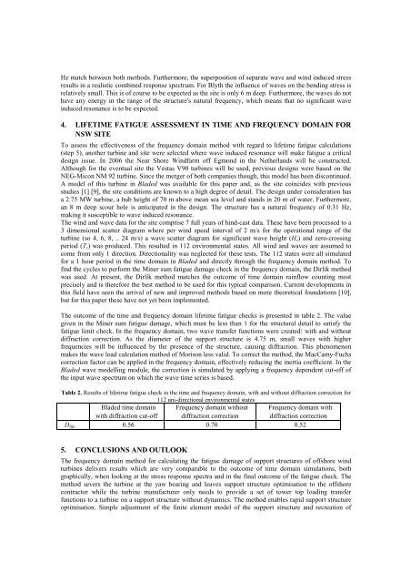
Hz match between both methods. Furthermore, the superposition of separate wave and wind induced stressresults in a realistic combined response spectrum. For Blyth the influence of waves on the bending stress isrelatively small. This is of course to be expected as the site is only 6 m deep. Furthermore, the waves do nothave any energy in the range of the structure's natural frequency, which means that no significant waveinduced resonance is to be expected.4. LIFETIME FATIGUE ASSESSMENT IN TIME AND FREQUENCY DOMAIN FORNSW SITETo assess the effectiveness of the frequency domain method with regard to lifetime fatigue calculations(step 5), another turbine and site were selected where wave induced resonance will make fatigue a criticaldesign issue. In 2006 the Near Shore Windfarm off Egmond in the Netherlands will be constructed.Although for the eventual site the Vestas V90 turbines will be used, previous designs were based on theNEG-Micon NM 92 turbine. Since the merger of both companies though, this model has been discontinued.A model of this turbine in Bladed was available for this paper and, as the site coincides with previousstudies [1] [9], the site conditions are known to a high degree of detail. The design under consideration hasa 2.75 MW turbine, a hub height of 70 m above mean sea level and stands in 20 m of water. Furthermore,an 8 m deep scour hole is anticipated in the design. The structure has a natural frequency of 0.31 Hz,making it susceptible to wave induced resonance.The wind and wave data for the site comprise 7 full years of hind-cast data. These have been processed to a3 dimensional scatter diagram where per wind speed interval of 2 m/s for the operational range of theturbine (so 4, 6, 8, .. 24 m/s) a wave scatter diagram for significant wave height (H s ) and zero-crossingperiod (T z ) was produced. This resulted in 112 environmental states. All wind and waves are assumed tocome from only 1 direction. Directionality was neglected for these tests. The 112 states were all simulatedfor a 1 hour period in the time domain in Bladed and directly through the frequency domain method. Tofind the cycles to perform the Miner sum fatigue damage check in the frequency domain, the Dirlik methodwas used. At present, the Dirlik method matches the outcome of time domain rainflow counting mostprecisely and is therefore the best method to be used for this typical comparison. Current developments inthis field have seen the arrival of new and improved methods based on more theoretical foundations [10],but for this paper these have not yet been implemented.The outcome of the time and frequency domain lifetime fatigue checks is presented in table 2. The valuegiven in the Miner sum fatigue damage, which must be less than 1 for the structural detail to satisfy thefatigue limit check. In the frequency domain, two wave transfer functions were created: with and withoutdiffraction correction. As the diameter of the support structure is 4.75 m, small waves with higherfrequencies will be influenced by the presence of the structure, causing diffraction. This phenomenonmakes the wave load calculation method of Morison less valid. To correct the method, the MacCamy-Fuchscorrection factor can be applied in the frequency domain, effectively reducing the inertia coefficient. In theBladed wave modelling module, the correction is simulated by applying a frequency dependent cut-off ofthe input wave spectrum on which the wave time series is based.Table 2. Results of lifetime fatigue check in the time and frequency domain, with and without diffraction correction for112 uni-directional environmental statesBladed time domainwith diffraction cut-off<strong>Frequency</strong> domain withoutdiffraction correction<strong>Frequency</strong> domain withdiffraction correctionD life 0.56 0.70 0.525. CONCLUSIONS AND OUTLOOKThe frequency domain method for calculating the fatigue damage of support structures of offshore windturbines delivers results which are very comparable to the outcome of time domain simulations, bothgraphically, when looking at the stress response spectra and in the final outcome of the fatigue check. Themethod severs the turbine at the yaw bearing and leaves support structure optimisation to the offshorecontractor while the turbine manufacturer only needs to provide a set of tower top loading transferfunctions to a turbine on a support structure without dynamics. The method enables rapid support structureoptimisation. Simple adjustment of the finite element model of the support structure and recreation of