handbook hood fsw908tc wh/xs 9925084 110.0030 ... - Franke PIM
handbook hood fsw908tc wh/xs 9925084 110.0030 ... - Franke PIM
handbook hood fsw908tc wh/xs 9925084 110.0030 ... - Franke PIM

You also want an ePaper? Increase the reach of your titles
YUMPU automatically turns print PDFs into web optimized ePapers that Google loves.
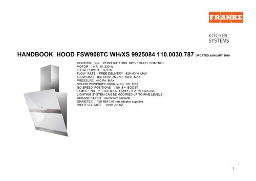
HANDBOOK HOOD FSW908TC WH/XS <strong>9925084</strong> <strong>110.0030</strong>.787 UPDATED JANUARY 2010CONTROL type : PUSH BUTTONS KEY- TOUCH CONTROLMOTOR : NR 01 330 WTOTAL POWER : 370 WFLOW RATE - FREE DELIVERY : 920 M3/H MAXFLOW RATE IEC 61591 850/740 M3/H MAXPRESSURE 440 PA MAXSOUND POWER(IEC 60704-2-13): 66 DBANO SPEED POSITIONS : N0 8 + BOOSTLAMPS : NR 02 HALOGEN LAMPS X 20 W each oneLIGHTING SYSTEM CAN BE MODIFIED UP TO FIVE LEVELS.GREASE FILTER : aluminium cassetteDIAMETER : 150 MM-120 mm adaptor suppliedIMPUT VOLTAGE 230V -50 HZ1
TECHNICAL DATASPEED BOOST 8 7 6 5 4 3 2 1Q MAX 920 750 650 550 480 410 350 280 200Q IEC 850 700 620 530 460 390 330 265 190P 440 420 400 390 360 320 280 200 100W 330 220 180 135 110 90 70 50 35DBA 66 61 58 55 52 49 46 42 352
ELECTRICAL CONNECTION •Connect the <strong>hood</strong> to the mains through a two-pole switch having a contact gap of at least 3mm.• Remove the grease filters (see paragraph Maintenance) being sure that the connector of thefeeding cable is correctly inserted in the socket placed on the side of the fan.Metal grease filtersMetal filters can be washed also in a dish machine. They need to be washed everytime a drop-symbol appears in the display or at least every two months. In case ofvery frequent use these have to be washed even more often. Alarm reset • Pressthe G-key for at least 2 seconds.Cleaning• Open the comfort panel.• Remove the filters one by one by pushing them backwards and pulling themdown contemporaneously.• Wash the filters. Pay attention not to bend them. Make sure that filters arecompletely dry before putting them into their seat. (a possible modification of thefilter surface doesn’t influence its efficiency).• Place the filters again into their seats and make sure that the handle of the filterremains outside.• Close the comfort panel.5
Hood body mountingFirstly, it is necessary to adjust the two Vr-screws of the 11abrackets,at minimun (B).• Hang the <strong>hood</strong> body on the two brackets 11a.• Connect the <strong>hood</strong> to the mains supply by means of a bipolar switchwith at least 3 mm contact gap.• Press the “A”-key for one second (see Part USE) to open the upperpanel.• Remove the metal filters.• In order to align the <strong>hood</strong> it is necessary to adjust the Vr-screwsfrom inside the <strong>hood</strong>.• Fasten the safety screw 11.• Fit again the metal filters into their seats and close the upper panelby pressing “L”-key for one second (see Part USE).• Disconnect the <strong>hood</strong> from the mains supply. Attention: the upperpanel stops if any barrier occurs in its way during the panel openingor closing.To open the panel it is enough to remove the barrier and press thekey once again.6
KEY- FUNCTIONA Upper panel closed: <strong>wh</strong>en pressed forabout one sec-ond it opens the upper panel.It switches the motor on at the latest selectedspeed. Upper panel open: <strong>wh</strong>en shortlypressed it switches the motor on/offB Decreases the suction speed.C Increases the suction speed.D Functioning only <strong>wh</strong>en the upper panel isopen. This speed has been timed at 10minutes. After that time the system activatesautomatically the latest selected speed. Thefunction is suitable for cooking conditions<strong>wh</strong>en vapours and smells are of the utmostemission.E Functioning only <strong>wh</strong>en the upper panel isopen. By pressing this key it is possible to setup the motor to a suction speed at 100 m3/h .F Functioning only <strong>wh</strong>en the motor is on. Bypressing this key it is possible to set theDISPLAYIndicates the selected speed.The number of lit LEDS decreases.The number of lit LEDS increases.I flashes and all the LEDS on the display are lit. By pressing the keythe function is deactived24 appears and the LEDS extinguish one by one. By pressing thekey the function is stoppedA flashing clock-symbol appears.By pressing the key the function is7
delayed shutdown of the motor and thelighting to 30 minutes.G By pressing this key for about 2 seconds itis possible to reset the filter saturation alarmH By pressing this key the intensity of thelighting system can be modified up to fivelevels.I Upper panel closed: <strong>wh</strong>en pressed for about1 second it opens the upper panel and setsthe lights at the maximum intensity. Upperpanel open: <strong>wh</strong>en shortly pressed it switchesthe lights on/off.L Upper panel closed: <strong>wh</strong>en pressed forabout one second it opens the upper paneland switches the motor on at the third speedand the lights at the maximum intensity.Upper panel open: <strong>wh</strong>en pressed for about 1second it switches off motor and lightsresetting every activated function, and closesthe upper panel.stoppedA drop symbol indicates that the metal grease filters saturation alarmhas been activated, and the filters need to be washed. The alarm istriggered after 100 working hours. C indicates that the charcoal filtersatura-tion alarm has been activated, and the filter has to bereplaced. The alarm s triggered after 200 working hours.Keyboard lock: it is possible to jam the keyboard <strong>wh</strong>en, for example, cleaning the glass. Themotor and lights are switched off, and upper panel can be open or closed. By pressing the F-key (Delay) for about 5 seconds the keyboard block can be activated or de-activated. Thisfunction is confirmed by a Beep and by moving motor LEDS on display.8
• Remove the metal grease filters.• Remove the charcoal filter as indicated in the picture.• Place the filter again into its seat.• Place again the metal grease filters into their place.Charcoal filter (recycling version)This filter cannot be washed or regenerated. It must bereplaced <strong>wh</strong>en the C appears on the display or at least onceevery 4 months.The filter saturation alarm has to be activated already before.Activation of the alarm signal • In the recycling version <strong>hood</strong>sthe filter saturation alarm must be activated during theinstallation or later.• Switch off the <strong>hood</strong> and the lights.• Press the E-key for about 5 seconds until the last twosegments of the motor LEDS are lit on the display.• By releasing the E-key the clock icon starts to flash.• Within 3 seconds press the D-key to activate/deactivatecharcoal filter saturation alarm.• C-symbol lit - charcoal filter saturation alarm ACTIVATED. •C-symbol unlit - charcoal filter saturation alarmDEACTIVATED.SUBSTITUTION OF THE CHARCOAL FILTERAlarm reset• Switch off the motor and the lighting system.• Press the G-key for at least 2 seconds. Substitution of the filter• Open the confort panel.LIGHT REPLACEMENT20 W halogen light. • Extract the lamp from the lamp holder by pulling gently. • Replace with another of thesame type, making sure that the two pins are properly inserted in the lamp holder socket holes.9
Replacing the fuseThe <strong>hood</strong> panel opening and closing mechanism is controlled by a starter motor <strong>wh</strong>ich is activated by afuser.This fuser works only on the starter motor. In case the fuser gets damaged <strong>wh</strong>en the panel is closed it isbe necessary to manually unblock the panel. In this case proceed as follows:• Remove the cover placed up on the left side.• Press the releasing lever with the screwdriver as much as necessary to enable the manual opening ofthe panel.• After having completely opened the panel remove the metal grease filters, as explained in the partconcerning the filter cleaning.• The fuser is placed up on the right side. Turn the fuser holder as indicated. Replace the fuser with onehaving the same features.• Put the fuser holder and grease filters into their place again. Make sure that the <strong>hood</strong> functionscorrectly.In case the panel doesn’t work correctly it is necessary to contact an authorized technician. If the fusergets damaged being the panel open, it is sufficient to simply remove the grease filters and replace thefuser .10
PositionSpare partcode<strong>Franke</strong>fun number description quantity Product code Serial numberin1 1961016 133.0036.291 SELF-SUPOORTIN FILTER 3 <strong>9925084</strong>2 1961163 133.0063.884 LOWER PANEL WHITE + FRAME SS 1 <strong>9925084</strong>FSW9083 1961302 133.0052.010 SET HALOGEN LAMP+ SPRING 2 <strong>9925084</strong>4 9925203 112.0016.755 CHARCOLAL FILTERS 2 <strong>9925084</strong>5 1961310 133.0063.885 UPPER PANEL MIRROR/SWING 1 <strong>9925084</strong>WHITE6 1961556 133.0055.984 HINGE FOR PANNEL NO 02 PIECES 1 <strong>9925084</strong>10 1961023 133.0061.271 CARD FILTER NET 1 <strong>9925084</strong>16 1960647 133.0016.965 DIRECT. GRID. D150 BK 1 <strong>9925084</strong>20 1961027 133.0062.486 CONTROL ELECTRONIC BOARD 1 <strong>9925084</strong>23 1961280 133.0046.958 SET TRANSFORMER 40 W 1 <strong>9925084</strong>28 1960080 133.0017.670 FLAT CABLE F. CONTROL (10) 1 <strong>9925084</strong>29 1961414 133.0062.483 WIRING CONNECTION 8 WAYS 1 <strong>9925084</strong>31 1961304 133.0062.488 CONTROLS ELECTRONIC BOARD 1 <strong>9925084</strong>ASSEMBLY32 1961547 133.0062.487 SCREW FOR FIXING VISOR 12 1 <strong>9925084</strong>PIECES35 1961375 133.0016.871 HALOGEN LAMP 12V 20W 2 PIECES 1 <strong>9925084</strong>37 1961033 133.0036.581 MICRO-SWITCHES 2 <strong>9925084</strong>43 1961522 133.0062.489 REDUCTOR MICRO MOTORS 12VCC 1 <strong>9925084</strong>50 1961305 133.0062.490 SET OPENING PANEL1 <strong>9925084</strong>MIRROR/SWING53 1961306 133.0055.947 KIT ELEC.CARD+TERMINAL1 <strong>9925084</strong>BLOCK+COVER57 1961521 133.0052.184 KIT FUSE 5X20T800MA 1 <strong>9925084</strong>102 1961272 133.0056.065 CONTROLS ASSEMBLY 1 <strong>9925084</strong>104 1961053 133.0059.282 FLAT EXTENSION MOTOR 10 WAYS 1 <strong>9925084</strong>105 1960187 133.0016.953 WIRE LOCK 1 <strong>9925084</strong> IH07A106 1960026 133.0016.855 MALE CONNECTION 6 WAYS 1 <strong>9925084</strong> IH07A303 1960020 133.0016.849 CAPACITOR 10MF 1 <strong>9925084</strong> IH09E303 1961530 133.0072.891 CONDENSER 10MF 400V 1 <strong>9925084</strong> IH09F306 1960089 133.0016.896 SX MOTOR SUPPORT 1 <strong>9925084</strong> IH07A307 1960090 133.0016.897 DIFFUSER UPPER CASING 1 <strong>9925084</strong> IH07A308 1960002 133.0016.838 POWER PACK MOTOR 1 <strong>9925084</strong> IH07A309 1960088 133.0016.895 DX MOTOR SUPPORT 1 <strong>9925084</strong> IH07A311 1960028 133.0016.857 FEMALE CONNECTOR 6 WAYS 1 <strong>9925084</strong> IH07ASerial numberout
312 1960014 133.0016.843 ELECTRIC CABLE 1 <strong>9925084</strong>317 1960657 133.0017.169 DIFFUSER FIXING BRACKET 1 <strong>9925084</strong> IH07A330 1961274 133.0051.414 SET CONNECTION FOR MOTOR 1 <strong>9925084</strong>399 1961397 133.0017.045 KIT MOTOR ASSEMBLY PRO 220- 1 <strong>9925084</strong>240V501 1961308 133.0051.697 UPPER CHIMNEY STAINLESS STEEL 1 <strong>9925084</strong>502 1961275 133.0046.952 SET 2 FIXING BRACKETS 1 <strong>9925084</strong> IH08A502 1960566 133.0017.166 UPPER CHIMNEY FIXING BRACKET 1 <strong>9925084</strong> IH07N504 1961276 133.0046.956 SET FLANGE- CONNECTION 1 <strong>9925084</strong>505 1960658 133.0017.095 UPPER CHIMNEY H500MM 1 <strong>9925084</strong> IH07N508 1960200 133.0016.959 SPIGOT 120-150 1 <strong>9925084</strong>509 1960659 133.0017.094 LOWER CHIMNEY X A500 1 <strong>9925084</strong>
I Schema Elettrico NL Schema ElectrischGB Electric Diagram E Esquema EléctricoF Schéma Electrique PT Esquema EléctricoD Schema ElektrischI Schema Elettrico NL Schema ElectrischGB Electric Diagram E Esquema EléctricoF Schéma Electrique PT Esquema EléctricoD Schema Elektrisch436003304 AD1_038 r2 436003304 AD1_038 r2