P3838_3 Mira Fino.pmd - QS Supplies
P3838_3 Mira Fino.pmd - QS Supplies
P3838_3 Mira Fino.pmd - QS Supplies

You also want an ePaper? Increase the reach of your titles
YUMPU automatically turns print PDFs into web optimized ePapers that Google loves.
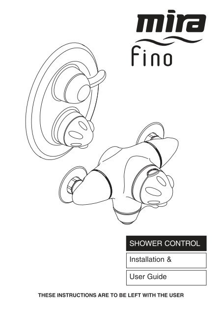
SHOWER CONTROLInstallation &User GuideTHESE INSTRUCTIONS ARE TO BE LEFT WITH THE USER
Contents1 ........ Introduction .......................................................................................... 32 ........ Important Safety Information ............................................................. 33 ........ Pack Contents Checklist..................................................................... 44 ........ Dimensions .......................................................................................... 65 ........ Specification ........................................................................................ 76 ........ Installation Requirements................................................................... 97 ........ Installation ..........................................................................................148 ........ Commissioning ..................................................................................279 ........ Operation .............................................................................................3010 ...... Fault Diagnosis ...................................................................................3211 ...... Maintenance ........................................................................................3412 ...... Spare Parts ..........................................................................................41Guarantee, Customer Care Policy, and How to contact us ......... Back coverIf you experience any difficulty with the installation or operation of your newshower control, then please refer to Section 10, "Fault Diagnosis", beforecontacting Kohler <strong>Mira</strong> Limited. Our telephone and fax numbers can befound on the back cover of this guide.2
Section1 IntroductionThank you for purchasing a quality <strong>Mira</strong> product. To enjoy the full potential of your newproduct, please take time to read this guide thoroughly, having done so, keep it handy forfuture reference.The <strong>Mira</strong> <strong>Fino</strong> is a thermostatic shower control with independent selection of spray forceand temperature. The shower control incorporates a wax capsule temperature sensingunit. This provides an almost immediate response to changes in pressures or temperatureof the incoming water supplies to maintain the selected temperature. An adjustablemaximum temperature stop is provided which limits the temperature to the desired level.An override button allows the user to exceed the preset maximum temperature. The flowcontrol utilizes ceramic plate technology operating directly on the outlet to provideprecise control and isolation of the water outlet. The <strong>Mira</strong> <strong>Fino</strong> also includes checkvalvesand strainers.Shower controls covered by this guide:<strong>Mira</strong> <strong>Fino</strong>An exposed shower control for connection to exposed (rising or falling) or rear entrypipework.<strong>Mira</strong> <strong>Fino</strong> BA built-in shower control for connection to concealed pipework.Section2Warning!Important Safety InformationImportant Safety Information1SectionProducts manufactured by us are safe provided they are installed, used and maintainedin good working order in accordance with our instructions and recommendationsCaution!1. Read all of these instructions.2. Retain this guide for later use.3. Pass on this guide in the event of change of ownership of the installation site.4. Follow all warnings, cautions and instructions contained in this guide.5. The plumbing installation must comply with the requirements of UK Water Regulations/Byelaws (Scotland), Building Regulations or any particular regulations and practices,specified by the local water supplier. The installation should be carried out by aplumber or contractor who is registered or is a member of an association suchas:- Institute of Plumbing (IOP), throughout the UK.- National Association of Plumbing, Heating and Mechanical Services Contractors(NAPH & MSC), England and Wales.- Scottish and Northern Ireland Plumbing Employers’ Federation(SNIPEF), Scotland and Northern Ireland.6. Anyone who may have difficulty understanding or operating the controls of any showershould be attended whilst showering. Particular consideration should be given to theyoung, the elderly, the infirm, or anyone inexperienced in the correct operation of thecontrols.3
Section3 Pack Contents Checklist⌧ Tick the appropriate boxes to familiarise yourself with the part names and to confirmthat the parts are included.1. <strong>Mira</strong> <strong>Fino</strong> Surface Mounted Shower Control1 x <strong>Fino</strong> Shower Control 1 x Quad Key 2 x Compression Nuts 2 x Olives 2 x Pipe Concealing Plates 2 x Fixing Screws 2 x Wallplugs 1 x 3 mm A/F Hexagon Wrench 4
2. <strong>Mira</strong> <strong>Fino</strong> Built-in Shower Control1 x Quad Key 1 x <strong>Fino</strong> Built-in Shower Control (with bracket, cavity seal andbuilding-in shroud fitted)1 x Concealing Plate Assembly 3 x Compression Nuts 3 x Olives 3 x M5 x 60 mm (two fitted) 2 x Fixing Screws 2 x Wallplugs 3. Documentation1 x Installation and User Guide 1 x Customer Support Brochure 2 x M4 x 30 mm 1 x Silicone Sealant 5
Section4Dimensions38 mm110 mm153 mm90 mm209 mm<strong>Mira</strong> <strong>Fino</strong> Shower Control6 mm min/23 mm max.20 mm80 mm 210 mm56 mm 68 mm157 mm<strong>Mira</strong> <strong>Fino</strong> Built-in Shower Control6All dimensions are nominal and in millimetres
5SPECIFICATIONSSpecificationsSectionPressure RangeOptimum maintained pressure: 1 bar (Conversion 1 bar=10 Metres water= 100kPa).Maximum maintained pressure: 5 bar.Maximum static pressure: 10 bar.Maximum flow rate: 40 l/min.Note! For optimum performance, the initial supply pressures should benominally equal.The <strong>Mira</strong> <strong>Fino</strong> will maintain a satisfactory spray pattern and thermostaticperformance with inlet pressures down to 0.2 bar.TemperaturesClose temperature control is provided between 30 and 45 °C.Note! The temperature control specification, outlined below, is achieved withthe blend set between 35 °C and 45 °C, with supply temperatures of 15 °Ccold and 65 °C hot, AND, nominally equal inlet supply pressures.The blended temperature is maintained within 1 °C with a 10 °C change inthe hot or cold supply.The blended water temperature is maintained within 1 °C when the pressurebetween the inlet and outlet is halved (defined as a pressure loss ratio of 2:1)on either the hot or cold side.The shower control will maintain temperature control with a pressure loss ofup to 10:1.The wax capsule sensor effects a shut down to seepage in approximately 2seconds if the cold supply fails. Shut down to seepage is only achieved if thehot supply is 12 °C above the blend temperature.Maximum hot water supply temperature is 85 °C although maximumrecommended is 60 °C for safety reasons.ConnectionsInlet15 mm Compression or 1 /2'' BSP male (<strong>Fino</strong>).15 mm Compression (<strong>Fino</strong> B).Outlet1/2'' BSP male (<strong>Fino</strong>), for connection to bottom outlet flexible hose only.15 mm Compression or 1 /2'' BSP male (<strong>Fino</strong> B).7
StandardsDesigned to comply with BS EN 1111 and 1287 for thermostatic mixing valves,and to be used within systems designed to BS6700.Flow Rates<strong>Fino</strong> with Linesse Fittings High Capacity Spray Plate5040ECO-STARTSTARTSOOTHEFORCEFLOWRATE lpm3020100 0 100 200 300 400 500PRESSURE LOSSkPa<strong>Fino</strong> with Linesse Fittings Low Capacity Spray Plate5040ECO-STARTSTARTSOOTHEFORCEFLOWRATE lpm30201000100 200 300 400 500PRESSURE LOSS kPa8
Section6 Installation Requirements1. Layout and sizing of pipework MUST be such that nominally equal inlet supplypressures are achieved and effects of other draw-offs are minimised.2. The <strong>Mira</strong> <strong>Fino</strong> is suitable for installation as part of a gravity-fed plumbing system.Minimum inlet pressures of 0.2 bar (2 metre head) are required, though inletpressures of 1 bar (10 metre head) are recommended for optimum performance.If minimum inlet pressures are not available then it will be necessary to install apump.3. When used with a high pressure system above 5 bar maintained pressure,a pressure reducing valve will be necessary. It is important that the systempressures are within the range specified for the <strong>Mira</strong> <strong>Fino</strong>.If the system pressure is not known then the system pressure MUST be measured.Pressures are those present at the inlet to the appliance either whilst running(maintained) or in the off state (static). Nearby hot and cold taps connected to thesame proposed feed pipes as the appliance can be used to measure the staticpressure. No other fitting or appliance should be in use at this time.4. Supply pipes MUST be flushed to clear debris before connecting the showercontrol.5. Conveniently situated isolating valves MUST be fitted for servicing purposes.6. If the shower control is to be used with a fully modulating multipoint waterheater, fully modulating combination boiler, thermal store or unvented systeman expansion vessel must be fitted to accommodate the expansion of water inthe domestic hot water supply (this may already be part of the system, checkthe details on the boiler/heater or contact the boiler/heater manufacturer).7. No form of outlet flow control should be fitted, only <strong>Mira</strong> recommended fittingsshould be used in the outlet pipework.Typical Suitable InstallationsKey to symbols appearing throughout this guide.Float operated valveStop or servicing valveShower controlWarning or overflow pipeTwin impeller inlet pumpTempering valveMini expansion vesselNon-return ValveDrop tight pressure reducingvalve (PRV)9
Instantaneous gas-heated showers (e.g. combination boilers)The shower control MUST be installed with a multipoint gas water heater or combinationboiler of a fully modulating design (i.e. where the water draw-off rate indirectly controlsthe gas flow rate to the burner).A drop tight pressure reducing valve MUST be fitted if the supply pressures exceed 5 barmaintained.An expansion vessel MUST be fitted (and regularly maintained) as shown in the diagrambelow to ensure that excess pressures do not damage the product. This may already befitted within the boiler (check with the manufacturer) and is in addition to the normallylarger central heating expansion vessel.The hot supply temperature MUST be at least 12 °C hotter than the required blendtemperature for optimum performance.COLDHOT10
Gravity fed showers - The shower control MUST be fed from a cold water storagecistern and hot water cylinder providing nominally equal pressures.Mains pressurised instantaneous hot water shower, heated from a thermal storePackages of this type, fitted with a tempering valve can be used.A drop tight pressure reducing valve MUST be fitted if the supply pressures exceed 5 barmaintained.An expansion vessel MUST be fitted (and regularly maintained) if any form of backflowprevention device is fitted, e.g. non-return valve, PRV. This will ensure that excessexpansion or pulse pressures do not damage the product or the plumbing system. Theexpansion vessel may already be fitted externally or internally within the thermal store(check with thermal store manufacturer).COLDHOT11
Unvented mains pressure showersThe shower can be installed with an unvented, stored hot water cylinder. Only a"competent person" as defined by the Building Regulations may fit this type of system.For packages with no cold water take off after the appliance reducing valve, it will benecessary to fit an additional drop tight pressure reducing valve when the mains pressureis over 5 bar. The drop tight pressure reducing valve must be set at the same value as theunvented package pressure reducing valve.Note! An expansion vessel MUST be fitted (and regularly maintained) if any form ofbackflow prevention device is fitted, e.g. non-return valve, PRV. This will ensure thatexcess expansion or pulse pressures do not damage the product or the plumbing system.Safety devicesnot shownfor clarityCOLDHOTExpansionVesselHighInletPressureReducedpressure tocold inlet ofshowerHighInletPressureReducedpressure tocold inlet ofshowerReducedpressure tounventedcylinderCombined outlet PRVwith internal non-return valves- Expansion vessel required.Reducedpressure tounventedcylinderCold takeoff after PRV- Expansion pressure taken up byunvented cylinder expansion vessel.12
Pumped showers (inlet pumps)The shower can be installed with an inlet pump (twin impeller). The pump MUST belocated on the floor next to the hot water cylinder. The hot water cylinder/vent pipes mustbe arranged as shown to achieve air separation.90 °30 to 60 °Air Separation13
Section71. Before you complete the installation,determine whether the hot or cold waterservices will be connected to the showercontrol from the bottom (rising) or from thetop (falling).Before you decide on the final position ofyour shower control, please bear in mindthe following:Decide on a suitable position for the showercontrol. The position of the shower controland the shower fittings must provide aminimum gap of 25 mm between the spilloverlevel of the shower tray/bath and thehandset. This is to prevent backsiphonage.Installation<strong>Mira</strong> <strong>Fino</strong> Surface Mounted Shower ControlRising or Falling Inlet <strong>Supplies</strong>Note! The <strong>Mira</strong> <strong>Fino</strong> is supplied with inletconnections hot left, cold right and bottomoutlet as standard. For installations withreversed hot and cold supplies refer to thesection Installation: "Reversed InletConnection".Falling <strong>Supplies</strong>Hose RetainingRingBackplateSpill-over LevelRising <strong>Supplies</strong>GrubScrew25 mmMinimum2. Remove the backplate by releasing,anticlockwise, the two recessed grub screwswhich retain the backplate against the brassshower control body, using the 3 mm A/Fhexagon wrench (supplied).3. Use the installation template to mark thepositions of the fixing holes for the backplateon the wall.Ensure the holes are vertically aligned.Warning! Ensure there are no buried cablesor pipes in the wall before drilling.4. Drill the two marked fixing holes and fit thewallplugs provided. Secure the backplateto the wall with the two fixing screwsprovided.GrubScrewWallplugsBackplate14Note! Screws with larger heads will foul theshower control body.Fixing Screws
5. Install the inlet pipework.If necessary, use the installation templateto ensure the pipework is in the correctposition.Grub ScrewInletConnectorNippleSpot FacesBackplateGrubScrewO SealInletElbowGrubScrew6. Thoroughly flush the incoming hot andcold water supplies before connectingthe shower control.7. Use the 3 mm A/F hexagonal wrench toloosen the two grub screws that hold theinlet elbows in position.8. Rotate the inlet elbows so that the inletconnector nipple is pointing up for fallingsupplies, or down for rising supplies.Tighten the grub screws.Make sure the elbow is aligned so thatthe grub screws locate into the spotfaces in the inlet elbow.9. Fit the shower control body onto thebackplate and secure by in position withthe two grub screws, using the 3 mm A/Fhexagonal wrench.10. Slide the compression nut, then the olive,over the hot and cold inlet pipework. Ifnecessary, smear ‘liquid jointing’ sparinglyon the pipe end and the outside of the olive.Inlet PipeworkCompressionNutOlive11. Insert the hot and cold inlet pipework into theopening of the inlet connector nipple thenslide the olive and compression nut intoplace.12. Carefully tighten the compression nut. Usea cloth to protect the plated surfaces.InletConnectorNippleShower Control15
Back Inlet <strong>Supplies</strong>1. Follow the shower control installationprocedure as for “Rising or FallingInlet <strong>Supplies</strong>”: instructions 1. to 4.inclusive.Spirit Level2. Use the cardboard installation templateto mark the positions of the holes forthe backplate and the pipe centres.3. Remove the plaster and brickwork tothe required depth to conceal the supplypipework.Note! Depth must be sufficient toprevent pipe concealing plates foulingon the plumbing elbows.Installation Template4. Install the hot and cold water supplypipework ensuring that the pipe endsemerge from the wall surface at 153mm centres, and project from thefinished wall surface by 13 mm.Use the installation template to ensurethe pipes are in the right position.153 mm32 mmConcealingPlate13 mm fromfinished wallsurfaceBackplateCircularRecessElbow10 mm minbetween elbowand finishedwall surface16
Backplate5. Make good the wall surface, allowing fortwo circular recesses measuring 32 mmdiameter x 10 mm depth, to accept thetwo pipework concealing plates.Fit the pipework concealing plates overhot and cold water supply pipework.6. Thoroughly flush the incoming hot andcold water supply pipes beforeconnecting the shower control. Failureto do so may result in productmalfunction.7. Slip the compression nuts and olivesover the supply pipes.Compression Nut8. Locate the shower control body onto thebackplate and inlet supply pipework,then secure by tightening, clockwise,the two recessed grub screws, using the3 mm A/F hexagon wrench (supplied).Tighten the compression nuts, using ifnecessary, a cloth to protect the platedsurfaces.Turn on the water supplies and checkfor any leaks!9. This completes the installation of the<strong>Mira</strong> <strong>Fino</strong> for “Back Inlet <strong>Supplies</strong>”.17
<strong>Mira</strong> <strong>Fino</strong> Built-in Shower ControlSolid, Dry Lined, Stud Partition or Dry Partition Wall StructuresThe built-in shower control incorporates an integral wall mounting bracket assembly whichcan be used to install the shower into a solid, dry-lined, stud partition or dry partition wallstructure, shower cubicle or laminated panel.1. Before you decide on the final position ofyour shower control, please bear in mindthe following:- Decide on a suitable position for theshower control. The position of theshower control and the showerfittings must provide a minimum gapof 25 mm between the spill-overlevel of the shower tray/bath and thehandset. This is to preventbacksiphonage.- Determine whether the hot or coldwater services will be connected to theshower control from the top (falling) orfrom the bottom (rising).2. Familiarise yourself with the hot and coldwater inlet ports and outlet port. They canbe identified as follows:The <strong>Mira</strong> <strong>Fino</strong> is supplied with inletconnections hot left, cold right and topoutlet as standard.To change the position of the inlet refer to“Reversed Inlet Connection”:instructions 1. to 6. inclusive.3. Determine the route for the incoming hotand cold water supply pipework. The outletpipework to a flexible shower fitting is bestpositioned to emerge above and to one sideof the shower control to allow the flexiblehose to drape around the underside of theshower preventing the hose from interferingwith the knob (refer to diagram).Hose RetainingRingSpill-over Level25 mmMinimum18
180 mm125 mm4. If installing the shower into a solid wall,mark an opening sufficient to accommodatethe shower control approximately 180 mmx 125 mm on the surface of the wall.Alternatively, if installing the shower into adry-lined wall, use the installation templateand mark around the outside edge.5. Mark the route of the supply and outletpipes.Spirit LevelInstallation TemplateFinished wallsurface6 mm Minimum DepthSupportBracket6. Remove the plaster and brick/block for theshower control to a depth of between 64mm and 81 mm from the finished surfaceof the wall. The support bracket requires aclearance depth of 58 mm, with a finishedwall surface thickness of between 6 and 23mm.Note! The maximum and minimum depthlevels are indicated on the outer sectionsof the building-in shroud.7. Remove the plaster and brick/block workfor the supply and outlet pipes.Finished wallsurface23 mmMaximumDepth58 mm19
8. Mark the final position on the wall of thetwo larger outer diameter fixing holes inthe flanges of the wall mounting bracket.This bracket must be fixed at 45°.9. Drill and suitably plug the two markedfixing holes.Position the hot and cold supplies.10. Install the shower control aligning the twoflange holes of the wall mounting bracketassembly with the pre-drilled fixing holes.Secure the shower control with the twofixing screws supplied.11. Remove all three sections of the buildinginshroud. Align the hot and cold supplyand top outlet pipes with the valve but donot connect to the valve.12. Remove the support bracketand valve unit from the wall andthoroughly flush the hot and cold watersupply pipes. The supplies must be cleanand free from debris before connectingthe shower control. Failure to doso may result in product malfunction.Note! The <strong>Fino</strong> is supplied with inletconnections hot left, cold right and topoutlet as standard. For installations withreversed hot and cold refer to Section 9,Reversed inlet connections.20
Compression NutOlive13. Stretch the rubber seal over the valve inletand outlet threads and loosely attach thecompression nuts and olives.ThreadsRubberSeal14. Fix the support bracket and valve unit intothe wall with the two fixing screws.15. Insert the hot and cold supply and top outletpipes through the compression nuts andolives. Ensure that each pipe is pushedfully into the valve.Note! For falling inlet supplies the outletpipe may have to be set deeper into thewall.16. Hold each pipe in position and use a suitablespanner to tighten the compression nuts.Do not pinch the rubber seal.RubberSealCompression Nut17. Using a suitable tool, push the rubber cavityseal over each of the compression nutsand on to the pipework. Do not pierce therubber seal.18. Turn on the water supplies and check forany leaks.21
19 Refit the three building-in shroud sectionsthat you removed earlier. Secure the shroudin position with the screws.FINISH20. Plaster and tile up to the tapered sides ofthe plastic building-in shroud and, whenset, remove the shroud. The two longershroud retaining screws should be kept foruse later.MAXMINMake sure that the finished tiled wall surfaceis within the FINISH arrow on the buildinginshroud.21. Apply a bead of silicone sealant betweenthe rubber seal and the tiled surface.Building-in ShroudSilicone SealantFinished SurfaceRubberSealRubber Cavity Seal22. Fit the back plate over the valve makingsure that the rubber seal is between theplate and the tiled surface. Secure the backplate in position with the three M5 x 60 mmfixing screws (supplied).Back PlateCaution! Make sure that you do notovertighten the screws.22
Flow lever23. Remove the temperature knob from theconcealing plate.Line up the flow lever with the top hub. To fitthe concealing plate, firstly clip it over the topof the back plate and then push it firmly untilit locates on the bottom.Align the temperature knob with the bottomhub and re-attach.24. This completes the installation of the <strong>Mira</strong><strong>Fino</strong> for installation into “Solid, Dry-lined,Stud Partition or Dry Partition WallStructures”.23
Laminated Panel and Shower Enclosures (Front Face)The built-in shower control is supplied with a support bracket that can be used to install the showercontrol into the front face of a stud partition wall structure or shower enclosures. The front faceinstallation of the support bracket is only practical where an applied surface finish e.g. plaster or tilescan conceal flanges of the bracket.Spirit LevelInstallation Template6 mm Minimum DepthFinishedWall SurfaceFinishedWall Surface23 mmMaximumDepth6 mm Maximum Depth58 mmClearanceGreaterthan 6 mmBend tabs outwardsand place spirit level ontabs to level thetemplate1. Follow the shower control installationprocedure as for “Solid, Dry-lined, StudPartition or Dry Partition WallStructures”: instructions 1. to 3.inclusive.2. Use the installation template (supplied)to mark the size of the hole required onthe panel.Bend the tabs outwards and use a spiritlevel to ensure that the hole is markedsymmetrically.Mark around the outside edge of thetemplate.3. Carefully cut the hole in the panel.4. Follow the shower control installationprocedure as for “Solid, Dry-lined, StudPartition or Dry Partition WallStructures”: instructions 8. and 9.inclusive.5. Fix the mounting bracket and valve unit tothe panel with the two fixing screws(alternative fixing screws may berequired). Make sure that the lip on therubber seal is on the outside face of thepanel.6. To complete the installation, followinstructions 11 to 23 of “Solid, Dry-lined,Stud Partition or Dry Partition WallStructures”.24
Laminated Panels and Shower Enclosures (Rear Face)The built-in shower control incorporates an integral wall mounting bracket assemblywhich can be used to install the shower into the rear face of a shower enclosure orlaminated panel.The building-in depth for the integral wall mounting bracket assembly is 58 mm. Theintegral wall mounting bracket assembly can be used to install the shower control into alaminated panel or shower enclosure of between 4 and 21 mm. The building-in depthcalculation must include the final thickness of plaster and tiles.1. Follow the shower control installationprocedure as for “Solid, Dry-lined, StudPartition or Dry Partition WallStructures”: instructions 1. to 3.inclusive.Spirit Level2. Use the installation template (supplied)to mark the size of the hole required onthe panel.Bend the tabs outwards and use a spiritlevel to ensure that the hole is markedsymmetrically.Mark through the inner slots of thetemplate and mark the position of thefixing holes for the support bracket.3. Carefully cut the hole in the panel.4. Drill a 6.0 mm diameter hole at each ofthe marked positions.5. Position the hot and cold supply pipesbut do not connect to valve.6. Remove the three building-in shroudsections and fix the support bracket andvalve unit in position using the two screws(supplied).Pull the cavity wall seal through the hole.7. Align the hot and cold supply and topoutlet pipes with the valve but do notsecure the pipes.Installation TemplateBend tabs outwardsand place spirit levelon tabs to level thetemplate4 mm Minimum Depth21 mmMaximumDepth58 mmClearance8. To complete the installation, followinstructions 12 to 23 of “Solid, Drylined,Stud Partition or Dry PartitionWall Structures”.25
Reversed Inlet Connection<strong>Mira</strong> <strong>Fino</strong> shower controls are supplied with inlet connections hot left, cold right andbottom outlet. The <strong>Fino</strong> Built-in is supplied with inlet connections hot left, cold right andtop outlet as standard.The flow divertors on the exposed and built-in models are colour coded RED and BLUE.To reverse the inlet position proceed as follows:<strong>Fino</strong> Exposed1. Using the 3 mm hexagonal wrench(supplied) remove the grub screws thathold the elbows in position.2. Remove the elbows.3. Remove the coloured flow divertors.4. Refit the flow divertors in the oppositesides (refit the BLUE divertor whereyou removed the RED divertor fromand vice versa).5. Refit the elbows and secure in positionwith the grub screws.6. This completes the procedure for“Reversed Inlet Connection”.ElbowFlow Divertor<strong>Fino</strong> Built-in1. If fitted, carefully prise off the concealingplate assembly using the screwdriverslot at the bottom of the concealingplate.2. Remove the coloured flow divertors,using the supplied quad key.4. Refit the flow divertors in the oppositesides (refit the BLUE divertor whereyou removed the RED divertor fromand vice versa).FiltersFlow Divertors5. To refit the concealing plate assembly,follow instruction 23 of “Solid, Drylined,Stud Partition or Dry PartitionWall Structures”.6. This completes the procedure.for“Reversed Inlet Connection”.Concealing PlateAssembly26
Section8 Commissioning1. Maximum Temperature SettingAll <strong>Mira</strong> <strong>Fino</strong> shower controls are fully performance tested and the maximum temperaturehas been set under ideal installation conditions at the factory. The temperature stop is setto 41 ° C and depressing the override will increase the temperature by 5 ° C toapproximately 46 ° C. Site conditions and personal preference may make it necessary toreset these temperatures.Note! An adequate supply of hot water at least 12 °C above the required temperaturemust be available for correct operation of the shower control.Warning! Altering the position of thetemperature stop will reset the maximumtemperature obtainable with the overrideoperated.1.1. Turn the temperature knob to themaximum temperature stop. Do notdepress the override button.1.2. Turn the flow knob fully anticlockwise(maximum flow) and allow thetemperature to stabilize.1.3. Measure the water temperature. Ifthe temperature is satisfactory thenno adjustment is needed. Ifadjustment is necessary continuewith the commissioning procedure.Temperature HubSecuring Screw1.4. Carefully pull off the temperatureknob.1.5. Remove the temperature hubsecuring screw.Temperature Hub1.6. Use a screwdriver to carefully leveroff the temperature hub. Ensure thatthe pressure washer remains inposition.27
AnticlockwiseIncreaseTemperatureClockwiseDecreaseTemperature1.7. Rotate the temperature spindle untilthe required temperature is obtained.Turn the spindle anticlockwise toincrease the temperature orclockwise to decrease thetemperature.If resistance is felt DO NOT USEFORCE to rotate the spindle as thisis the maximum obtainabletemperature from the shower controlwith the available hot water supplytemperature. FORCE will DAMAGEthe internal components of thecartridge assembly.1.8. Turn the flow knob off (fullyclockwise).1.9. Refit the temperature hub makingsure that the arrow on the hub alignswith the cut out.1.10. Refit the securing screw and thetemperature knob. Check that thetemperature knob can be rotatedfully in both directions.Temperature HubSecuring Screw1.11. Turn the flow knob fully anticlockwise(maximum flow) and check thetemperature is correct and theoverride functions correctly. Ifnecessary repeat the procedure untilthe correct temperature is achieved.Temperature HubTemperature Knob28
Temperature Override Button DisableThe <strong>Mira</strong> <strong>Fino</strong> incorporates a temperature override button that allows the user to overridethe preset maximum temperature. The following procedure can be used to disable theoverride button, limiting the maximum temperature available to the preset value. Thissetting is recommended for the young, the elderly, the infirm, or anyone inexperienced inthe correct operation of the controls.1. Ensure the shower control is turned off.2. Remove the temperature knob.3. Disable the temperature override button as follows;<strong>Fino</strong> B - on the rear of the temperature knob move the lever in the slot, this will eitherlock or release the button depending on how it had been previously set.<strong>Fino</strong> - on the rear of the temperature knob move the small plastic lever to lock it in theindent. Placing the lever in the indent will lock the override button.4. Install the temperature knob back on the valve.<strong>Fino</strong> BTemperatureOverride ButtonTemperatureOverride ButtonMove clockwiseto lockMove anticlockwisetounlockTemperatureOverride ButtonTemperatureOverride Button<strong>Fino</strong>Move the leverinto the indent willlock the overridebutton.Move the leverout of the indentwill unlock theoverride button.29
Section1. <strong>Fino</strong> and <strong>Fino</strong> BThe <strong>Mira</strong> <strong>Fino</strong> incorporates a temperature override button that allows the user tooverride the preset maximum temperature. It is recommended that this facility isdisabled for the young, the elderly and the infirm, or anyone inexperienced in thecorrect operation of the controls. Refer to Section 8, Commissioning: "2.Temperature override button disable".<strong>Fino</strong>9 Operation1.1. Turn the flow lever until thedesired force of water is obtained.Note! When the <strong>Fino</strong> is installedwith a fully modulating multipoint orcombination type gas water heater,the maintained mains waterpressure, and hence the flow, mustbe sufficient to keep the heaterignited. Therefore, it is important toensure that the flow knob is fullyopen to prevent variation in the hotwater supply temperature.1.2. Turn the temperature (outer) knobanticlockwise for warmer water orclockwise for cooler water. Thepreset maximum temperature canbe adjusted as required to suitboth site conditions and the user'scomfort. Refer to Section 8,Commissioning: "1. Maximumtemperature setting".Flow LeverWarning! Operation of the overridebutton will allow a shower temperatureabove the preset maximum.1.3. To override the preset maximumtemperature depress the overridebutton and turn the temperatureknob fully anticlockwise.30Temperature Knob
<strong>Fino</strong> B1.1. Turn the flow lever anticlockwiseuntil the desired force of water isobtained.Note! When the <strong>Fino</strong> is installedwith a fully modulating multipoint orcombination type gas water heater,the maintained mains waterpressure, and hence the flow, mustbe sufficient to keep the heaterignited. Therefore, it is important toensure that the flow knob is fullyopen to prevent variation in the hotwater supply temperature.Flow Lever1.2. Turn the temperature knobanticlockwise for warmer water orclockwise for cooler water. Thepreset maximum temperature canbe adjusted as required to suitboth site conditions and the user'scomfort. Refer to Section 8,Commissioning: "1. Maximumtemperature setting".Warning! Operation of the overridebutton will allow a shower temperatureabove the preset maximum.1.3. To override the preset maximumtemperature depress the overridebutton and turn the temperatureknob fully anticlockwise.Temperature Knob31
Section10 Fault DiagnosisSymptom1. Only hot orcold waterfrom outlet.2. Fluctuatingor reducedflow rate.3. No flowfrom showercontroloutlet.Cause/Rectificationa. Inlet supplies reversed (see reversed inlets section).Check.b. No hot water reaching shower control. Check.c. Check strainers and inlet fittings for blockage.d. Refer to symptom 5 below.e. Installation conditions continuously outside operatingparameters: refer to SPECIFICATION, and 2e below.Normal function of thermostatic control when operatingconditions are unsatisfactory;a. Check strainers and inlet/outlet fittings for flow restriction.b. Make sure that minimum flow rate is sufficient for supplyconditions.c. Make sure that maintained inlet pressures are nominallybalanced and sufficient.d. Make sure that inlet temperature differentials are sufficient.e. (Subsequent to rectification of supply conditions) Checkthermostatic performance; renew thermostatic cartridge, ifnecessary.a. Check strainers and inlet/outlet fittings for blockage.b. Hot or cold supply failure; thermostat holding correctshutdown function: rectify, and refer to symptom 2.eabove.c. Flow control cartridge faulty. Check and renew if necessary.d. Check shower head is not blocked. Clean if necessary.4. Blendtemperaturedrift.5. Hot water incold supplyor viceversa.Indicates operating conditions changed.a. Refer to symptom 2 above.b. Hot supply temperature fluctuation.c. Supply pressure fluctuation.Indicates checkvalves require maintenance, refer toMAINTENANCE.32
Symptom6. Maximumblendtemperaturesetting toohot or toocool.7. Waterleaking fromshowercontrol body.Cause/Rectificationa. Indicates incorrect maximum temperature setting; referto COMMISSIONING.b. As symptom 4 above.c. As symptom 5 above.Seal(s) worn or damaged.a. Obtain service pack and renew all seals.b. (If leak persists from around temperature spindle) Renewthermostatic cartridge.8. Flow knob ortemperatureknob stiff tooperate.9. Drip fromhandsetspray plateassembly orbir sprayplate.10.<strong>Fino</strong> noisyduringoperation.a. Impaired free movement of internal components. Renewthe appropriate cartridge.b. Supply pressures too high. Fit pressure reducing valve.Refer to SPECIFICATIONS for acceptable operatingpressures.c. Pressure build up. This may be due to domestic hot waterexpansion. Fit domestic hot water expansion vessel(available from your local stockist). If one already fitted, itmay be deflated and require repressurization.a. A small amount of water may be retained in the showerfitting after the shower control has been turned off. This isquite normal and should drain after a few minutes.Changing the angle of the shower fitting may vary thedraining time.b. The ceramic plates within the shower control may bedefective. Renew the cartridge assembly. Check that thepressures are not in excess of the maximum for product(refer to sympton 8 above).a. The inlet supply pressures may be unbalanced. Fit a droptight PRV just after the incoming mains stopcock,effectively balancing the hot and cold supply pressures.Ideally set the PRV to 3.5 bar.b. The inlet supply pressures may be high. The maximummaintained pressure should not exceed 5 bar. If greater, fita drop tight PRV installed as detailed above.33
Section11 Maintenance<strong>Mira</strong> products are precision engineered to provide satisfactory performance provided theyare installed and operated in accordance with the recommendations contained in thisguide.The shower control is designed for the minimum of maintenance in normal domestic use.If a malfunction occurs then this will probably necessitate a complete cartridgereplacement.Important! The cartridge contains no internally serviceable parts.When installed in very hard water areas (above 200 p.p.m. temporary hardness) yourinstaller may advise the installation of a water treatment device to reduce the effects oflimescale formation in the heating appliance and spray plates.CleaningMany household cleaners contain abrasives and chemical substances and should not beused for cleaning plated or plastic fittings. These finishes should be cleaned using a mildwashing up detergent or soap solution, and then wiped dry using a soft cloth.The light golden colour finish is softer than the chrome finish and its abrasive resistancemuch less. When cleaning or using tools during maintenance extra care must be taken.Cartridge Renewal (Temperature)Should the cartridge require renewal then the following procedure should be followed:Important! Use only silicone based lubricants when reassembling.<strong>Fino</strong> Exposed (Refer to Figure 1)1. Turn off the water supplies and open the shower control to relieve the trapped waterpressure.2. Carefully pull off the temperature knob.3. Unscrew the headnut and pull out the cartridge.4. Remove the 'C' washer and the headnut from the cartridge.Important! When fitting a new cartridge make sure that you fit the correct hub.5. Carefully fit the new cartridge into the valve body, making sure that it locates correctlyin the slots in the valve body.6. Fit the headnut and secure in position with the 'C' washer.7. The maximum temperature will now require resetting following the procedure “MaximumTemperature Setting” in the section Commissioning.8. Refit the temperature knob.34
'C' WasherWave WasherHubTemperature KnobHeadnutScrewTemperatureCartridge<strong>Fino</strong> Built-in (Refer to Figure 2)Temperature Cartridge Renewal - <strong>Fino</strong>Figure 11. Turn off the water supplies and open the shower control to relieve the trapped waterpressure.2. Using the screwdriver slot at the bottom of the concealing plate, carefully prise off theconcealing plate assembly.3. Unscrew the headnut and pull out the cartridge.4. Remove the 'C' washer and the headnut.Important! When fitting a new cartridge make sure that you fit the correct hub.5. Carefully fit the new cartridge into the valve body, making sure that it locates correctlyin the slots in the valve body.6. Fit the headnut and secure in position with the 'C' washer.7. The maximum temperature will now require resetting following the procedure “MaximumTemperature Setting” in the section Commissioning.8. Refit the concealing plate assembly.35
'C' WasherWave WasherHubHeadnutScrewConcealing PlateAssemblyTemperatureCartridgeTemperature Cartridge Renewal - <strong>Fino</strong> BFigure 236
Checkvalve/Strainer RenewalShould the checkvalve/strainers require renewal or cleaning then the followingprocedure should be followed:Important! Use only silicone based lubricants when reassembling.<strong>Fino</strong> Exposed (Refer to Figure 3)1. Turn off the water supplies and open the shower control to relieve the trapped waterpressure.2. Remove the valve from the backplate by releasing, anticlockwise, the two recessedgrubscrews, using the 3 mm A/F hexagon wrench (supplied).3. Unscrew the compression nuts and carefully release the valve from the wall.4. Remove the grubscrew and remove the elbow.5. Pull out the checkvalve housing and strainer from the elbow.Note! If necessary, clean the checkvalve and the strainer. The checkvalves andstrainers may be cleaned under a jet of water, or renewed. Also ensure that there is nodebris/damage to the 'O' seals6. Fit the strainer to the checkvalve housing.7. Fit the checkvalve assembly into the elbow.8. Fit the elbow into the valve body and tighten the grubscrew.9. Locate the shower control body onto the backplate and inlet supply pipework, thensecure by tightening, clockwise, the two recessed grub screws, using the 3 mm A/Fhexagon wrench (supplied).Tighten the compression nuts, using if necessary, a cloth to protect the plated surfaces.Ensure there are no leaks.CompressionNutGrubscrewCheckvalveHousingElbowStrainerSealCheckvalveCheckvalve/Strainer Renewal - <strong>Fino</strong>Figure 337
<strong>Fino</strong> Built-in (Refer to Figure 4)1. Turn off the water supplies and open the shower control to relieve the trapped waterpressure.2. Using the screwdriver slot at the bottom of the concealing plate, carefully prise off theconcealing plate assembly.3. Using a 12 mm A/F hexagonal wrench or the quad key, unscrew and remove thecheckvalve housing.Note! The strainer will be attached to the checkvalve housing.4. Remove the strainer.Note! If necessary, clean the checkvalve and the strainer. The checkvalves and strainersmay be cleaned under a jet of water, or renewed.5. Fit the strainer onto the checkvalve housing using the clip feature to keep it in place.6. Fit the checkvalve into the valve body and tighten.7. To complete the installation, follow instruction 23 of “Solid, Dry-lined, Stud Partitionor Dry Partition Wall Structures”.CheckvalveStrainerCheckvalveHousing38Checkvalve/Strainer Renewal - <strong>Fino</strong> BFigure 4Concealing Plate Assembly
Flow Cartridge RenewalShould the flow cartridge require renewal or cleaning then the following procedureshould be followed:Important! Use only silicone based lubricants when reassembling.<strong>Fino</strong> Exposed (Refer to Figure 5)1. Turn off the water supplies and open the shower control to relieve the trapped waterpressure.2. Remove the hose from the lever retainer.3. Unscrew and remove the lever retainer using a 12 mm A/F hexagonal key or the quadkey. Remove the flow control lever and the wave washer.4. Undo the flow cartridge retaining nut using a 30 mm A/F spanner and pull out the flowcartridge.Note! Before installing a new flow cartridge make sure that the 'O' seals are correctlyinstalled.5. Fit the new flow cartridge into the valve body.6. Fit the wave washer, the flow control lever and secure in place with the lever retainer.7. Fit the hose to the lever retainer.Valve Body'O' SealFlow CartridgeRetaining Nut'O' SealWave WasherFlow Control LeverFlow Cartridge Renewal - <strong>Fino</strong>Figure 5Lever Retainer39
Important! Use only silicone based lubricants when reassembling.<strong>Fino</strong> Built-in (Refer to Figure 6)1. Turn off the water supplies and open the shower control to relieve the trapped waterpressure.2. Using the screwdriver slot at the bottom of the concealing plate, carefully prise off theconcealing plate assembly.3. Remove the hub retaining screw and remove the hub.4. Unscrew and remove the flow cartridge using a suitable spanner or socket.Note! Before installing a new flow cartridge make sure that the 'O' seals are correctlyinstalled.5. Fit the new flow cartridge into the valve body.6. Fit the hub and secure in position with the hub retaining screw.7. To complete the installation, follow instruction 23 of “Solid, Dry-lined, Stud Partitionor Dry Partition Wall Structures”.Flow CartridgeHubHub Retaining ScrewConcealing Plate Assembly40Flow Cartridge Renewal - <strong>Fino</strong> BFigure 6
Section12Spare Parts<strong>Mira</strong> <strong>Fino</strong> Spare Parts List451.01 Seal Pack - components identified 'A'451.02 Strainer Pack451.03 Thermostatic Cartridge451.04 Flow Cartridge Assembly451.05 Check Valve Assembly451.06 Inlet Connection Pack - chrome451.07 Inlet Connection Pack - light gold451.08 Inlet Elbow - chrome451.09 Inlet Elbow - light gold451.10 Body - chrome451.11 Body - light golden451.12 Temperature Knob - chrome451.13 Temperature Knob - light golden451.14 Flow Lever - chrome451.15 Flow Lever - light golden451.16 Backplate451.17 Headnut451.18 Component Pack - components identified 'B'451.19 Screw Pack - components identified 'C'451.24 Hub Pack451.86 Installation Template41
<strong>Mira</strong> <strong>Fino</strong> Spare Parts Diagram451.03451.12451.13BA451.17451.24B451.86BACB451.16BCC451.03AA451.06451.07451.02451.05451.10451.11451.04451.08451.09451.14451.1542
<strong>Mira</strong> <strong>Fino</strong> B Spare Parts List451.01 Seal Pack - components identified 'A'451.02 Strainer Pack451.03 Thermostatic Cartridge451.22 Check Valve Assemblies451.23 Flow Cartridge451.24 Hub Pack451.34 Cavity Wall Seal451.35 Concealing Plate Assembly - chrome451.36 Concealing Plate Assembly - satin chrome451.37 Concealing Plate Assembly - light gold451.43 Support Bracket451.44 Screw Pack - components identified 'B'451.45 Building-in Shroud451.46 Body and Support Bracket43
<strong>Mira</strong> <strong>Fino</strong> B Spare Parts DiagramB451.43451.34B451.46451.23A451.02451.03A451.22A451.24451.45B451.35451.36451.3744
Notes45
46Notes
Notes47
SectionGuarantee of Quality<strong>Mira</strong> Showers guarantee products against any defect ofmaterials or workmanship for one year from the date ofpurchase (5 years for the NEW <strong>Mira</strong> Excel/<strong>Fino</strong> (valve only)).To validate the guarantee, please return your completedregistration card.Within the guarantee period we will resolve defects, free ofcharge, by repairing or replacing parts or modules as we maychoose.To be free of charge, service work must only be undertakenby <strong>Mira</strong> Showers or our approved agents in Northern Irelandand Republic of Ireland.Service under this guarantee does not affect the expirydate. The guarantee on any exchanged parts or productends when the normal product guarantee period expires.Not covered by this guarantee:Damage or defects arising from incorrect installation, improperuse or lack of maintenance, including build-up of limescale.Damage or defects if the product is taken apart, repaired ormodified by any person not authorised by <strong>Mira</strong> Showers or ourapproved agents.This guarantee is in addition to your statutory and otherlegal rights.Before using your showerPlease take the time to read and understand the operatingand safety instructions detailed in this manual.What to do if something goes wrongIf when you first use your shower it doesn’t function correctly,first contact your installer to check that installation andcommissioning are satisfactory and in accordance with theinstructions in this manual. We are on-hand to offer you oryour installer any advice you may need.Should this not resolve the difficulty, simply contact ourCustomer Services who will give every assistance, and ifnecessary arrange for our service engineer to visit.If later the performance of your shower declines, consult thismanual to see whether simple home maintenance is required.Please call our Customer Services to talk the difficulty through,request service under guarantee if applicable, or takeadvantage of our comprehensive After-Sales service.As part of our quality and training programme callsmay be recorded or monitoredCustomer ServiceAfter Sales ServiceOur Customer Services Team is comprehensively trainedto provide every assistance you may need: help andadvice, spare parts or a service visit.Spare PartsWe maintain an extensive stock of spares, and aim tohave functional parts available for ten years from the dateof final manufacture of the product.Spares can be purchased from approved stockists ormerchants (locations on request) or direct from CustomerServices.Spares direct will normally be despatched within twoworking days. Payment can be made by Visa or Accessat the time of ordering. Should payment by cheque bepreferred a pro-forma invoice will be sent.Note! In the interests of safety, spares requiring exposureto mains voltages can only be sent to competent persons.ServiceOur Service Force is available to provide a quality service ata reasonable cost. You will have the assurance of a <strong>Mira</strong>trained engineer/agent, genuine <strong>Mira</strong> spares – and a 12month guarantee on the repair.Payment should be made directly to the Service Engineer/Agent, using Visa, Access or a cheque supported by abanker’s card.To contact us:England, Scotland & Wales<strong>Mira</strong> Showers Customer ServicesTelephone: 01242 2628888.30am to 5pm Working days (4.30pm Fri)8.30 am to 12.30pm SaturdayE-mail: <strong>Mira</strong>_technical@mirashowers.comFax: 01242 282595By Post: Cromwell RoadCheltenhamGloucester GL52 5EPFor Customers in Northern IrelandWm H Leech & Son LtdTelephone: 028 9044 9257 – Mon to Fri 9 am-5pmFax:028 9044 9234 – 24 hoursPost:Maryland Industrial EstateBallygowan RoadMoneyreagh, Co DownBT23 6BLFor Customers in Republic of IrelandModern Plant LtdTelephone: Dublin 01 4591344 - Mon to Fri 9am to 5pmFax: Dublin 01 4592329 – 24 hoursPost:Otter HouseNaas RoadClondalkinDublin 22<strong>Mira</strong> ShowersKohler <strong>Mira</strong> LtdCromwell Road,Cheltenham GL52 5EP.<strong>Mira</strong> is a registered trade mark ofKohler <strong>Mira</strong> Limited.The company reserves the right toalter product specifications withoutnotice.<strong>P3838</strong>/3 © Kohler <strong>Mira</strong> Limited, October 2004