Integrated Dual-Axis Gyro ISZ-650 - RoBoard
Integrated Dual-Axis Gyro ISZ-650 - RoBoard
Integrated Dual-Axis Gyro ISZ-650 - RoBoard

Create successful ePaper yourself
Turn your PDF publications into a flip-book with our unique Google optimized e-Paper software.
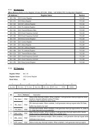
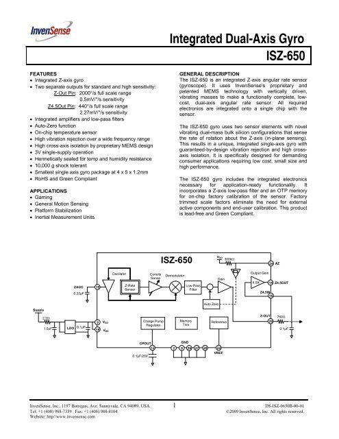
<strong>ISZ</strong>-<strong>650</strong>PIN DESCRIPTIONNumber Pin Description2, 8, 26, 27, 28 GND Ground9, 19 VDD Positive supply voltage12 CPOUT Charge pump capacitor connection14 Z4.5OUT Z-axis output of the 4.5X amplifier15 ZAGC Amplitude control capacitor connection16 Z4.5IN Z-axis input to the 4.5X amplifier20 Z-OUT Rate output for rotation about the Z-axis22 VREF Precision reference output23 PTATS Temperature Sensor Output24 AZ Auto Zero control pin10, 11, 13, 21, 25 RESV Reserved. Do not connect.1, 3, 4, 5, 6, 7, 17, 18 NC Not internally connected. May be used for PCB trace routing.PIN CONNECTION (TOP VIEW)RATE SENSITIVE AXISGNDGNDGNDRESVAZPTATSVREFRESVThis is a single-axis rate sensing device. It produces apositive output voltage for rotation about the Z-axis, asshown in the figure below.28 27 26 25 24 23 22 21NCGND122019Z-OUTVDDYNCNC341817NCNCNCNC561615Z4.5INZAGC+Z X7 8 9 10 11 12 13 14NCGNDVDDRESVRESVCPOUTRESVZ4.5OUT<strong>ISZ</strong>-<strong>650</strong>28-pin, 4mm x 5mm x 1.2mmQFN PackageInvenSense, Inc., 1197 Borregas Ave., Sunnyvale, CA 94089, USA 5 DS-<strong>ISZ</strong>-0<strong>650</strong>B-00-01Tel: +1 (408) 988-7339 Fax: +1 (408) 988-8104©2009 InvenSense, Inc. All rights reserved.Website: http//www.invensense.com
<strong>Integrated</strong> <strong>Dual</strong>-<strong>Axis</strong> <strong>Gyro</strong><strong>ISZ</strong>-<strong>650</strong>This information furnished by InvenSense is believed to be accurate and reliable. However, no responsibility is assumed by InvenSense for its use, or for any infringements of patents orother rights of third parties that may result from its use. Specifications are subject to change without notice. InvenSense reserves the right to make changes to this product, including itscircuits and software, in order to improve its design and/or performance, without prior notice. InvenSense makes no warranties, neither expressed nor implied, regarding the informationand specifications contained in this document. InvenSense assumes no responsibility for any claims or damages arising from information contained in this document, or from the use ofproducts and services detailed therein. This includes, but is not limited to, claims or damages based on the infringement of patents, copyrights, mask work and/or other intellectual propertyrights.Certain intellectual property owned by InvenSense and described in this document is patent protected. No license is granted by implication or otherwise under any patent or patent rights ofInvenSense. This publication supersedes and replaces all information previously supplied. Trademarks that are registered trademarks are the property of their respective companies.InvenSense sensors should not be used or sold in the development, storage, production or utilization of any conventional or mass-destructive weapons or any other weapons or lifethreatening applications, as well as in any other life critical applications such as medical equipment, transportation, aerospace and nuclear instruments, undersea equipment, power plantequipment, disaster prevention and crime prevention equipment.©2009 InvenSense, Inc. All rights reserved.InvenSense, Inc., 1197 Borregas, Ave. Sunnyvale, CA 94089, USA 8 DS-<strong>ISZ</strong>-0<strong>650</strong>B-00-01Tel: +1 (408) 988-7339 Fax: +1 (408) 988-8104©2009 InvenSense, Inc. All rights reserved.Website: http//www.invensense.com