RB-110 Users Manual - RoBoard
RB-110 Users Manual - RoBoard
RB-110 Users Manual - RoBoard

You also want an ePaper? Increase the reach of your titles
YUMPU automatically turns print PDFs into web optimized ePapers that Google loves.
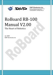
<strong>RoBoard</strong> <strong>RB</strong>‐<strong>110</strong><br />
<strong>Manual</strong> V1.00<br />
The Heart of Robotics<br />
Mar 2010<br />
DMP Electronics Inc
Copyright<br />
The information in this manual is subject to change without notice for continuous<br />
improvement in the product. All rights are reserved. The manufacturer assumes<br />
no responsibility for any inaccuracies that may be contained in this document.<br />
And makes no commitment to update or to keep current the information<br />
contained in this manual.<br />
No part of this manual may be reproduced, copied, translated or transmitted, in<br />
whole or in part, in any form or by any means without the prior written<br />
permission of the DMP Electronics Inc.<br />
Copyright 2010 DMP Electronics Inc.<br />
<strong>Manual</strong> No. RoBo<strong>110</strong>-01 Ver.1.0A Mar, 20101<br />
Trademarks Acknowledgment<br />
Vortex86DX is the registered trademark of DMP electronics Inc.<br />
Other brand names or product names appearing in this document are<br />
the properties and registered trademarks of their respective owners. All<br />
names mentioned herewith are served for identification purpose only.
T a b l e O f C o n t e n t s<br />
C h a p t e r 1 ............................................................................................ 4<br />
Introduction ........................................................................ 4<br />
1.1 Packing List.......................................................... 4<br />
1.2 Product Description.............................................. 5<br />
1.3 Specifications ....................................................... 6<br />
1.4 Board Dimension ................................................. 7<br />
C h a p t e r 2............................................................................................. 8<br />
Installation .......................................................................... 8<br />
2.1 Board Outline ....................................................... 8<br />
2.2 Connectors & Pin 1 Location ............................... 9<br />
2.3 Connectors & Jumpers Summary ...................... 10<br />
2.4 Pin Assignments ................................................. 11<br />
PWM .......................................................... 11<br />
J2: COM 3 Full Duplex TTL ........................ 11<br />
J3: USB -- 90 Deg ...................................... 11<br />
J4: USB ..................................................... 11<br />
J5: LAN ..................................................... 11<br />
J7: COM1 RS-232 ...................................... 12<br />
J8: COM2 RS-485 ...................................... 12<br />
J11: A/D 8Ch .............................................. 13<br />
J12: Power Connector (Board)(DC 6V-24V) 13<br />
J16: COM4 Full Duplex TTL ....................... 13<br />
J17: PWM initial Pull up/down switch ........ 13<br />
J18: I 2 C ...................................................... 14<br />
J19: Power Connector (PWM)(DC 6V-24V) . 14<br />
J20: COM5 Hi-Speed serial ........................ 14<br />
J22: COM6 Hi-Speed serial ........................ 14<br />
2.6 Watchdog Timer ................................................. 15<br />
C h a p t e r 3 ........................................................................................ 16<br />
Driver Installation ............................................................ 16<br />
A. Library, Sample and development code .............. 17
C h a p t e r 1<br />
Introduction<br />
1.1 Packing List<br />
Product Name<br />
Package<br />
<strong>RB</strong>-100<br />
<strong>RoBoard</strong> <strong>RB</strong>-10<br />
Cable-<strong>RB</strong>-100<br />
Power connector cable x 2<br />
COM port cable x 4 (4 Pin)<br />
COM port cable x 1 (10 Pin)<br />
I 2 C cable x 1<br />
LAN cable x 1<br />
2x5 pin Cable x 1<br />
<strong>RoBoard</strong> <strong>RB</strong>-<strong>110</strong> The Heart of Robotics www.<strong>RoBoard</strong>.com 4
1.2 Product Description<br />
The <strong>RoBoard</strong> is the heart of any Robotic system making your Robby more<br />
active and intelligent. It does not just offer control but is a complete computer<br />
system based on the Vortex86DX CPU, a 32bit x86 CPU running at 1000MHz<br />
with 256MB RAM.<br />
The <strong>RoBoard</strong> allows users to install a Windows or Linux Operating System onto<br />
a bootable Micro-SD card offering engineers a common storage media to<br />
develop with. The RoHS compliant CPU board measures just 96mm x 50mm<br />
and accepts a voltage input range from 6V-24V DC whilst providing extremely<br />
low power consumption.<br />
<strong>RoBoard</strong> has the rich I/O interfaces to the servo, DC motors, sensors,<br />
gyroscope, accelerometers and other devices. Also, it has build-in the PWM<br />
16 Ch, Hi-Speed serial, TTL serial, RS-485,USB V2.0 x 3, A/D convert, I 2 C bus,<br />
10/100M LAN and Mini PCI socket.<br />
<strong>RoBoard</strong> <strong>RB</strong>-<strong>110</strong> The Heart of Robotics www.<strong>RoBoard</strong>.com 5
1.3 Specifications<br />
CPU<br />
BIOS<br />
Memory<br />
ADCs<br />
Hi-Speed UART<br />
I /O Interface<br />
<strong>RB</strong>-100<br />
DM&P Vortex86DX- 1000MHz<br />
AMI BIOS<br />
256MB DDR2 onboard<br />
• Analog Devices AD-7918 10-bit<br />
• FTDI FT2232HL Hi-Speed UART<br />
• Micro SD slot x1<br />
• USB port x 1 (USB 2.0 version)<br />
Connectors • 2.54 mm 3-pin box header for PWM x 16<br />
• 2.54 mm 10-pin box header for RS-232 x 1<br />
• 2.54 mm 10 pin box header for Hi-speed (COM 6) x 1<br />
• 2.0 mm 4 pin header for High speed (COM 5) x 1<br />
• 2.0 mm 4-pin header for RS-485 x 1<br />
• 2.0 mm 4-pin header for TTL serial x 2<br />
• 1.25mm 6-pin wafer for I2C x 1<br />
• 2.54 mm 16-pin header for A/D x 1<br />
• 2.54 mm 10-pin box header for USB x 1<br />
• 1.25 mm 4-pin wafer for LAN x 1<br />
• 1.25mm 6-pin wafer for JTAG x 1<br />
• 0.8mm 124-Pin Mini PCI Card connector<br />
• 3.96 mm 2 pin for Power x 2<br />
Resolution<br />
Power<br />
Consumption<br />
Power Input<br />
Dimension<br />
Weight<br />
PWM : 20ns<br />
Serial : 115200bps ~ 750Kbps (COM 1, 2, 3 & 4)<br />
High Speed Serial : Up to 12Mbps (COM 5 & COM 6)<br />
I 2 C : 1Kbps ~ 3.3Mbps<br />
+5V @ 400mA<br />
DC-in 6V to 24V<br />
96mm X 56mm<br />
40g<br />
<strong>RoBoard</strong> <strong>RB</strong>-<strong>110</strong> The Heart of Robotics www.<strong>RoBoard</strong>.com 6
1.4 Board Dimension<br />
<strong>RoBoard</strong> <strong>RB</strong>-<strong>110</strong> The Heart of Robotics www.<strong>RoBoard</strong>.com 7
C h a p t e r 2<br />
Installation<br />
2.1 Board Outline<br />
<strong>RoBoard</strong> <strong>RB</strong>-<strong>110</strong> The Heart of Robotics www.<strong>RoBoard</strong>.com 8
2.2 Connectors & Pin 1 Location<br />
Connectors<br />
Pin 1 Location<br />
<strong>RoBoard</strong> <strong>RB</strong>-<strong>110</strong> The Heart of Robotics www.<strong>RoBoard</strong>.com 9
2.3 Connectors & Jumpers Summary<br />
Summary Table<br />
Description Type of Connections Pin<br />
J1 Micro-SD Slot Micro-SD slot 13-pin<br />
J2 COM 3 TTL Box Header,2.0mm , 4x1 4-pin<br />
J3 USB USB 90 Deg 4-pin<br />
J4 USB x 2 Pin Header, 2,54mm, 5x2 10-Pin<br />
J5 LAN Wafer, 1,25mm, 4x1 4-pin<br />
J6 JTAG Wafer, 2.54mm,6x1 6-pin<br />
J7 COM1 Pin Header, 2.54mm,5x2 10-pin<br />
J18 RS-485 Box Header,2.0mm , 4x1 4-pin<br />
J11 A/D 8Ch Box Header, 2.54mm, 8x2 16-pin<br />
J12 Power Connector (Board) Pin Header, 3.96mm 2-pin<br />
J13 Mini PCI Socket Mini PCI Type III 124-pin<br />
J16 COM4 TTL Box Header,2.0mm , 4x1 4-pin<br />
J17 PWM initial pull up/down switch DIP switch<br />
J8 I 2 C Wafer, 1,25mm, 6x1 6-pin<br />
J19 Power Connector (PWM) Pin Header, 3.96mm 2-pin<br />
J20 COM 5 Hi-Speed (Port 1) Box Header,2.0mm , 4x1 4-pin<br />
J22 COM 6 Hi-Speed (Port 2) Pin Header, 2.54mm,5x2 10-pin<br />
<strong>RoBoard</strong> <strong>RB</strong>-<strong>110</strong> The Heart of Robotics www.<strong>RoBoard</strong>.com 10
2.4 Pin Assignments<br />
PWM<br />
Signal<br />
Signal<br />
Signal<br />
Pin #<br />
Pin #<br />
Pin #<br />
Name<br />
Name<br />
Name<br />
1 GND 2 Vxx 3 GPxx<br />
J2: COM 3 Full Duplex TTL<br />
Pin #<br />
Signal<br />
Signal<br />
Pin #<br />
Name<br />
Name<br />
1 GND 2 Vxx<br />
3 TXD3 4 RXD3<br />
J3: USB -- 90 Deg<br />
Pin # Signal Name Pin # Signal Name<br />
1 VCC 2 LUSBD2-<br />
3 LUSBD2+ 4 GND<br />
J4: USB<br />
Pin # Signal Name Pin # Signal Name<br />
1 VCC 2 VCC<br />
3 LUSBD0- 4 LUSBD1-<br />
5 LUSBD0+ 6 LUSBD1+<br />
7 GND 8 GND<br />
9 GGND 10 GGND<br />
J5: LAN<br />
Pin # Signal Name Pin # Signal Name<br />
1 LAN-TX+ 2 LAN-TX-<br />
3 LAN-RX+ 4 LAN-RX-<br />
<strong>RoBoard</strong> <strong>RB</strong>-<strong>110</strong> The Heart of Robotics www.<strong>RoBoard</strong>.com 11
J6: JTAG<br />
Pin # Signal Name Pin # Signal Name<br />
1 VCC 2 GND<br />
3 TCK 4 TDO<br />
5 TDI 6 TMS<br />
J7: COM1 RS-232<br />
Pin #<br />
Signal<br />
Signal<br />
Pin #<br />
Name<br />
Name<br />
1 DCD1 2 RXD1<br />
3 TXD1 4 DTR1<br />
5 GND 6 DSR1<br />
7 RTS1 8 CTS1<br />
9 RI1 10 NC<br />
J8: COM2 RS-485<br />
Pin #<br />
Signal<br />
Name<br />
Pin #<br />
Signal<br />
Name<br />
1 GND 2 Vxx<br />
3 RS-485+ 4 RS-485-<br />
<strong>RoBoard</strong> <strong>RB</strong>-<strong>110</strong> The Heart of Robotics www.<strong>RoBoard</strong>.com 12
J11: A/D 8Ch<br />
Pin #<br />
Signal<br />
Name<br />
Pin # Signal Name<br />
1 AD-VIN0 2 ADGND<br />
3 AD-VIN1 4 ADGND<br />
5 AD-VIN2 6 ADGND<br />
7 AD-VIN3 8 ADGND<br />
9 AD-VIN4 10 ADGND<br />
11 AD-VIN5 12 ADGND<br />
13 AD-VIN6 14 ADGND<br />
15 AD-VIN7 16 ADGND<br />
J12: Power Connector (Board)(DC 6V-24V)<br />
Pin # Signal Name<br />
1 Vxx<br />
2 GND<br />
J16: COM4 Full Duplex TTL<br />
Pin #<br />
Signal<br />
Signal<br />
Pin #<br />
Name<br />
Name<br />
1 GND 2 Vxx<br />
3 TXD4 4 RXD4<br />
J17: PWM initial Pull up/down switch<br />
Pin # Signal Name Pin # Signal Name<br />
1 PWM init Pull UP 2 PWM init Pull Down<br />
<strong>RoBoard</strong> <strong>RB</strong>-<strong>110</strong> The Heart of Robotics www.<strong>RoBoard</strong>.com 13
J18: I 2 C<br />
Pin #<br />
Signal<br />
Signal<br />
Pin #<br />
Name<br />
Name<br />
1 Vcc 2 GND<br />
3 SCL 4 SDA<br />
5 Reset 6 3.3V out<br />
J19: Power Connector (PWM)(DC 6V-24V)<br />
Pin # Signal Name<br />
1 Vxx<br />
2 GND<br />
J20: COM5 Hi-Speed serial (Port 1)<br />
Pin #<br />
Signal<br />
Signal<br />
Pin #<br />
Name<br />
Name<br />
1 GND 2 Vxx<br />
3 TXD5 4 RXD5<br />
J22: COM6 Hi-Speed serial (Port 2)<br />
Pin #<br />
Signal<br />
Signal<br />
Pin #<br />
Name<br />
Name<br />
1 DCD6 2 RXD6<br />
3 TXD6 4 DTR6<br />
5 GND 6 DSR6<br />
7 RTS6 8 CTS6<br />
9 RI6 10 TXDEN6<br />
<strong>RoBoard</strong> <strong>RB</strong>-<strong>110</strong> The Heart of Robotics www.<strong>RoBoard</strong>.com 14
2.6 Watchdog Timer<br />
There are two watchdog timers in Vortex86DX CPU. One is<br />
compatible with M6117D watchdog timer and the other is new. The<br />
M6117D compatible watchdog timer is called WDT0 and new one<br />
is called WDT1.<br />
We also provide DOS, Linux and WinCE example for your<br />
reference. For more technical support, please visit:<br />
http://www.dmp.com.tw/tech or download the PDF file:<br />
http://www.dmp.com.tw/tech/vortex86dx/<br />
<strong>RoBoard</strong> <strong>RB</strong>-<strong>110</strong> The Heart of Robotics www.<strong>RoBoard</strong>.com 15
C h a p t e r 3<br />
Driver Installation<br />
VGA<br />
The Vortex86DX processor also use external Display chip ““Volari Z9s” which<br />
is an ultra low powered graphics chipset with total power consumption at around<br />
1-1.5 W. It is capable in providing VGA display output up to 1600x1200. With<br />
DVO interface, developers could easily connect flat Panel to support TFT and<br />
LVDS output.<br />
LAN<br />
The Vortex86DX processor also integrated 10/100Mbps Ethernet controller that<br />
supports both 10/100BASE-T and allows direct connection to your 10/100Mbps<br />
Ethernet based Local Area Network for full interaction with local servers, wide<br />
area networks such as the Internet.<br />
AUDIO<br />
CM119 is a highly integrated single chip USB audio controller specifically for<br />
VoIP (Voice over internet protocol) application. All essential analog modules are<br />
embedded in CM119, including dual DAC and earphone driver, ADC,<br />
microphone booster, PLL, regulator, and USB transceiver.<br />
The <strong>RB</strong>-100 provides the VGA and LAN drivers for Windows XP, Windows CE<br />
5.0 and Windows Embedded CE 6.0R2 and Windows Embedded Standard<br />
(XPe). Please get from official website: http://www.roboard.com<br />
The <strong>RB</strong>-100 also supports most of the popular Linux distributions, for more<br />
detail information, please visit DMP official website:<br />
http://www.dmp.com.tw/tech/vortex86dx/<br />
<strong>RoBoard</strong> <strong>RB</strong>-<strong>110</strong> The Heart of Robotics www.<strong>RoBoard</strong>.com 16
A. Library, Sample and development code<br />
The <strong>RB</strong>-100 provides the Library, sample and development code. Please<br />
download from official website: http://www.roboard.com<br />
<strong>RoBoard</strong> <strong>RB</strong>-<strong>110</strong> The Heart of Robotics www.<strong>RoBoard</strong>.com 17
Warranty<br />
This product is warranted to be in good working order for a period of one year<br />
from the date of purchase. Should this product fail to be in good working order at<br />
any time during this period, we will, at our option, replace or repair it at no<br />
additional charge except as set forth in the following terms. This warranty does<br />
not apply to products damaged by misuse, modifications, accident or disaster.<br />
Vendor assumes no liability for any damages, lost profits, lost savings or any<br />
other incidental or consequential damage resulting from the use, misuse of,<br />
originality to use this product. Vendor will not be liable for any claim made by<br />
any other related party. Return authorization must be obtained from the vendor<br />
before returned merchandise will be accepted. Authorization can be obtained by<br />
calling or faxing the vendor and requesting a Return Merchandise Authorization<br />
(RMA) number. Returned goods should always be accompanied by a clear<br />
problem description.<br />
<strong>RoBoard</strong> <strong>RB</strong>-<strong>110</strong> The Heart of Robotics www.<strong>RoBoard</strong>.com 18