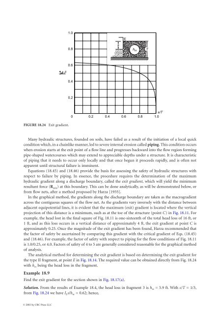
<strong>18</strong>-24 The Civil Engineering H<strong>and</strong>book, Second Edition1.0E0.8sh mT0.6l sEh m0.40.20s/T0.2 0.4 0.6 0.8 1.0FIGURE <strong>18</strong>.24 Exit gradient.Many hydraulic structures, founded on soils, have failed as a result of the initiation of a local quickcondition which, in a chainlike manner, led to severe internal erosion called piping. This condition occurswhen erosion starts at the exit point of a flow line <strong>and</strong> progresses backward into the flow region formingpipe-shaped watercourses which may extend to appreciable depths under a structure. It is characteristicof piping that it needs to occur only locally <strong>and</strong> that once begun it proceeds rapidly, <strong>and</strong> is often notapparent until structural failure is imminent.Equations (<strong>18</strong>.45) <strong>and</strong> (<strong>18</strong>.46) provide the basis for assessing the safety of hydraulic structures withrespect to failure by piping. In essence, the procedure requires the determination of the maximumhydraulic gradient along a discharge boundary, called the exit gradient, which will yield the minimumresultant force (R min ) at this boundary. This can be done analytically, as will be demonstrated below, orfrom flow nets, after a method proposed by Harza [1935].In the graphical method, the gradients along the discharge boundary are taken as the macrogradientacross the contiguous squares of the flow net. As the gradients vary inversely with the distance betweenadjacent equipotential lines, it is evident that the maximum (exit) gradient is located where the verticalprojection of this distance is a minimum, such as at the toe of the structure (point C) in Fig. <strong>18</strong>.11. Forexample, the head lost in the final square of Fig. <strong>18</strong>.11 is one-sixteenth of the total head loss of 16 ft, or1 ft, <strong>and</strong> as this loss occurs in a vertical distance of approximately 4 ft, the exit gradient at point C isapproximately 0.25. Once the magnitude of the exit gradient has been found, Harza recommended thatthe factor of safety be ascertained by comparing this gradient with the critical gradient of Eqs. (<strong>18</strong>.45)<strong>and</strong> (<strong>18</strong>.46). For example, the factor of safety with respect to piping for the flow conditions of Fig. <strong>18</strong>.11is 1.0/0.25, or 4.0. Factors of safety of 4 to 5 are generally considered reasonable for the graphical methodof analysis.The analytical method for determining the exit gradient is based on determining the exit gradient forthe type II fragment, at point E in Fig. <strong>18</strong>.14. The required value can be obtained directly from Fig. <strong>18</strong>.24with h m being the head loss in the fragment.Example <strong>18</strong>.9Find the exit gradient for the section shown in Fig. <strong>18</strong>.17(a).Solution. From the results of Example <strong>18</strong>.4, the head loss in fragment 3 is h m = 5.9 ft. With s/T = 1/3,from Fig. <strong>18</strong>.24 we have I E s/h m = 0.62; hence,© 2003 by CRC Press LLC
<strong>Groundwater</strong> <strong>and</strong> <strong>Seepage</strong> <strong>18</strong>-25To account for the deviations <strong>and</strong> uncertainties in nature, Khosla et al. [1954] recommend that thefollowing factors of safety be applied as critical values of exit gradients: gravel, 4 to 5; coarse s<strong>and</strong>, 5 to6; <strong>and</strong> fine s<strong>and</strong>, 6 to 7.The use of reverse filters on the downstream surface or where required serves to prevent erosion <strong>and</strong>decrease the probability of piping failures. In this regard, the Earth Manual of the U.S. Bureau ofReclamation, Washington [1974] is particularly recommended.Defining TermsCoefficient of permeability — Coefficient of proportionality between Darcy’s velocity <strong>and</strong> the hydraulicgradient.Flow net — Trial-<strong>and</strong>-error graphical procedure for solving seepage problems.Hydraulic gradient — Space rate of energy dissipation.Method of fragments — Approximate analytical method for solving seepage problems.Piping — Development of a “pipe” within soil by virtue of internal erosion.Quick condition — Condition when soil “liquifies.”References0.62 ¥ 5.91I E = ---------------------- = 0.41 or FS = --------- = 2.4490.41Bear, J. 1972. Dynamics of Fluids in Porous Media. American Elsevier, New York.Bear, J., Zaslavsky, D., <strong>and</strong> Irmay, S. 1966. Physical Principles of Water Percolation <strong>and</strong> <strong>Seepage</strong>. Technion,Israel.Brahma, S. P., <strong>and</strong> Harr, M. E. 1962. Transient development of the free surface in a homogeneous earthdam. Geotechnique. 12(4).Casagr<strong>and</strong>e, A. 1940. <strong>Seepage</strong> Through Dams. In Contributions to Soil Mechanics 1925–1940. BostonSociety of Civil Engineering, Boston.Cedergren, H. R. 1967. <strong>Seepage</strong>, Drainage <strong>and</strong> Flow Nets. John Wiley & Sons, New York.Dachler, R. 1934. Ueber den Strömungsvorgang bei Hanquellen. Die Wasserwirtschaft, no. 5.Darcy, H. <strong>18</strong>56. Les Fontaines publique de la ville de Dijon. Paris.Domenico, P. A., <strong>and</strong> Schwartz, F. W. 1990. Physical <strong>and</strong> Chemical Hydrogeology. John Wiley & Sons, NewYork.Dvinoff, A. H., <strong>and</strong> Harr, M. E. 1971. Phreatic surface location after drawdown. J. Soil Mech. Found.ASCE. January.Earth Manual. 1974. Water Resources Technology Publication, 2nd ed. U.S. Department of Interior, Bureauof Reclamation, Washington, D.C.Forchheimer, P. 1930. Hydraulik. Teubner Verlagsgesellschaft, Stuttgart.<strong>Free</strong>ze, R. A., <strong>and</strong> Cherry, J. A. 1979. <strong>Groundwater</strong>. Prentice-Hall, Englewood Cliffs, NJ.Harr, M. E. 1962. <strong>Groundwater</strong> <strong>and</strong> <strong>Seepage</strong>. McGraw-Hill, New York.Harr, M. E., <strong>and</strong> Lewis, K. H. 1965. <strong>Seepage</strong> around cutoff walls. RILEM, Bulletin 29, December.Harr, M. E. 1977. Mechanics of Particulate Media: A Probabilistic Approach. McGraw-Hill, New York.Harza, L. F. 1935. Uplift <strong>and</strong> seepage under dams on s<strong>and</strong>. Trans. ASCE, vol. 100.Khosla, R. B. A. N., Bose, N. K., <strong>and</strong> Taylor, E. M. 1954. Design of Weirs on Permeable Foundations. CentralBoard of Irrigation, New Delhi, India.Lambe, H. 1945. Hydrodynamics. Dover, New York.Muskat, M. 1937. The Flow of Homogeneous Fluids through Porous Media. McGraw-Hill, New York.Reprinted by J. W. Edwards, Ann Arbor, 1946.Pavlovsky, N. N. 1956. Collected Works. Akad. Nauk USSR, Leningrad.Polubarinova-Kochina, P. Ya. 1941. Concerning seepage in heterogeneous (two-layered) media. InzhenerniiSbornik. 1(2).© 2003 by CRC Press LLC