Chapter 18: Groundwater and Seepage - Free
Chapter 18: Groundwater and Seepage - Free
Chapter 18: Groundwater and Seepage - Free

You also want an ePaper? Increase the reach of your titles
YUMPU automatically turns print PDFs into web optimized ePapers that Google loves.
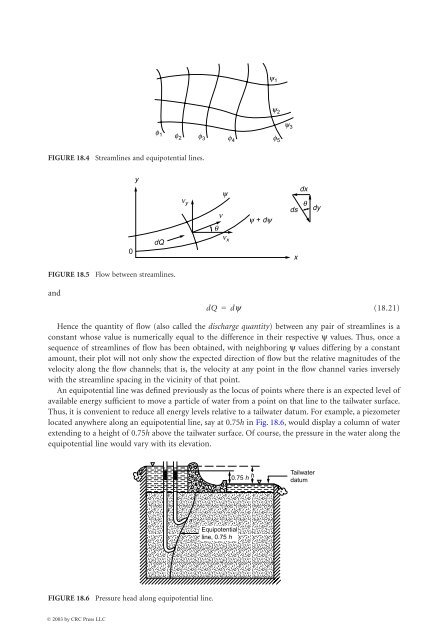
<strong>18</strong>-8 The Civil Engineering H<strong>and</strong>book, Second Editiony 1y 2y 3f 1f 2f 3f 4f 5FIGURE <strong>18</strong>.4 Streamlines <strong>and</strong> equipotential lines.yn yynqy + dydxdsqdy0dQn xxFIGURE <strong>18</strong>.5 Flow between streamlines.<strong>and</strong>dQ=dy(<strong>18</strong>.21)Hence the quantity of flow (also called the discharge quantity) between any pair of streamlines is aconstant whose value is numerically equal to the difference in their respective y values. Thus, once asequence of streamlines of flow has been obtained, with neighboring y values differing by a constantamount, their plot will not only show the expected direction of flow but the relative magnitudes of thevelocity along the flow channels; that is, the velocity at any point in the flow channel varies inverselywith the streamline spacing in the vicinity of that point.An equipotential line was defined previously as the locus of points where there is an expected level ofavailable energy sufficient to move a particle of water from a point on that line to the tailwater surface.Thus, it is convenient to reduce all energy levels relative to a tailwater datum. For example, a piezometerlocated anywhere along an equipotential line, say at 0.75h in Fig. <strong>18</strong>.6, would display a column of waterextending to a height of 0.75h above the tailwater surface. Of course, the pressure in the water along theequipotential line would vary with its elevation.0.75 h hTailwaterdatumbaEquipotentialline, 0.75 hFIGURE <strong>18</strong>.6 Pressure head along equipotential line.© 2003 by CRC Press LLC