Steering Catalog - Eaton Corporation
Steering Catalog - Eaton Corporation
Steering Catalog - Eaton Corporation

You also want an ePaper? Increase the reach of your titles
YUMPU automatically turns print PDFs into web optimized ePapers that Google loves.
<strong>Steering</strong> <strong>Catalog</strong><br />
<strong>Steering</strong> Control Units<br />
Torque Generators<br />
<strong>Steering</strong> Columns
The Power of One <strong>Eaton</strong><br />
HANSEN <br />
GROMELLE <br />
There’s a certain energy at <strong>Eaton</strong>. It’s the power of integrating<br />
the competencies of some of the world’s most respected<br />
names to build a brand you can trust to meet every<br />
power management need. The energy created supports<br />
our commitment to powering business worldwide.<br />
As the world’s demand for high-efficiency hydraulic<br />
systems for mobile and stationary applications increase,<br />
<strong>Eaton</strong> is helping to solve these challenges more reliably,<br />
efficiently, and sustainably. Our goal is simple; to provide<br />
unique solutions across a wide range of markets that<br />
keep businesses on the leading edge of change. Visit<br />
<strong>Eaton</strong>.com/hydraulics/fusion.<br />
That’s the power of One <strong>Eaton</strong>.
Serving eight key segments - sharing one focus<br />
Alternative Energy<br />
Discrete Manufacturing<br />
Making energy sources technically Produce at peak efficiency with<br />
practical and economically sound the superior precision and<br />
requires the kind of control repeatability of <strong>Eaton</strong> products.<br />
made possible by high-quality <strong>Eaton</strong> hydraulic components<br />
components. When <strong>Eaton</strong> is on provide the precise control and<br />
the inside, you will experience the consistent operation required<br />
reliable, consistent performance for virtually every step in your<br />
to create and capture energy— manufacturing operation. With<br />
making renewable energy an <strong>Eaton</strong>, we’ll help you redefine<br />
every-day energy.<br />
the meaning of raw productivity.<br />
Agriculture & Forestry<br />
Commercial Vehicles<br />
There’s a reason farming and <strong>Eaton</strong> technologies can make<br />
forestry are called “working the your driving operation more<br />
land.” These segments involve successful. Greater comfort<br />
some of the hardest work and and productivity help increase<br />
longest hours of any sector in driver retention, while reduced<br />
the economy. Your productivity emissions, leaks, and noise<br />
and profitability depend on the improve environmental<br />
way you manage time and tasks. performance. Increased<br />
efficiencies overall mean lower<br />
costs and higher net revenue.<br />
<strong>Eaton</strong> is a leading diversified<br />
power management company<br />
Understanding and helping our customers succeed<br />
• Listening and understanding to requirements and<br />
business drivers<br />
• Delivering solutions with value propositions to solve the<br />
critical business needs<br />
Knowing what’s important to our customers and<br />
integrating that knowledge into the fabric of our business<br />
• …to deliver innovative, quality products<br />
• …to respond fast<br />
• …to provide dedicated customer service and support<br />
around the globe<br />
Oil & Gas<br />
Processing<br />
As the oil & gas industry continues Whatever your industry, no matter<br />
to face further globalization which processes you manage,<br />
and consolidation, large-scale <strong>Eaton</strong> parts and systems help<br />
organizations that can meet your keep you up and running. Our<br />
needs in every corner of the world components make equipment more<br />
are more difficult to find. At <strong>Eaton</strong>, efficient and easier to use, so you<br />
our portfolio of products is only get optimal machine performance<br />
surpassed by our tremendous<br />
reach.<br />
and maximum productivity.<br />
Material Handling<br />
Construction & Mining<br />
<strong>Eaton</strong> hydraulic systems provide When you work on a large scale,<br />
the precise control and<br />
even the details are big. You<br />
consistent operation required need to trust every part of the<br />
for material handling and utility equipment that lets you handle<br />
work. With a broad selection of construction and mining jobs.<br />
products and solutions built in, For reliable components that<br />
<strong>Eaton</strong> helps make you a master deliver consistent performance in<br />
of your domain.<br />
extreme conditions, turn to <strong>Eaton</strong>.<br />
<strong>Eaton</strong> provides reliable,<br />
efficient and safe power<br />
management for a growing<br />
number of industries.<br />
Our strength is global reach with local responsiveness<br />
and support<br />
• Customers served in more than 150 countries<br />
• Diverse channels ensure reliable availability and support<br />
• Design and engineering teams provide support for<br />
standard products and custom solutions<br />
• <strong>Eaton</strong> experts offer efficient product and application<br />
training
Literature Referenced in this <strong>Catalog</strong>:<br />
• <strong>Eaton</strong> Technical Bulletin 3-401<br />
• <strong>Eaton</strong> Flow Divider <strong>Catalog</strong> E-VLFL-MC001-E<br />
• <strong>Eaton</strong> Relief Valve <strong>Catalog</strong> 11-510<br />
• <strong>Eaton</strong> Gear Pumps Series 26 Model 26000<br />
<strong>Catalog</strong> 11-609<br />
• <strong>Eaton</strong> Char-Lynn Low Speed High Torque Motors<br />
<strong>Catalog</strong> E-MOLO-MC001-E2<br />
• Vickers® Screw in Cartridge Values<br />
<strong>Catalog</strong> V-VLOV-MC001-E2<br />
• Vickers® Proportional Valves <strong>Catalog</strong> 539<br />
• Vickers Solenoid Operated Directional Valves<br />
<strong>Catalog</strong> GB-C-2015<br />
4<br />
EATON <strong>Steering</strong> <strong>Catalog</strong> C-STOV-MC001-E2 September 2011
Table of Contents<br />
Description and Technologies About Power <strong>Steering</strong><br />
Description and Advantages ............................................................................................................................................. 7<br />
Hydraulic Circuit Explanation ........................................................................................................................................ 9-14<br />
Neutral Circuits<br />
Open Center .......................................................................................................................................... 9<br />
Open Center Power Beyond .................................................................................................................. 9<br />
Closed Center ...................................................................................................................................... 10<br />
Load Sensing (static and dynamic signal) ............................................................................................ 11<br />
Work Circuits<br />
Non-Load Reaction............................................................................................................................... 14<br />
Load Reaction ...................................................................................................................................... 14<br />
<strong>Steering</strong> Units with Integral Valves ................................................................................................................................. 15<br />
Special Features and Application ............................................................................................................................... 16-21<br />
Manual <strong>Steering</strong>. ............................................................................................................................................... 16<br />
2 Speed ............................................................................................................................................................. 17<br />
Dual Displacement ............................................................................................................................................ 18<br />
<strong>Eaton</strong> Technologies<br />
Q-Amp (Flow Amplification) .............................................................................................................................. 19<br />
Wide Angle ....................................................................................................................................................... 21<br />
Cylinder Damping.............................................................................................................................................. 22<br />
VersaSteer ........................................................................................................................................................ 23<br />
STC Direct Porting ............................................................................................................................................ 24<br />
<strong>Steering</strong> Control Units and Torque Generators<br />
Series 5 ............................................................................................................................................................. 25<br />
Series 10 ........................................................................................................................................................... 32<br />
Series 20 ........................................................................................................................................................... 40<br />
Series 25 ........................................................................................................................................................... 47<br />
Series 40 ........................................................................................................................................................... 52<br />
Torque Generator .............................................................................................................................................. 56<br />
<strong>Steering</strong> System Components and System Accessories<br />
Antijerk Valves .................................................................................................................................................. 67<br />
Priority Valves VLC, VLE, VLH ........................................................................................................................... 68<br />
Check Valves..................................................................................................................................................... 72<br />
Relief Valves ..................................................................................................................................................... 74<br />
Columns ............................................................................................................................................................ 75<br />
<strong>Steering</strong> Wheels and Accessories .................................................................................................................... 85<br />
EH Proportional Steer Valves ............................................................................................................................ 88<br />
Four Wheel Steer Switching Valves .................................................................................................................. 89<br />
Flow Divider Valves........................................................................................................................................... 90<br />
Brake Valves ..................................................................................................................................................... 91<br />
T Series Hydraulic Motors................................................................................................................................. 92<br />
EATON <strong>Steering</strong> <strong>Catalog</strong> C-STOV-MC001-E2 September 2011 5
Sizing and Application<br />
Ackermann Type <strong>Steering</strong>................................................................................................................................. 92<br />
Articulated Type <strong>Steering</strong>.................................................................................................................................. 95<br />
Articulated Vehicle <strong>Steering</strong> Analysis Form ...................................................................................................... 96<br />
Articulated Vehicle <strong>Steering</strong> Analysis Form ...................................................................................................... 98<br />
Information contained in this publication is accurate as of the publication<br />
date and is subject to change without notice. Performance values are typical<br />
values. Customers are responsible for selecting products for their applications<br />
using normal engineering methods.<br />
6<br />
EATON <strong>Steering</strong> <strong>Catalog</strong> C-STOV-MC001-E2 September 2011
Description and Advantages<br />
<strong>Steering</strong> Control Units<br />
The Char-Lynn ® steering control unit (SCU) is fully fluid linked.<br />
This means there is no mechanical connection between the<br />
steering unit, the pump and the steering cylinders. The unit<br />
consists of a manually operated directional control servo<br />
valve and feedback meter element in a single body. It is used<br />
principally for fluid linked power steering systems but it can<br />
be used for some servo-type applications or any application<br />
where visual positioning is required. The close coupled, rotary<br />
action valve performs all necessary fluid directing functions<br />
with a small number of moving parts. The manually actuated<br />
valve is coupled with the mechanical drive to the meter gear.<br />
The control is lubricated and protected by the power fluid in<br />
the system and can operate in many environments.<br />
Char-Lynn power steering control units offer the following<br />
advantages:<br />
• Minimizes steering linkage—reduces cost, provides flexibility<br />
in design.<br />
• Provides complete isolation of load forces from the control<br />
station—provides operator comfort.<br />
• Provides continuous, unlimited control action with very<br />
low input torque.<br />
• Provides a wide selection of control circuits and meter<br />
sizes.<br />
• Can work with many kinds of power steering pumps or<br />
fluid supply.<br />
SERIES 5 (291-XXXX-XXX, 292-XXXX-XXX, 293-XXXX-XXX, 294-XXXX-XXX)<br />
Displacement 31.5 - 146 cm3 /r 1.92 - 8.9 in3 /r<br />
Flow 11 - 19 l/min 3 - 5 GPM<br />
Pressure 140 bar 2030 PSI<br />
SERIES 10 (200-XXXX-XXX, 220-XXXX-XXX)<br />
Displacement 58.7 - 739 cm3 /r 3.58 - 45.1 in3 /r<br />
Flow 11 - 76 l/min 3 - 20 GPM<br />
Pressure 275 bar 4000 PSI<br />
SERIES 20 (236-XXXX-XXX)<br />
Displacement 60 - 985 cm3 /r 3.6 - 60 in3 /r<br />
Flow 38 - 114 l/min 10 - 30 GPM<br />
Pressure 241 bar 3500 PSI<br />
SERIES 25 (251-XXXX-XXX, 252-XXXX-XXX, 253-XXXX-XXX)<br />
Displacement 490 - 1230 cm3 /r 30 - 75 in3 /r<br />
Flow 95 - 151 l/min 25 - 40 GPM<br />
Pressure 241 bar 3500 PSI<br />
SERIES 40 (281-XXXX-XXX, 282-XXXX-XXX, 283-XXXX-XXX)*<br />
Displacement 1230 - 3030 cm3 /r 75 - 185 in3 /r<br />
Flow 151 - 227 l/min 40 - 60 GPM<br />
Pressure 241 bar 3500 PSI<br />
* For all other product numbers consult steering website.<br />
EATON <strong>Steering</strong> <strong>Catalog</strong> C-STOV-MC001-E2 September 2011 7
Description and Advantages<br />
Torque Generator<br />
Char-Lynn torque generators have been completely redesigned<br />
to meet the needs of the changing marketplace.<br />
These torque generators have served the industry well,<br />
providing:<br />
• Power assist for vehicle steering<br />
• Power assist on gates and valves, eliminating the large<br />
hand wheels<br />
• Powerful rotary motion with effortless manual rotary<br />
input on numerous other applications<br />
Today’s market includes power steering on electric lift trucks.<br />
These new torque generators have been designed with features<br />
that greatly improve the operator’s comfort as well as<br />
the vehicle’s performance.<br />
Use the Torque Generator as rotary power assist for:<br />
• Large indexing tables<br />
• Manually operated gates and valves<br />
• Manual positioning devices<br />
• Mechanical steering systems<br />
• Turntables<br />
Customized <strong>Steering</strong> Columns<br />
Char-Lynn columns can be custom built to your exact specifications.<br />
The column and mounting flange is of a sturdy single<br />
weldment design. These columns have high thrust and side<br />
load capacity with low shaft torsional friction. A tilt column is<br />
also available.<br />
8<br />
EATON <strong>Steering</strong> <strong>Catalog</strong> C-STOV-MC001-E2 September 2011<br />
SERIES 217, 227<br />
Displacement 76 - 160 cm3 /r 4.7 - 9.6 in3 /r<br />
Flow 15 l/min 4 GPM<br />
Pressure 69 and 172 bar 1000 and 2500 PSI<br />
STEERING COLUMNS (204-XXXX-XXX)<br />
Jacket Length 56 - 836 mm 2.2 - 33 inch<br />
Horn Wire with and without with and without<br />
Upper Ends 10 Upper End Types 10 Upper End Types
Hydraulic Circuit Explanation<br />
Neutral Circuits: Open Center and Open Center<br />
Power Beyond<br />
Open Center<br />
• Simplest, most economical system<br />
• Uses a fixed displacement pump<br />
• In neutral position pump and tank are connected<br />
• Most suitable on smaller type vehicles<br />
Open Center Power Beyond<br />
The power beyond steering control unit supplies steering and<br />
auxiliary valve functions. The power beyond unit is used on<br />
medium pressure, open center (fixed displacement pump)<br />
systems. When not steering, the power beyond unit directs<br />
all inlet flow to the auxiliary circuit. However once steering<br />
is initiated, part of the auxiliary flow is diverted to steering.<br />
Since steering has priority, all flow, if required, will be diverted<br />
to steering. The tank port of the steering unit has flow<br />
only when steering is operated. Thus, flow out of the auxiliary<br />
(“PB”) port and the tank port will fluctuate or stop depending<br />
on steering input.<br />
The following special considerations should be addressed<br />
when applying power beyond steering:<br />
• Auxiliary valves (connected to PB) must be open center<br />
type. Slight bump or kick may be felt in steering wheel<br />
when auxiliary functions are activated during steering<br />
operations.<br />
• Pump flow not used for steering is available at power<br />
beyond (PB) outlet, except at steering stops where total<br />
pump flow goes over the system relief valve. Avoid auxiliary<br />
functions that require constant flow while steering.<br />
• Flow is only directed to the tank port when steering is<br />
operated. Avoid systems where return flow from tank<br />
port is used for auxiliary functions.<br />
• Inlet pressure to the steering unit will be the higher of<br />
steering system pressure or auxiliary valve pressure.<br />
• Generally avoid systems where heavy use of auxiliary<br />
functions occur while steering.<br />
Applications<br />
• Lawn and Garden Equipment<br />
• Utility Vehicles<br />
Gerotor<br />
Gerotor<br />
L R<br />
T<br />
L R<br />
T<br />
P<br />
PB P<br />
Fixed<br />
Displacement<br />
Pump<br />
Fixed<br />
Displacement<br />
Pump<br />
To Auxilliary Circuit<br />
Open Center Valves<br />
EATON <strong>Steering</strong> <strong>Catalog</strong> C-STOV-MC001-E2 September 2011 9
Hydraulic Circuit Explanation<br />
Neutral Circuits: Closed Center<br />
Closed Center<br />
• Uses a pressure compensated variable displacement<br />
pump<br />
• In neutral position pump and tank are disconnected<br />
• Most suitable on large construction equipment<br />
Closed Center with Neutral Bleed<br />
Neutral Bleed Feature<br />
Closed Center <strong>Steering</strong> Control Units are available with and<br />
without neutral bleed feature. Most applications may not require<br />
the bleed feature, however, the maximum temperature<br />
differential between components within the steering circuit<br />
must not exceed specification (50° F or 28° C). Order unit<br />
with the bleed feature if the temperature differential may exceed<br />
this limit. The neutral bleed feature allows a small flow<br />
of fluid to pass through the unit when in neutral to reduce the<br />
thermal differential.<br />
Typical applications where neutral bleed is required are:<br />
• Remote steering position from power source.<br />
• Extended engine idle operation when vehicle is parked.<br />
• High duty cycle operation sharing a common reservoir<br />
with the steering circuit.<br />
Applications<br />
• Construction Industry<br />
10<br />
EATON <strong>Steering</strong> <strong>Catalog</strong> C-STOV-MC001-E2 September 2011<br />
L<br />
Gerotor<br />
Metering<br />
Mechanism<br />
L<br />
T<br />
T<br />
P<br />
R<br />
Pressure<br />
Compensated<br />
Pump<br />
Valve Option A<br />
Closed Center System<br />
P<br />
R<br />
with<br />
Neutral<br />
Bleed<br />
Direct<br />
Mechanical<br />
Link<br />
<strong>Steering</strong><br />
Control<br />
Unit
Hydraulic Circuit Explanation<br />
Neutral Circuits: Load Sensing<br />
Load Sensing Circuits<br />
Char-Lynn load sensing power steering uses conventional or<br />
load sensing power supplies to achieve load sensing steering.<br />
The use of a load sensing steering unit and a priority valve in a<br />
normal power steering circuit offers the following advantages:<br />
• Provides smooth pressure compensated steering because<br />
load variations in the steering circuit do not affect<br />
axle response or maximum steering rate.<br />
• Provides true power beyond system capability by splitting<br />
the system into two independent circuits. Pressure transients<br />
are isolated in each circuit. Only the flow required<br />
by the steering maneuver goes to the steering circuit.<br />
Flow not required for steering is available for use in the<br />
auxiliary circuits.<br />
• Provides reliable operation because the steering circuit<br />
always has flow and pressure priority.<br />
Char-Lynn load sensing steering control units and priority<br />
valves can be used with open center, closed center or load<br />
sensing systems. Use in an open center system with a fixed<br />
displacement pump or a closed center system with a pressure<br />
compensated pump, offers many of the features of a<br />
load sensing system. Excess flow is available for auxiliary<br />
circuits<br />
Listed below are the components of a typical load sensing<br />
control circuit and a brief application description.<br />
Pump—May be fixed displacement, pressure compensated,<br />
or flow and pressure compensated design.<br />
Priority Valve—Sized for design pressure drop at maximum<br />
pump output flow rate and priority flow requirements. The<br />
minimum control pressure must assure adequate steering<br />
flow rate and must be matched with the steering control unit.<br />
A dynamic signal priority valve must be used with a dynamic<br />
signal steering control unit.<br />
<strong>Steering</strong> Control Unit—Designed for specific rated flows<br />
and control pressures. It must be matched with a control<br />
pressure in the priority valve to obtain maximum steering<br />
rates. Higher flow rates require higher control pressures. Neutral<br />
internal bleed assures component temperature equalization.<br />
LS Line—A LS line is always needed to sense pressure<br />
downstream from the variable control orifice in the steering<br />
control unit. This is balanced by an internal passage to the<br />
opposite side of the priority control spool. The total system<br />
performance depends on careful consideration of the control<br />
pressure chosen and pressure drop in the CF line.<br />
<strong>Steering</strong> Relief Valve—Must be factory set at least 10 bar<br />
[145 PSl] above the maximum steering cylinder pressure<br />
requirement. Most of the flow will be directed to the auxiliary<br />
circuit (EF) when the relief setting is exceeded.<br />
System Main Relief Valve—A pressure relief valve for the<br />
auxiliary circuit and/or a main safety valve for the protection of<br />
the pump is recommended and sized for the maximum pump<br />
output flow rate. If a main relief valve is used, it must be set<br />
above the priority circuit steering relief valve pressure setting.<br />
T<br />
Filter<br />
Manual<br />
Input<br />
LS<br />
LS— Load Sensing<br />
DS— Dynamic Signal<br />
PP— Pilot Pressure<br />
CF— Control Flow<br />
EF— Excess Flow<br />
Main<br />
Relief<br />
<strong>Steering</strong> Cylinder<br />
L R<br />
T P<br />
P<br />
Load Sensing<br />
<strong>Steering</strong> Unit<br />
Priority Valve<br />
Pump Prime Mover<br />
High Pressure<br />
Carryover<br />
EATON <strong>Steering</strong> <strong>Catalog</strong> C-STOV-MC001-E2 September 2011 11<br />
CF<br />
LS DS<br />
PP<br />
EF<br />
Dynamic Signal
Hydraulic Circuit Explanation<br />
Neutral Circuits: Load Sensing<br />
Load Sensing Circuits—Signal Systems<br />
Two types of load sensing signal systems are<br />
available—Dynamic and Static.<br />
Dynamic Signal—Used for more difficult applications. The<br />
dynamic signal systems offer the following benefits:<br />
• Faster steering response.<br />
• Improved cold weather start-up performance.<br />
• Increased flexibility to solve problems related to system<br />
performance and stability.<br />
12<br />
EATON <strong>Steering</strong> <strong>Catalog</strong> C-STOV-MC001-E2 September 2011<br />
Dynamic Signal—Open Center Pump<br />
Dynamic<br />
Signal<br />
T<br />
LS P<br />
LS CF EF<br />
Dynamic Signal—Load Sensing Pump<br />
Dynamic<br />
Signal<br />
T<br />
L<br />
L<br />
Shuttle Valve<br />
T<br />
P<br />
R<br />
Load<br />
Sensing<br />
(Dynamic<br />
Signal)<br />
<strong>Steering</strong><br />
Control Unit<br />
(non-load<br />
reaction)<br />
High Pressure<br />
Carryover to<br />
Auxiliary Circuit with<br />
Open Center Valve(s)<br />
Priority Valve<br />
(Dynamic Signal)<br />
Fixed Displacement Pump<br />
Load Sensing <strong>Steering</strong> System with Fixed<br />
Displacement Pump (Open Center Circuit)<br />
T LS P<br />
LS CF EF<br />
P<br />
R<br />
Load<br />
Sensing<br />
(Dynamic<br />
Signal)<br />
<strong>Steering</strong><br />
Control Unit<br />
(non-load<br />
reaction)<br />
Auxiliary<br />
Circuit with<br />
Load Sensing<br />
Valve(s)<br />
Priority Valve<br />
(Dynamic Signal)<br />
Pilot Signal<br />
from Auxiliary<br />
Circuit<br />
Pressure and Flow<br />
Compensated Pump<br />
Load Sensing <strong>Steering</strong> System with Pressure and Flow<br />
Compensated Pump (Closed Center, Load Sensing Circuit)
Hydraulic Circuit Explanation<br />
Neutral Circuits: Load Sensing<br />
Static Signal—Open Center Pump<br />
Static Signal—Used for conventional applications where<br />
response or circuit stability is not a problem. The load sensing<br />
pilot line should not exceed 2 meters [6 feet] in length.<br />
Static Signal<br />
T<br />
L<br />
T LS P<br />
LS CF EF<br />
EATON <strong>Steering</strong> <strong>Catalog</strong> C-STOV-MC001-E2 September 2011 13<br />
P<br />
R<br />
Load<br />
Sensing<br />
(Static<br />
Signal)<br />
<strong>Steering</strong><br />
Control Unit<br />
(non-load<br />
reaction)<br />
Auxiliary<br />
Circuit with<br />
Open Center<br />
Valve(s)<br />
Priority Valve<br />
(Static Signal)<br />
Fixed Displacement Pump<br />
Load Sensing <strong>Steering</strong> System with<br />
Fixed Displacement Pump<br />
(Open Center Circuit)
Hydraulic Circuit Explanation<br />
Work Circuits: Non-Load Reaction and Load Reaction<br />
Non-Load Reaction<br />
A non-load reaction steering unit blocks the cylinder ports<br />
in neutral, holding the axle position whenever the operator<br />
releases the steering wheel.<br />
Load Reaction<br />
A load reaction steering unit couples the cylinder ports<br />
internally (in the neutral position) with the meter gear set.<br />
Axle forces are then allowed to return the steering wheel to<br />
its approximate original position. Comparable to automobile<br />
steering, gradually releasing the wheel mid turn will allow the<br />
steering wheel to spin back as the vehicle straightens.<br />
The cylinder system used with load reaction units must have<br />
equal oil volume displaced in both directions. The cylinders<br />
should be a parallel pair (as shown) or one double rod end<br />
unit. Do not use with a single unequal area cylinder system.<br />
14<br />
EATON <strong>Steering</strong> <strong>Catalog</strong> C-STOV-MC001-E2 September 2011<br />
L<br />
Gerotor<br />
Metering<br />
Mechanism<br />
L<br />
Gerotor<br />
Metering<br />
Mechanism<br />
T<br />
P<br />
Closed Center System<br />
Non-Load Reaction Circuit<br />
T<br />
P<br />
R<br />
<strong>Steering</strong><br />
Control<br />
Unit<br />
Pressure and Flow<br />
Compensated Pump<br />
R<br />
Open Center System<br />
Load Reaction Circuit<br />
<strong>Steering</strong><br />
Control<br />
Fixed<br />
Unit<br />
Displacement<br />
Pump<br />
Direct<br />
Mechanical<br />
Link<br />
Direct<br />
Mechanical<br />
Link
<strong>Steering</strong> Units with Integral Valves<br />
Integral valves are available for the Char-Lynn steering control<br />
unit. Included are: Inlet Relief Valve, Cylinder Port Shock<br />
Valves, LS-Relief Valve, and Anti-Cavitation Valves for cylinder<br />
ports. In addition, a Manual <strong>Steering</strong> Check Valve for limited<br />
manual steering is included. The integral valves eliminate the<br />
need for a separate valve block, and provides versatility to<br />
meet any steering circuit standard.<br />
Valve Description:<br />
1. Anti-cavitation check valve for cylinder ports—(R &<br />
L) protects steering circuit against vacuum (cavitation)<br />
conditions.<br />
2. Cylinder Port Relief Valves—(R & L) protects hoses<br />
against pressure surge created by ground forces on the<br />
steered axle.<br />
3. Manual <strong>Steering</strong> Check Valve—converts unit to a hand<br />
operated pump for limited manual steering. Included in all<br />
units except Series 20, 25, and 40.**<br />
4. Inlet Relief Valve—limits maximum pressure drop<br />
across the steering unit protecting the steering circuit.<br />
5. Inlet Check Valve—prevents oil from returning through<br />
the steering unit when pressure on the cylinder side is<br />
greater than pressure on the inlet side to prevent steering<br />
wheel kick.<br />
6. LS-Relief Valve—Limits maximum pressure in the steering<br />
circuit (LS units only)<br />
**<strong>Steering</strong> units with displacements larger than 185 cm3/r [11.3 in3/r] may<br />
require a separate power source for limited operation.<br />
1<br />
2<br />
3<br />
4<br />
5<br />
6<br />
EATON <strong>Steering</strong> <strong>Catalog</strong> C-STOV-MC001-E2 September 2011 15<br />
EF
Special Features and Application<br />
Manual <strong>Steering</strong><br />
Description<br />
The steering control unit can provide steering flow when the<br />
pump or engine fails. It will pump oil through the meter (gerotor)<br />
as the operator applies input or torque to the steering<br />
wheel which provides limited manual steering.<br />
This feature is available in all steering models except for<br />
Series 25 and 40.<br />
Use of Graph<br />
1. Determine steering work port pressure required to<br />
preform the desired steering maneuver from vehicle test<br />
data. This defines the approximate manual steering pressure<br />
level required. Find this value on the vertical axis and<br />
construct a horizontal line on the graph.<br />
2. Find the input torque limit on the horizontal axis. Follow<br />
his vertically until it crosses the required pressure line of<br />
step 1.<br />
3. The maximum steering unit displacement is identified by<br />
the first angled line to the left of this intersection.<br />
16<br />
EATON <strong>Steering</strong> <strong>Catalog</strong> C-STOV-MC001-E2 September 2011<br />
[PSI]<br />
[1000]<br />
[ 800]<br />
[ 600]<br />
[ 400]<br />
[ 200]<br />
0<br />
0<br />
30-60<br />
RPM<br />
27<br />
[20]<br />
54<br />
[40]<br />
10-15<br />
RPM<br />
46<br />
[2.8]<br />
59<br />
[3.6]<br />
74<br />
[4.5]<br />
81<br />
[60]<br />
1-3<br />
RPM<br />
96<br />
[5.9]<br />
Manual Input Torque<br />
Nm [lb-ft]<br />
108<br />
[80]<br />
Displacement<br />
cm 3/r [in 3/r]<br />
120<br />
[7.3]<br />
146<br />
[8.9]<br />
160<br />
[9.7]<br />
185<br />
[11.3] 230<br />
[14.1]<br />
295<br />
[17.9]<br />
370<br />
[22.6]<br />
136<br />
[100]<br />
1) Maximum flow less than 7,6 l/min [2 GPM].<br />
2) Actual steering pressures required and manual steering<br />
capabilities must be verified with vehicle testing<br />
The above curves are intended as a design guide only.<br />
70<br />
60<br />
50<br />
40<br />
30<br />
20<br />
10<br />
0<br />
bar
Special Features and Application<br />
2-Speed<br />
Description<br />
<strong>Eaton</strong>’s 2-Speed technology offers two operator selectable<br />
metered modes at any time, with the touch of a button or<br />
the flip of a switch, and provides the operator flexibility to<br />
significantly improve the overall steering experience. 2-Speed<br />
technology is available on the Series 10 <strong>Steering</strong> Control Unit<br />
(SCU).<br />
Dual <strong>Steering</strong> Modes<br />
Typically, the gerotor between the SCU housing and the shift<br />
valve is the smaller gerotor (first gerotor). The shift valve is<br />
activated by the operator, which allows or prevents flow to<br />
the second gerotor. A separate solenoid valve provides the<br />
pressure pilot signal to shift the aforementioned valve. The<br />
OEM will define and provide the operator switch to activate<br />
the solenoid valve.<br />
Metered <strong>Steering</strong> Mode 1<br />
– The steering unit operates the same as a traditional hydrostatic<br />
steering control unit. <strong>Steering</strong> (flow) is a function of<br />
steering wheel rotations (rpm). Metered (gerotor) steering<br />
provides precise, responsive, and smooth steering. All the<br />
flow is metered by the first gerotor, resulting in a greater<br />
number of turns lock-to-lock. In case of pressure loss, the<br />
shift valve automatically prevents flow to the second gerotor<br />
and emergency steering is available via the first gerotor.<br />
Metered <strong>Steering</strong> Mode 2<br />
– The steering unit operates the same as a traditional hydrostatic<br />
steering control unit, except the flow is metered for<br />
a combined displacement of two gerotors. As with Mode<br />
1, steering (flow) is a function of steering wheel rotations.<br />
As the total displacement per rotation is the sum of the two<br />
gerotor displacements, the number of turns lock-to-lock may<br />
be significantly decreased. Operator effort is greatly reduced<br />
during the work cycle. The number of turns lock-to-lock could<br />
go down to 0.5, where the ratio of the two gerotor displacements<br />
could vary from 1:1 to as high as 5:1, providing great<br />
flexibility in the design.<br />
Benefits<br />
• Manual steering capability in unpowered mode (“emergency<br />
steering”)<br />
• <strong>Steering</strong> flow is always proportional to steering speed<br />
• Allows for excellent roadability and operator selectable<br />
quick-steer for work cycles<br />
Features<br />
• Open Center, Load Sense<br />
• All Integral Valves<br />
• Wide Angle<br />
• Max System pressure: 241 Bar [3500 psi]<br />
Applications<br />
• All Ackerman <strong>Steering</strong><br />
• Tractors, Telehandlers, Sweepers, Forestry Equipment,<br />
Backhoes, Loaders<br />
• Sprayers, Combines, Motor Graders<br />
EATON <strong>Steering</strong> <strong>Catalog</strong> C-STOV-MC001-E2 September 2011 17
Special Features and Application<br />
Dual Displacement<br />
Description<br />
The dual displacement steering control unit allows manufacturers<br />
of off road vehicles to retain manual steering capabilities<br />
while reducing the number of components in their<br />
system. By using two displacements in one unit we offer a<br />
better solution to manually steer a vehicle in an unpowered<br />
mode without the need of a back-up power system—resulting<br />
in a more economical machine.<br />
The dual displacement steering unit uses two gerotors and<br />
a pressure controlled logic valve. The logic valve switches<br />
between two displacements, one displacement for manual<br />
steering and the total of both displacements for powered<br />
operation. The logic valve is spring returned to the smaller<br />
manual displacement when inlet pressure falls below 8 bar<br />
[120 psi]. Above 8 bar [120 psi] the logic valve connects both<br />
gerotors to provide full powered displacement.<br />
Manual steering capabilities in unpowered mode<br />
• Eliminates the need of a back-up emergency system.<br />
• Engages the small displacement in an unpowered mode<br />
and allows manual steering.<br />
• Allows vehicles to meet ISO/TUV road regulations without<br />
the need of the currently used emergency system.<br />
Performance in powered mode<br />
• Both gerotors are engaged to steer the vehicle.<br />
• Same performance as other Char-Lynn steering units.<br />
Additional Features<br />
• <strong>Steering</strong> circuit: Load Sensing Dynamic Signal<br />
• Max. system pressure: 241 bar [3500 psi].<br />
• Valve options and other features: same as those available<br />
on Series 10 (single displacement) units<br />
18<br />
L<br />
T LS P<br />
Added Gerotor<br />
Logic Valve<br />
Manual Gerotor<br />
EATON <strong>Steering</strong> <strong>Catalog</strong> C-STOV-MC001-E2 September 2011<br />
R<br />
DISPLACEMENT CHART:<br />
Gerotor 1 Gerotor 1 and 2 Gerotor 1 Gerotor 1 and 2<br />
Manual displ. Powered displ. Manual displ. Powered displ.<br />
in3 /rev in3 /rev cm3 /rev cm3 /rev<br />
3.6 9.5 60 156<br />
3.6 10.9 60 179<br />
3.6 12.5 60 205<br />
3.6 13.3 60 218<br />
3.6 14.9 60 244<br />
For any other displacement please see your <strong>Eaton</strong> Representative.<br />
Manual 60 cm 3/r [3.6 in 3/r]<br />
Powered 244 cm 3/r [14.9 in 3/r]<br />
<strong>Steering</strong> Flow GPM<br />
7.5<br />
7.0<br />
6.5<br />
6.0<br />
5.5<br />
5.0<br />
4.5<br />
4.0<br />
3.5<br />
3.0<br />
2.5<br />
2.0<br />
1.5<br />
1.0<br />
0.5<br />
0<br />
0 1530<br />
45 60 75 90 60 105 120<br />
Input Speed RPM<br />
Powered Powered Mode Mode<br />
Manual Manual Mode Mode<br />
Flow vs RPM (for each operating mode)<br />
30<br />
28<br />
26<br />
24<br />
22<br />
20<br />
18<br />
16<br />
14<br />
12<br />
10<br />
8<br />
6<br />
4<br />
2<br />
0<br />
<strong>Steering</strong> Flow l/min
<strong>Eaton</strong> Technologies<br />
Q-Amp (Flow Amplification) for Load Sensing Circuits<br />
Description<br />
Q-Amp steering units have built in variable orifices that<br />
provide flow directly to the cylinder without going through<br />
the gerotor section. The orifices do not open until after the<br />
gerotor begins to rotate and then gradually open until the desired<br />
flow is achieved which is proportional to the flow going<br />
through the gerotor. A typical Q-Amp unit has a ratio of 1.6 :<br />
1 which means the flow of the cylinder is 1.6 times the flow<br />
going through the gerotor when turning the steering wheel at<br />
medium to fast speeds. (See model code for available ratios.)<br />
Features<br />
• Variable Ratio<br />
Turns<br />
Lock<br />
to<br />
Lock<br />
2:1<br />
1.6:1<br />
Ratio<br />
1:1<br />
6<br />
5<br />
4<br />
3<br />
2<br />
1<br />
10 20 30 40 50<br />
RPM<br />
60 70 80 90 100<br />
10<br />
20 30 40 50<br />
RPM<br />
60 70 80 90 100<br />
• Manual <strong>Steering</strong><br />
<strong>Steering</strong> a vehicle with loss of engine power may not<br />
be possible with a large displacement steering control<br />
unit (SCU). Q-Amp with manual feature has the smaller<br />
displacement required for manual steering and has the<br />
additional flow requirement of the larger displacement<br />
SCU for power steering.<br />
• Single Cylinder (Unequal area)<br />
On vehicles with one single unequal area cylinder the<br />
steering wheel turns lock to lock are more in one direction<br />
than the other. When extending the rod one would<br />
get more turns than when retracting it. A different Q-Amp<br />
ratio while turning in one direction versus the other can<br />
be used to give an equal number of turns lock to lock in<br />
each direction.<br />
Conventional <strong>Steering</strong> Control Unit<br />
Fast<br />
Turn<br />
Pump<br />
Slow<br />
Turn<br />
Pump<br />
Rotary<br />
Valve<br />
Q-Amp <strong>Steering</strong> Control Unit—Fast Turn<br />
Fast<br />
Turn<br />
Pump<br />
Rotary<br />
Valve<br />
Q-Amp <strong>Steering</strong> Control Unit—Slow Turn<br />
Rotary<br />
Valve<br />
Meter<br />
Meter<br />
No Flow<br />
Meter<br />
Cylinder<br />
Cylinder<br />
Cylinder<br />
EATON <strong>Steering</strong> <strong>Catalog</strong> C-STOV-MC001-E2 September 2011 19
<strong>Eaton</strong> Technologies<br />
Q-Amp (Flow Amplification) for Load Sensing Circuits<br />
Applications<br />
Articulated vehicles such as wheel loaders, log skidders,<br />
scrapers, trucks, and similar vehicles can benefit from this<br />
feature.<br />
While roading, a slow movement of the steering wheel (input<br />
speed), will not overcorrect steering. Increasing input speed<br />
will produce the additional steering flow required to quickly<br />
change the vehicle’s direction.<br />
For example, operating log skidders in the woods requires<br />
very quick steering. This same log skidder on the road would<br />
be extremely difficult to steer a straight normal course. The<br />
variable ratio feature provides good steering in both conditions.<br />
Combines, row crop tractors, and large articulated agricultural<br />
tractors also can benefit from this feature when traveling<br />
down a field. It will be easier to follow rows or furrows, and<br />
still be able to make fast turns at the end of the rows.<br />
20<br />
EATON <strong>Steering</strong> <strong>Catalog</strong> C-STOV-MC001-E2 September 2011<br />
Variable Ratio<br />
• Wheel Loaders<br />
• Scrapers<br />
• Articulated AG Tractors<br />
• Articulated Dumpers<br />
• Mine Trucks<br />
• Forestry Equipment<br />
• Rough Terrain Lift Trucks<br />
Variable Ratio with Manual <strong>Steering</strong><br />
• AG Tractors<br />
• Small Wheel Loaders<br />
• Rubber Tired Excavators<br />
• Sprayers<br />
• Site Handlers<br />
• Graders<br />
• Combines
<strong>Eaton</strong> Technologies<br />
Wide Angle<br />
Description<br />
<strong>Steering</strong> units with wide angle features have been developed<br />
to significantly reduce or eliminate the jerky motion of<br />
vehicles with articulated steering systems. This has been<br />
accomplished by increasing the maximum deflection of the<br />
spool relative to the sleeve. Increasing the deflection reduces<br />
the gain. This in turn reduces acceleration and jerk levels and<br />
provides overall smoother vehicle performance. The steering<br />
still responds fast enough so the operator does not notice the<br />
reduced gain.<br />
Benefits<br />
• Minimizes jerking motion on medium and large articulated<br />
vehicles.<br />
• Jerk reducing valves and accumulators can be eliminated<br />
on most vehicles.<br />
• Available on Series 10, Series 20 (standard), and Series<br />
25.<br />
• Eliminates need for cushion valves<br />
Applications<br />
• Articulated Vehicles<br />
Flow<br />
Standard<br />
Jerk (g/sec)<br />
8<br />
4<br />
0<br />
-4<br />
-8<br />
Computer Simulation<br />
<strong>Steering</strong> Input (RPM)<br />
60 RPM CW<br />
Jerk (g/sec)<br />
60 RPM CCW<br />
0 1 2 3<br />
Time (Seconds)<br />
4 6<br />
Standard <strong>Steering</strong> on a 25 Ton Loader<br />
Jerk (g/sec)<br />
8<br />
4<br />
0<br />
-4<br />
-8<br />
125 ms<br />
Wide Angle<br />
60 RPM<br />
Time<br />
<strong>Steering</strong> Input (RPM)<br />
60 RPM CW<br />
Jerk (g/sec)<br />
60 RPM CCW<br />
0 1 2 3<br />
Time (Seconds)<br />
4 6<br />
Wide Angle <strong>Steering</strong> on a 25 Ton Loader<br />
These graphs show a computer simulation of the jerk levels and have been<br />
verified by actual vehicle tests.<br />
EATON <strong>Steering</strong> <strong>Catalog</strong> C-STOV-MC001-E2 September 2011 21
<strong>Eaton</strong> Technologies<br />
Cylinder Damping<br />
Description<br />
Cylinder damping can help smooth the steering action of large<br />
articulated vehicles such as loaders, scrapers, and skidders.<br />
These vehicles have overhanging weight with high inertial<br />
loads. This energy is dissipated by the cylinder damping<br />
orifices which bleed a small amount of flow from the cylinder<br />
port to tank.<br />
Cylinder Damping has 3 different levels of application. The<br />
number of levels equal to the number of Cylinder Damping<br />
(CD) orifices. This technology is available on Series 10, Series<br />
20, Series 25, and Series 40. Not all SCUs come with all 3<br />
levels.<br />
Features<br />
1. Level 1: for slightly jerky vehicle (lower flow rates for the<br />
steering unit)<br />
2. Level 2: for jerky vehicle<br />
3. Level 3: for severely jerky vehicle (higher flow rates for<br />
the steering unit)<br />
Benefits<br />
• Reduces jerking motion on medium and large articulated<br />
vehicles.<br />
• Available on the following steering control units (Series<br />
10, 20, 25, 40).<br />
• Damps or stabilizes unstable systems.<br />
Applications—Large Articulated Vehicles<br />
• Wheel Loaders<br />
• Skidders<br />
• Scrapers<br />
22<br />
EATON <strong>Steering</strong> <strong>Catalog</strong> C-STOV-MC001-E2 September 2011<br />
Flow Amplification without Cylinder Damping<br />
Flow Amplification with Cylinder Damping
<strong>Eaton</strong> Technologies<br />
VersaSteer<br />
Description<br />
<strong>Eaton</strong>’s VersaSteer technology offers operator-selectable<br />
Metered or Quick <strong>Steering</strong> modes at any time, with the touch<br />
of a button or the flip of a switch, and provides the operator<br />
flexibility to significantly improve the overall steering experience.<br />
Dual <strong>Steering</strong> Modes<br />
Metered <strong>Steering</strong> – The steering unit operates the same as a<br />
traditional hydrostatic steering control unit. <strong>Steering</strong> (flow) is a<br />
function of steering wheel rotations (rpm). Metered (gerotor)<br />
steering provides precise, responsive, and smooth steering.<br />
Quick <strong>Steering</strong> –<br />
Gerotor less (quick) steering provides a much different effect,<br />
enabling the operator to put the vehicle in full lock while only<br />
turning the steering wheel a few degrees. This is achieved by<br />
hydraulically blocking the flow of oil to the gerotor with a shift<br />
valve. Full steering flow can be obtained by deflecting the<br />
steering wheel ±45° for a Series 10 and ±50° for a Series 20.<br />
Operator effort is greatly reduced during the work cycle.<br />
Benefits<br />
• Provides steering system cost savings by eliminating the<br />
need for a separate joystick<br />
• Available on Load Sense steering systems<br />
• Compatible with Integral Valves, Bolt-On Priority Valves,<br />
Q-Amp and Cylinder Damping<br />
• Emergency manual steering capability<br />
• Minor size increase – can retrofit to existing vehicles<br />
• Smoother steering with <strong>Eaton</strong> Wide Angle technology<br />
Features<br />
• Dual steering modes in one integrated <strong>Steering</strong> Control<br />
Unit (SCU)<br />
• High pressure rating and flow capabilities<br />
• Compatible with current steering options<br />
• Easily retrofit to existing vehicles<br />
• Proven base technology<br />
• Easy one-touch switch (OEM defined)<br />
VersaSteer System Components<br />
• <strong>Steering</strong> Control Unit<br />
• Solenoid Shift Valve<br />
• Four –04 hoses<br />
• Electric Switch<br />
Series 10 VersaSteer<br />
SPECIFICATIONS<br />
Series 20 VersaSteer<br />
Traditional Metered <strong>Steering</strong> Series 10 Quick <strong>Steering</strong><br />
1. System Pressure Rating -<br />
a. 241 Bar [3500 psi] - Series 10<br />
b. 241 Bar [3500 psi] - Series 20<br />
2. Back Pressure Rating - 21 Bar [305 psi]<br />
3. Flow Rating<br />
a. 15 gpm - Series 10<br />
b. 25 gpm - Series 20<br />
EATON <strong>Steering</strong> <strong>Catalog</strong> C-STOV-MC001-E2 September 2011 23
<strong>Eaton</strong><br />
With the Snap-To-Connect (STC) Direct Porting option, the<br />
fitting profile is machined into the SCU housing, eliminating<br />
the need for extra STC fittings. This revolutionary and porting<br />
technology provides leak-proof sealing and has operating<br />
pressure capability exceeding 4500PSI (310bar).<br />
STC Direct Porting is available with Series 5 and Series 10<br />
<strong>Steering</strong> Control Units.<br />
24<br />
EATON <strong>Steering</strong> <strong>Catalog</strong> C-STOV-MC001-E2 September 2011<br />
Benefits<br />
• STC Direct Ports provide a great opportunity for significant<br />
cost savings compared to threaded fittings<br />
• Eliminates the need for assembly tools during installation<br />
• Eliminates installation variability<br />
• Improves ergonomics - reduces installer effort to connect<br />
• Improves serviceability<br />
• High quality, leak-proof seal<br />
• Eliminates connector leakage<br />
• Compact design and overall lighter weight
<strong>Steering</strong> Control Units—Series 5<br />
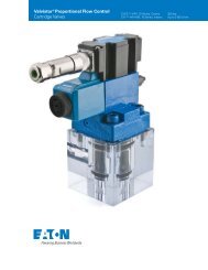
Product Description<br />
The new Series 5 steering control units (SCU) are exciting<br />
new products designed for low flow, low pressure applications.<br />
The Series 5 units are available in two compact designs:<br />
Option 1:<br />
Square Housing (Mount) Unit with Side Ports<br />
Option 2:<br />
Round Housing (Mount) Unit with End Ports<br />
In addition to the installation flexibility provided by the two<br />
options above, this new family of products has best in-class<br />
steering feel and provides crisp centering. These units also<br />
have better efficiency (lower pressure drop) than competitive<br />
units.<br />
Power Beyond Models—Optional power beyond steering<br />
control units supply steering and flow to auxiliary valve functions.<br />
The power beyond unit is used in open center (fixed<br />
displacement pump) systems in the medium pressure range.<br />
When not steering, the power beyond unit directs all inlet<br />
flow to the excess flow port (power beyond) for use in the<br />
auxiliary circuit. Once steering is initiated, and since steering<br />
has priority, inlet flow will be diverted to the steering circuit<br />
as required. Flow out the excess flow port (power beyond)<br />
and tank port will vary or stop depending upon the steering<br />
requirement. The tank port of the steering unit has flow only<br />
when steering is operating.<br />
Features<br />
• Open Center<br />
• Load Sensing<br />
• Open Center<br />
• Power Beyond<br />
Integral Column<br />
• Manual <strong>Steering</strong><br />
Check Valve<br />
• Inlet Relief Valve<br />
• Load Sense Relief Valve<br />
• Cylinder Relief Valve<br />
• Anti-Cavitation Valve<br />
Applications<br />
• Lawn and Garden Equipment<br />
• Turf Equipment<br />
• Golf Course<br />
Maintenance<br />
Equipment<br />
• Lift Trucks<br />
• Compact Utility Tractors<br />
Option 1: Square Housing<br />
with Side Ports<br />
refer to Model Code, page 26<br />
SPECIFICATIONS<br />
Option 2: Round Housing<br />
with End Ports<br />
refer to Model Code, page 27<br />
Max. System Pressure 140 bar [2030 PSI]<br />
Max. Back Pressure 21 bar [ 300 PSI]<br />
Max. Flow 19 l/min [5 GPM]<br />
Max. Differential<br />
Between <strong>Steering</strong> Unit 28° C<br />
and System Temperature 50° F<br />
Max. System Operating<br />
Temperature 93°C [200° F]<br />
Input Torque<br />
Powered -Standard 1,7 - 2,8 Nm @ 6,9 bar tank pressure<br />
[15 - 25 lb-in @ 100 PSI tank pressure]<br />
Low 1,1 - 2,0 Nm @ 6,9 bar tank pressure<br />
[10 - 17.5 lb-in @ 100 PSI tank pressure]<br />
Max. Non Powered 81,4 Nm [60 lb-ft]<br />
Fluid Petroleum Based Fluids<br />
Recommended Filtration ISO 18/13 cleanliness level<br />
Port Options 9/16-18 SAE O-ring<br />
– 06 STC<br />
3/8 BSP Straight thread ports<br />
Check Valve for<br />
Manual <strong>Steering</strong> Yes<br />
Optional Relief Valve 40 [ 580]<br />
Settings bar[PSI] 50 [ 725]<br />
63 [ 914]<br />
70 [1015]<br />
80 [1160]<br />
90 [1305]<br />
100 [1450]<br />
125 [1812]<br />
EATON <strong>Steering</strong> <strong>Catalog</strong> C-STOV-MC001-E2 September 2011 25
<strong>Steering</strong> Control Units—Series 5<br />
Model Code – Ordering Information<br />
Square Housing with Side Ports - Option 1<br />
The following 30-digit coding system has been developed to<br />
identify all of the configuration options for the Series 5 steering<br />
control units. Use this model code to specify a unit with<br />
the desired features. All 30-digits of the code must be present<br />
when ordering. You may want to photocopy the matrix<br />
below to ensure that each number is entered in the correct<br />
box.<br />
Nos Feature Code Description<br />
1,2,3 Product Series ABR Series 5 <strong>Steering</strong> Control Unit<br />
4 Nominal Flow 1 11 l/min [3 GPM]<br />
Rating B 19 l/min [5 GPM]<br />
5 Inlet Pressure<br />
Rating<br />
C 140 bar [2030 PSI]<br />
6 Tank Pressure A 10 bar [150 PSI]<br />
Rating B 21 bar [300 PSI]<br />
7-8 Displacement 35 31.5 cm3 /r [1.92 in3/r]<br />
37 39.5 cm3 /r [2.41 in3/r]<br />
39 50.8 cm3 /r [3.10 in3/r]<br />
41 63.1 cm3 /r [3.85 in3/r]<br />
43 73.8 cm3 /r [4.50 in3/r]<br />
46 100 cm3 /r [6.10 in3/r]<br />
48 120 cm3 /r [7.33 in3/r]<br />
9 Flow Amplification 0 None<br />
10 Neutral Circuit A Open Center<br />
B Open Center, Power Beyond<br />
F Load Sensing, Dynamic signal<br />
11 Load Circuit A Non-Load Reaction<br />
12,13 Valve Options 01 Manual <strong>Steering</strong> Check Valve<br />
04 Inlet Check Valve, Manual<br />
<strong>Steering</strong> Check Valve<br />
05 Inlet Relief Valve,<br />
Manual <strong>Steering</strong> Check Valve<br />
12 Cylinder Relief Valve,<br />
Anti-Cavitation Valve,<br />
Inlet Relief Valve,<br />
Inlet Check Valve,<br />
Manual <strong>Steering</strong> Check Valve.<br />
13 Cylinder Relief Valve,<br />
Anti-cavitation Valve, Inlet Check<br />
Valve, Load Sensing Relief Valve,<br />
Manual <strong>Steering</strong> Check Valve<br />
14,15 Integral Inlet 00 None<br />
Relief Valve 18 40 bar [580 PSI]<br />
Setting 1J 50 bar [725 PSI]<br />
1Z 63 bar [914 PSI]<br />
26 70 bar [1015 PSI]<br />
2G 80 bar [1160 PSI]<br />
2T 90 bar [1305 PSI]<br />
34 100 bar [1450 PSI]<br />
3W 125 bar [1812 PSI]<br />
16,17 Cylinder Relief 00 None<br />
Setting 37 103 bar [1490 PSI]<br />
42 130 bar [1890 PSI]<br />
55 185 bar [2680 PSI]<br />
68 200 bar [2900 PSI]<br />
26<br />
1 2 3 4 5 6 7 8 9 10 11 12 13 14 15 16<br />
17<br />
18<br />
19<br />
20<br />
21<br />
22<br />
23<br />
24<br />
25<br />
26<br />
27<br />
28<br />
29<br />
30<br />
A<br />
B<br />
R<br />
C A<br />
EATON <strong>Steering</strong> <strong>Catalog</strong> C-STOV-MC001-E2 September 2011<br />
0<br />
A<br />
A<br />
0<br />
Nos Feature Code Description<br />
18,19,20, Ports and 4AAN Square 4 x 9/16 SAE Ports,<br />
Mounting Threads M10 x 1,5 Column Mounting<br />
Threads (Use with Open Center)<br />
4AKN Square 5 x 9/16 SAE Ports,<br />
M10 x 1,5 Column Mounting<br />
Threads (Use with Excess Flow)<br />
4AEN Square 5 x 9/16 SAE Ports,<br />
M10 x 1,5 Column Mounting<br />
Threads (Use with Load Sense)<br />
UAAN Square 4 x -06 STC Direct Ports,<br />
M10 x 1,5 Column Mounting<br />
Threads (Use with Open Center)<br />
UBNN Square 5 x -06 STC Direct Ports,<br />
M10 x 1,5 Column Mounting<br />
Threads (Use with Excess Flow)<br />
UBPN Square 5 x -06 STC Direct Ports,<br />
M10 x 1,5 Column Mounting<br />
Threads (Use with Load Sense)<br />
YAAN Square 4 x G .375 BSP Straight<br />
Thd. Ports, M10 x 1,5 Column<br />
Mounting Threads<br />
(Use with Open Center)<br />
YBRN Square 5 x G .375 BSP Striaght<br />
Thd. Ports, M10 x 1,5 Column<br />
Mounting Threads<br />
(Use with Load Sense)<br />
22 Input Torque 1 Low*<br />
3 Standard<br />
23 Fluid Type A See <strong>Eaton</strong> Technical<br />
Bulletin 3-401<br />
24 Special Application 0 None<br />
25,26 Special Feature AA None<br />
27 Paint 1 Black Primer<br />
28 Identification 0 <strong>Eaton</strong> Product Number on<br />
Nameplate<br />
29 Mechanical A Tapered 17.919mm (.7055in)<br />
Interface diameter, .083:1 and serrated<br />
17.5 (.688) diameter, 40 tooth,<br />
M16x1.5-6g, Extension length<br />
65.02 (2.56)<br />
D Internal involute spline12 tooth,<br />
16/32 DP, 30 degree PA<br />
30 <strong>Eaton</strong> Assigned<br />
Design Code<br />
B Assigned Design Code<br />
* All low torque units need approval from an <strong>Eaton</strong> <strong>Steering</strong> Engineer.<br />
1<br />
0<br />
B
<strong>Steering</strong> Control Units—Series 5<br />
Model Code – Ordering Information<br />
Round Housing with End Ports - Option 2<br />
The following 30-digit coding system has been developed to<br />
identify all of the configuration options for the Series 5 steering<br />
control units. Use this model code to specify a unit with<br />
the desired features. All 30-digits of the code must be present<br />
when ordering. You may want to photocopy the matrix<br />
below to ensure that each number is entered in the correct<br />
box.<br />
1 2 3 4 5 6 7 8 9 10 11 12 13 14 15 16<br />
17<br />
18<br />
19<br />
20<br />
21<br />
22<br />
23<br />
24<br />
25<br />
26<br />
27<br />
28<br />
29<br />
30<br />
A B R A<br />
0 A 0 0 A 0 1 0 B<br />
Nos Feature Code Description<br />
1,2,3 Product Series ABR Series 5 <strong>Steering</strong> Control Unit<br />
4 Nominal Flow 1 11 l/min [3 GPM]<br />
Rating B 19 l/min [5 GPM]<br />
5 Inlet Pressure<br />
Rating C 140 bar [2030 PSI]<br />
6 Tank Pressure<br />
Rating<br />
A 10 bar [150 PSI]<br />
7-8 Displacement 35 31.5 cm3 /r [1.92 in3/r]<br />
37 39.5 cm3 /r [2.41 in3/r]<br />
39 50.8 cm3 /r [3.10 in3/r]<br />
41 63.1 cm3 /r [3.85 in3/r]<br />
43 73.8 cm3 /r [4.50 in3/r]<br />
46 100 cm3 /r [6.10 in3/r]<br />
48 120 cm3 /r [7.33 in3/r]<br />
9 Flow Amplification 0 None<br />
10 Neutral Circuit A Open Center<br />
B Open Center, Power Beyond<br />
C Closed Center<br />
F Load Sensing, Dynamic signal<br />
11 Load Circuit A Non-Load Reaction<br />
12,13 Valve Options 01 Manual <strong>Steering</strong> Check Valve<br />
04 Inlet Check Valve, Manual<br />
<strong>Steering</strong> Check Valve<br />
05 Inlet Relief Valve,<br />
Manual <strong>Steering</strong> Check Valve<br />
12 Cylinder Relief Valve,<br />
Anti-cavitation Valve,<br />
Inlet Relief Valve,<br />
Inlet Check Valve,<br />
Manual <strong>Steering</strong> Check Valve.<br />
14,15 Integral Inlet 00 None<br />
Relief Valve 18 40 bar [580 PSI]<br />
Setting 1J 50 bar [725 PSI]<br />
1Z 63 bar [914 PSI]<br />
26 70 bar [1020 PSI]<br />
2G 80 bar [1160 PSI]<br />
2T 90 bar [1310 PSI]<br />
34 100 bar [1450 PSI]<br />
3W 125 bar [1812 PSI]<br />
4C 140 Bar [2030 PSI]<br />
16,17 Cylinder Relief<br />
Setting<br />
00 None<br />
Nos Feature Code Description<br />
18,19, Ports and VAAH Round 4 x 9/16 SAE<br />
20, 21 Mounting Threads Ports, M6 x 1,0 Column<br />
Mounting Threads<br />
(Use with Open Center)<br />
VAKH Round 5 x 9/16 SAE Ports,<br />
M6 x 1,0 Column Mounting<br />
Threads (Use with Excess Flow)<br />
VAEH Round 5 x 9/16 SAE Ports,<br />
M6 x 1,0 Column Mounting<br />
WAAH Round 4 x -06 STC Direct Ports,<br />
M6 x 1,0 Column Mounting<br />
Threads (Use with Open Center)<br />
WBNH Round 5 x -06 STC Direct Ports,<br />
M6 x 1,0 Column Mounting<br />
Threads (Use with Excess Flow)<br />
WBPH Round 5 x -06 STC Direct Ports,<br />
M6 x 1,0 Column Mounting<br />
Threads (Use with Load Sense)<br />
22 Input Torque 1 Low*<br />
3 Standard<br />
23 Fluid Type A See <strong>Eaton</strong> Technical<br />
Bulletin 3-401<br />
24 Special Application 0 None<br />
25,26 Special Feature AA None<br />
27 Paint 1 Black Primer<br />
28 Identification 0 <strong>Eaton</strong> Product Number on<br />
Nameplate<br />
29 Mechanical A Tapered 17.919mm (.7055in)<br />
Interface diameter, .083:1 and serrated<br />
17.5 (.688) diameter, 40 tooth,<br />
M16x1.5-6g, Extension length<br />
65.02 (2.56)<br />
D Internal involute spline12 tooth,<br />
16/32 DP, 30 degree PA<br />
30 <strong>Eaton</strong> Assigned<br />
Design Code<br />
B Assigned Design Code<br />
* All low torque units need approval from an <strong>Eaton</strong> <strong>Steering</strong> Engineer.<br />
** Plug-O ports rated to 103 bar [1500PSI]<br />
EATON <strong>Steering</strong> <strong>Catalog</strong> C-STOV-MC001-E2 September 2011 27
<strong>Steering</strong> Control Units—Series 5<br />
Installation Drawing<br />
Option 1: Square Housing with Side Ports<br />
refer to Model Code, page 26<br />
28<br />
58.37<br />
[2.298]<br />
29,18<br />
[1.149]<br />
Sectional Drawing<br />
4X M10 x 1.5-6H<br />
15,2 [.60] Min<br />
48.26+0.13<br />
[1.900+.005]<br />
Relief Valve/Check Manual Check<br />
Shaft<br />
Seal<br />
38,4<br />
[1.51]MAX<br />
Dust Seal<br />
Bearing<br />
Race<br />
58,37<br />
[2.298]<br />
78,5<br />
[3.09]MAX<br />
44,4 [1.75] Dia.<br />
Involute Spline<br />
12 Tooth 16/32 D.P.<br />
30° P.A. PER SPC DS-023-2<br />
40,6<br />
[1.60] MAX<br />
29,18<br />
[1.149]<br />
58,37<br />
[2.298]<br />
Centering Springs Sleeve Spool Gerotor<br />
Housing Bearing, Ball Pin<br />
Drive O-ring Spacer Plate End Cap<br />
EATON <strong>Steering</strong> <strong>Catalog</strong> C-STOV-MC001-E2 September 2011<br />
Side View<br />
Displacement Dim. A Max.<br />
Code cm 3 /r [in 3 /r] mm [inch]<br />
35 31.5 [1.92] 123.4 [4.86]<br />
37 39.5 [2.41] 125.2 [4.93]<br />
39 50.8 [3.10] 124.2 [4.89]<br />
41 63.1 [3.85] 126.2 [4.97]<br />
43 73.8 [4.50] 128.0 [5.04]<br />
46 100.0 [6.10] 132.3 [5.21]<br />
48 120.0 [7.33] 135.4 [5.33]<br />
Cylinder Relief Valve Anti-Cavitation Valve Inlet Check Valve<br />
Relief Valve/Check<br />
or Manual Check<br />
Gerotor Seal<br />
View of Gerotor Section
<strong>Steering</strong> Control Units—Series 5<br />
Installation Drawing<br />
Option 2: Round Housing with End Ports<br />
Pressure Port<br />
23,6±0,5<br />
[.93±.02]<br />
5X .5625-18<br />
UNF-2B SAE<br />
O-Ring Port<br />
Left Port<br />
22<br />
Involute Spline<br />
12 Tooth 16/32 D.P.<br />
30° P.A.<br />
59,00<br />
[2.323] Dia.<br />
80,5<br />
[3.17] MAX<br />
4 x M6 x 1.0-6H<br />
12,2 [.48] Min. Depth<br />
13,7±0,5<br />
[.54±.02]<br />
Sectional Drawing<br />
21<br />
20,3±0,5<br />
[.80±.02]<br />
19,8±0,5<br />
[.78±.02]<br />
16<br />
VIEW B<br />
44,4<br />
[1.75] MAX<br />
11,4±0,5<br />
[.45±.02]<br />
15<br />
23<br />
69,85±0,05<br />
[2.750±.002] Dia.<br />
80,5<br />
28,6<br />
[3.17] MAX [1.126] MAX Dia.<br />
26,4±0,5<br />
[1.04±.02]<br />
Additional Port<br />
VIEW B<br />
8,9±0,5<br />
[.35±.02]<br />
Right Port<br />
Tank Port<br />
27,9±0,5<br />
14,5±0,5 [1.10±.02]<br />
[.57±.02]<br />
11 10 6 8 3 5<br />
2<br />
D<br />
D<br />
9,1<br />
[.36] MAX<br />
25,7<br />
[1.01] MAX Dia.<br />
C<br />
C<br />
7<br />
9,9<br />
[.39] MIN<br />
5,1±0.8<br />
[.20±.03] 8,9<br />
[.35] MIN<br />
Displacement Dim. A Max.<br />
cm 3 /r [in 3 /r] mm [inch]<br />
31.5 [1.92] 135.1 [5.32]<br />
39.5 [2.41] 137.2 [5.40]<br />
50.8 [3.10] 136.1 [5.36]<br />
63.1 [3.85] 137.9 [5.43]<br />
73.8 [4.50] 139.7 [5.50]<br />
100 [6.10] 144 [5.67]<br />
120 [7.33] 147.3 [5.80]<br />
EATON <strong>Steering</strong> <strong>Catalog</strong> C-STOV-MC001-E2 September 2011 29<br />
A<br />
11 Pin<br />
10 Sleeve<br />
8 Drive<br />
3 O-ring<br />
5 Gerotor<br />
2 End cap<br />
22 Dust seal<br />
16 Bearing<br />
15 Race<br />
21 Quad seal<br />
23 Retaining ring<br />
7 Wear plate<br />
6 housing
<strong>Steering</strong> Control Units—Series 5<br />
Performance Data<br />
Neutral Pressure Drop<br />
Inlet to Auxiliary<br />
30<br />
bar<br />
8<br />
6<br />
4<br />
2<br />
0<br />
0<br />
bar<br />
14<br />
10<br />
6<br />
2<br />
8<br />
[2]<br />
11 L/min [3 GPM] Rated Round Unit<br />
4<br />
[1]<br />
7<br />
[2]<br />
L/min [GPM]<br />
11<br />
[3]<br />
19 L/Min (5 GPM) Rated Unit<br />
11<br />
[3]<br />
15<br />
[4]<br />
L/min [GPM]<br />
19<br />
[5]<br />
[PSI]<br />
[120]<br />
[ 80]<br />
[ 40]<br />
[ 0]<br />
15<br />
[4]<br />
23<br />
[6]<br />
[PSI]<br />
[250]<br />
[200]<br />
[150]<br />
[100]<br />
[ 50]<br />
[ 0]<br />
EATON <strong>Steering</strong> <strong>Catalog</strong> C-STOV-MC001-E2 September 2011<br />
Relief Valve Curve<br />
1 3 5<br />
L/min<br />
7 9 11 13 15<br />
135<br />
2000<br />
1900<br />
125<br />
1800<br />
115<br />
1700<br />
1600<br />
105<br />
1500<br />
95<br />
1400<br />
1300<br />
85<br />
bar<br />
75<br />
1200<br />
PSI<br />
1100<br />
1000<br />
65<br />
900<br />
55<br />
800<br />
45<br />
700<br />
600<br />
35<br />
500<br />
0<br />
0<br />
1 2<br />
GPM<br />
3 4<br />
0<br />
Input Torque Curve<br />
3<br />
Nm 2<br />
1<br />
0 10 20 30 40 50 60 70 80 90 100<br />
Percent Deflection<br />
Standard torque<br />
Low torque<br />
25<br />
20<br />
15<br />
10<br />
in-lb
<strong>Steering</strong> Control Units—Series 5<br />
Integral Column Option<br />
Integral Column Option Available in Square Housing with Side<br />
Ports, and Round Housing with End Ports<br />
40 Tooth Serrated Integral<br />
Column Option (Shown on<br />
Round Housing with End<br />
Ports)<br />
12 Tooth Internal Spline<br />
Standard Mechanical Interface<br />
(Shown on Round Housing<br />
with End Ports)<br />
25.7<br />
[1.01] MAX<br />
69,85±0,05<br />
[2.750±.002] Dia.<br />
M16 x 1.5-6g<br />
Tapered 17.919mm (.7055 in)<br />
dia meter, .083:1 and serr ated<br />
17.5 (.688) d ia meter, 40 tooth,<br />
M16x1.5-6g, Extens ion length<br />
65.02 (2.56)<br />
28,6<br />
[1.126] MAX Dia.<br />
Internal Involute Spline<br />
12 Tooth 16/32 D.P.<br />
30° P.A.<br />
65.0 ± 0.5<br />
[2.56 ± .02]<br />
29.36 ± 0.25<br />
[1.156 ± .010]<br />
14.27 ± 0.25<br />
[.562 ± .010]<br />
17.919<br />
[.7055]<br />
19.2<br />
[.755] MAX<br />
9,1<br />
[.36] MAX<br />
25,7<br />
[1.01] MAX Dia.<br />
9.1<br />
[.36] MAX<br />
.0831:1<br />
9,9<br />
[.39] MIN<br />
5,1±0,8<br />
[.20±.03] 8,9<br />
[.35] MIN<br />
EATON <strong>Steering</strong> <strong>Catalog</strong> C-STOV-MC001-E2 September 2011 31<br />
A
<strong>Steering</strong> Control Units—Series 10<br />
Product Description<br />
<strong>Eaton</strong>’s Series 10 <strong>Steering</strong> Control Unit (SCU) facilitates<br />
hydraulic fluid flow like no other unit on the market. This<br />
highly-engineered product is the ultimate SCU for mid-range<br />
flow applications.<br />
Benefits<br />
• The new Series 10 SCU has an unprecedented, continuous<br />
pressure rating of 275 bar (4000 psi), making it ideal<br />
for heavy-duty equipment, such as construction and<br />
agricultural machinery.<br />
• Its high-pressure rating reduces overall equipment<br />
costs, since smaller cylinder sizes can be assigned into<br />
the system.<br />
• The new Series 10 incorporates proven <strong>Eaton</strong> technologies.<br />
An internal, balanced architecture and a widewalled<br />
sleeve that is 40% thicker than standard designs offer<br />
increased performance during transient pressure conditions.<br />
Features<br />
• Open Center<br />
• Power Beyond<br />
• Closed Center<br />
• Load Sensing<br />
• Integral Valves<br />
• Q-Amp<br />
• 2-Speed<br />
• Dual Displacement<br />
• Versa Steer<br />
• Wide Angle<br />
• Cylinder Damping<br />
Applications<br />
• Construction Machinery<br />
• Agriculture Machinery<br />
• Heavy-Duty Equipment<br />
• Marine<br />
• Forestry Machinery<br />
• Mining Equipment<br />
32<br />
EATON <strong>Steering</strong> <strong>Catalog</strong> C-STOV-MC001-E2 September 2011<br />
SPECIFICATIONS<br />
Max. System Pressure 275 bar [4000 PSI]<br />
Max. Back Pressure<br />
Rated Flow<br />
21 bar [305 PSI]<br />
– Low 7,6 - 15 l/min [ 2 - 4 GPM]<br />
– Medium 15 - 30 l/min [ 4 - 8 GPM]<br />
– High 30 - 61 l/min [ 8 - 16 GPM]<br />
– Low (with Q-Amp) 8 - 19 l/min [ 2 - 5 GPM]<br />
– Medium (with Q-Amp) 19 - 38 l/min [ 5 - 10 GPM]<br />
– High (with Q-Amp)<br />
Max. Differential<br />
Between <strong>Steering</strong> Unit<br />
38 - 76 l/min [10 - 20 GPM]<br />
and System Temperature<br />
Max. System<br />
28° C [50° F]<br />
Operating Temperature<br />
Input Torque<br />
93°C [200° F]<br />
Powered 1,1-2,8 Nm @ 6,9 bar back pressure<br />
[10-25 lb-in @ 100 PSI back pressure]<br />
Non-Powered 136 Nm [100 lb-ft]<br />
Fluid See <strong>Eaton</strong> Technical Bulletin 3-401<br />
Recommended Filtration ISO 18/13 cleanliness level<br />
PORT SIZES:<br />
Work Ports (4) Load Sense (LS) Port (1)*<br />
3/4-16 (SAE) 7/16-20<br />
M18 x 1,5 - 6H M12 x 1,5 - 6H<br />
G 1/2 (BSP) Straight Thread G 1/4 (BSP) Straight Thread<br />
STC Dash 08**<br />
*Top or side when applicable<br />
STC Dash 06**<br />
**STC ® Ports, Aeroquip, feature snap to connect technology
<strong>Steering</strong> Control Units—Series 10<br />
Model Code—Ordering Information<br />
The following 32-digit coding system has been developed to<br />
identify all of the configuration options for the Series 10 steering<br />
control units. Use this model code to specify a unit with<br />
the desired features. All 32-digits of the code must be present<br />
when ordering. You may want to photocopy the matrix<br />
below to ensure that each number is entered in the correct<br />
box.<br />
1 2 3 4 5 6 7 8 9 10 11 12 13 14 15 16 17 18 19 20 21 22 23 24 25 26 27 28 29 30 31 32<br />
A D R A<br />
A A A A A 1 0 A<br />
Nos Feature Code Description<br />
1,2,3 Product Series ADR Series 10 <strong>Steering</strong> Control Unit<br />
4 Unit Type A Standard<br />
B Dual Displacement<br />
C Wide Angle<br />
D 2-Speed<br />
E 2-Speed with Wide Angle<br />
G Dual Displacement with Wide Angle<br />
V Versa Steer, Wide Angle<br />
5 Nominal Flow Rating 1 11 l/min [3 GPM]<br />
(Open Center)<br />
2 23 l/min [6 GPM]<br />
(Closed Center and LS)<br />
3 45 l/min [12 GPM]<br />
(OC, CC, and LS)<br />
4 19 l/min [5 GPM]<br />
(Q-Amp)<br />
5 38 l/min [10 GPM]<br />
(Q-Amp)<br />
6 76 l/min [20 GPM]<br />
(Q-Amp)<br />
7 23 l/min [6 GPM]<br />
(Open Center)<br />
6 Inlet Pressure Rating 1 276 bar [4000 PSI]—(Load<br />
sensing and closed center)<br />
2 207 bar [3000 PSI]—<br />
(Open center)<br />
7 Return Pressure A 21 bar [305 PSI] Max.—<br />
Rating (standard rating*)<br />
B 10 bar [145 PSI] Max.<br />
8-9 Displacement 01 352 [21.5] / 60 [3.6]<br />
cm3 /r [in3 /r] — 02 218 [13.3] / 60 [3.6]<br />
Dual Displacement 03 290 [17.7] / 60 [ 3.6]<br />
Combined/Manual 04 440 [26.8] / 146 [8.9]<br />
05 231 [14.1] / 85 [5.2]<br />
8-9 Displacement 40 60 [3.6]<br />
cm3/r [in3/r] 43 75 [4.5]<br />
45 95 [5.9]<br />
48 120 [7.3]<br />
50 145 [8.9] 1-8 GPM<br />
51 160 [9.7]<br />
52 185 [11.3]<br />
54 230 [14.1]<br />
57 295 [17.9]<br />
59 370 [22.6]<br />
61<br />
64<br />
460 [28.2]<br />
590 [35.9]<br />
8-16 GPM<br />
66 740 [45.1]<br />
Nos Feature Code Description<br />
10 Flow Amplification** A None (No Q-Amp)<br />
B 1.6 : 1.0 Ratio†<br />
C 1.6 : 1.0 Ratio<br />
(with Manual <strong>Steering</strong>)†<br />
E 2.0 : 1.0 Ratio<br />
(with Manual <strong>Steering</strong>)†<br />
G 1.3 : 1.0 Ratio<br />
(with Manual <strong>Steering</strong>)†<br />
†Use with closed center or<br />
load sensing only.<br />
11 Neutral Circuit A Open Center<br />
C Closed Center<br />
D Load Sensing, Static Signal<br />
E Load Sensing, Dynamic Signal<br />
F Open center with<br />
Power Beyond<br />
12 Load Circuit A Non-Load Reaction<br />
B Load Reaction (Open Center<br />
3,8 - 30 l/min [1 - 8 GPM] Only<br />
13,14 Special Spool/Sleeve<br />
Modification<br />
15,16 Valve Options<br />
00 None<br />
Manual Load Inlet Cylinder Anti- Inlet<br />
<strong>Steering</strong> Sensing Check Relief Cavitation Relief<br />
Check Relief Valve Valve Valve Valve<br />
01 •<br />
02 • •<br />
03 • •<br />
04 • • •<br />
05 • •<br />
06 • • •<br />
07 • • •<br />
08 • • • •<br />
09 • • • • •<br />
10 • • • • •<br />
11 • • •<br />
* 12 GPM open center requires 145psi back pressure<br />
** All Q-amp applications need approval from an <strong>Eaton</strong> Applications Engineer<br />
Continued on next page<br />
EATON <strong>Steering</strong> <strong>Catalog</strong> C-STOV-MC001-E2 September 2011 33
<strong>Steering</strong> Control Units—Series 10<br />
Model Code— Ordering Information—Continued<br />
Nos Feature Code Description<br />
17,18 Inlet or Load Sense 00 None<br />
Relief Valve — 18 124 [1800]<br />
bar [PSI] 19 131 [1900]<br />
20 138 [2000]<br />
21 145 [2100]<br />
22 152 [2200]<br />
23 158 [2290]<br />
24 165 [2390]<br />
25 172 [2490]<br />
26 179 [2600]<br />
27 186 [2700]<br />
28 193 [2800]<br />
29 200 [2900]<br />
30 207 [3000]<br />
31 214 [3100]<br />
32 220 [3190]<br />
33 227 [3290]<br />
34 234 [3390]<br />
35 241 [3500]<br />
36 248 [3600]<br />
37 255 [3700]<br />
38 262 [3800]<br />
39 269 [3900]<br />
40 276 [4000]<br />
99 136 [1970]<br />
19,20 Cylinder Relief Valve 00 None<br />
— bar [PSI] 23 158 [2290]<br />
** Cylinder Relief 24 165 [2390]<br />
setting recommen- 25 172 [2490]<br />
dation is 870 PSI 26 179 [2600]<br />
(60 bar) above 27 186 [2700]<br />
steering inlet/load 28 193 [2800]<br />
sense pressure. 29 200 [2900]<br />
30 207 [3000]<br />
31 214 [3100]<br />
32 220 [3190]<br />
33 227 [3290]<br />
34 234 [3390]<br />
35 241 [3500]<br />
36 248 [3600]<br />
37 255 [3700]<br />
38 262 [3800]<br />
39 269 [3900]<br />
40 276 [4000]<br />
41 283 [4100]<br />
42 289 [4190]<br />
43 296 [4290]<br />
44 303 [4390<br />
45 310 [4500]<br />
46 317 [4600]<br />
47 324 [4700]<br />
48 331 [4800]<br />
49 338 [4900]<br />
34<br />
EATON <strong>Steering</strong> <strong>Catalog</strong> C-STOV-MC001-E2 September 2011<br />
Nos Feature Code Description<br />
21,22, Ports and AAAA 4 x 3/4-16 (SAE) Ports<br />
23,24 Mounting None (No Additional Port)<br />
Threads 2 x M12 Mounting Threads<br />
Port Face<br />
4 x M10 Mounting Threads<br />
Mounting Face<br />
AABA 4 x 3/4-16 (SAE) Ports<br />
7/16-20 Load Sensing Port on Side<br />
2 x M12 Mounting Threads<br />
Port Face<br />
4 x M10 Mounting Threads<br />
Mounting Face<br />
AACA 4 x 3/4-16 (SAE) Ports<br />
7/16-20 Load Sensing Port<br />
Face<br />
2 x M12 Mounting Threads<br />
Port Face<br />
4 x M10 Mounting Threads<br />
Mounting Face<br />
BAAA 4 x M18 x 1,5 - 6H Metric<br />
O-ring Ports<br />
None (No Additional Port)<br />
2 x M12 Mounting Threads<br />
Port Face<br />
4 x M10 Mounting Threads<br />
Mounting Face<br />
BADA 4 x M18 x 1,5 - 6H Metric<br />
O-ring Ports<br />
M12 x 1,5 - 6H Load Sensing Port<br />
on Side<br />
2 x M12 Mounting Threads<br />
Port Face<br />
4 x M10 Mounting Threads<br />
Mounting Face<br />
BAEA 4 x M18 x 1,5 - 6H Metric<br />
O-ring Ports<br />
M12 x 1,5 - 6H Load Sensing<br />
Port Face<br />
2 x M12 Mounting Threads<br />
Port Face<br />
4 x M10 Mounting Threads<br />
Mounting Face<br />
CAAA 4 x G 1/2 (BSP) Straight Thread<br />
Ports<br />
None (No Additional Port)<br />
2 x M12 Mounting Threads<br />
Port Face<br />
4 x M10 Mounting Threads<br />
Mounting Face<br />
Continued on next page
<strong>Steering</strong> Control Units—Series 10<br />
Model Code—Ordering Information—Continued<br />
Nos Feature Code Description<br />
21,22, Ports and CAFA 4 x G 1/2 (BSP) Straight Thread<br />
Mounting Ports<br />
Threads G 1/4 (BSP) LS Straight Thread<br />
(continued) Port on Side<br />
2 x M12 Mounting Threads Port<br />
Face<br />
4 x M10 Mounting Threads<br />
Mounting Face<br />
CAGA 4 x G 1/2 (BSP) Straight Thread<br />
Ports<br />
G 1/4 (BSP) LS Straight Thread Port<br />
on Port Face<br />
2 x M12 Mounting Threads Port<br />
Face<br />
4 x M10 Mounting Threads<br />
Mounting Face<br />
DAAA Dash 08 STC® Ports ***<br />
None (No Additional Port)<br />
2 x M10 Mounting Threads Port<br />
Face<br />
4 x M10 Mounting Threads<br />
Mounting Face<br />
DAHA Dash 08 STC® Ports ***<br />
Dash 06 STC® Port on Side<br />
2 x M10 Mounting Threads Port<br />
Face<br />
4 x M10 Mounting Threads<br />
Mounting Face<br />
DAJA Dash 08 STC® Ports ***<br />
Dash 06 STC® Port Face<br />
2 x M10 Mounting Threads Port<br />
Face<br />
4 x M10 Mounting Threads<br />
Mounting Face<br />
25 Mechanical A Internal Involute Spline,<br />
Interface 12 Tooth 16/32 DP 30° PA<br />
26 Input Torque 3 Standard<br />
27 Fluid Type A See <strong>Eaton</strong> Technical<br />
Bulletin 3-401<br />
28,29 Special Features AA None<br />
30 Paints and<br />
Packaging<br />
1 Black Primer<br />
31 Identification 0 <strong>Eaton</strong> Product Number on<br />
Nameplate<br />
32 <strong>Eaton</strong> Assigned<br />
Design Code<br />
B Assigned Design Code<br />
*** STC with inlet check requires threaded adapter. Contact your <strong>Eaton</strong> Account Representative<br />
for assistance.<br />
STC ® —Aeroquip<br />
STC Hose/Connector<br />
Dash 08 Port Face (4)<br />
Dash 06 LS Port Side (1)<br />
STC Port<br />
Patent numbers: 5,553,895<br />
5,226,682<br />
5,570,910<br />
Release Sleeve<br />
Housing<br />
Retaining Ring<br />
Backup Washer<br />
O-ring<br />
EATON <strong>Steering</strong> <strong>Catalog</strong> C-STOV-MC001-E2 September 2011 35
<strong>Steering</strong> Control Units—Series 10<br />
Installation Drawing<br />
PORT AND MOUNTING THREAD COMBINATIONS<br />
Column Load Port<br />
Mounting Sensing* Mounting<br />
Port Thread Port Thread<br />
3/4 -16 M10 x 1,5-6H 7/16 - 20 M12 x 1,75-6H<br />
M18 x 1,5-6H M10 x 1,5-6H M12 x 1,5-6H M12 x 1,75-6H<br />
STC M10 x 1,5-6H STC M12 x 1,75-6H<br />
G 1/2 (BSP) M10 x 1,5-6H G 1/4 (BSP) M12 x 1,75-6H<br />
*Load Sensing Units Only.<br />
36<br />
48,8<br />
[1.92]<br />
Max.<br />
94,0 [3.70] Max.<br />
47,8<br />
[1.88]<br />
45°<br />
56,1[2.21]*<br />
12 Tooth Involute Spline<br />
16/32 D.P. 30° P.A.<br />
14,2 [.56] Deep<br />
Column Mounting<br />
Thread x 15,2 [.60]<br />
Deep on 82,5 [3.25]<br />
Dia. Bolt Circle<br />
Displacement<br />
cm 3 /r Dimension C Dimension D<br />
[in 3 /r] mm [in.] mm [in.]<br />
60 [ 3.6] 10,2 [ .40] 138,1 [5.44]<br />
75 [ 4.5] 10,2 [ .40] 138,1 [5.44]<br />
95 [ 5.9] 13,2 [ .52] 141,1 [5.56]<br />
120 [ 7.3] 16,5 [ .65] 144,4 [5.69]<br />
146 [ 8.9] 20,1 [ .79] 148,0 [5.83]<br />
159 [ 9.7] 21,8 [ .86] 149,9 [5.90]<br />
185 [11.3] 25,4 [1.00] 153,3 [6.04]<br />
231 [14.1] 31,7 [1.25] 159,7 [6.29]<br />
293 [17.9] 40,4 [1.59] 168,3 [6.63]<br />
370 [22.6] 50,8 [2.00] 178,7 [7.04]<br />
462 [28.2] 63,5 [2.50] 191,4 [7.54]<br />
588 [35.9] 80,8 [3.18] 208,8 [8.22]<br />
739 [45.1] 101,6 [4.00] 229,6 [9.04]<br />
EATON <strong>Steering</strong> <strong>Catalog</strong> C-STOV-MC001-E2 September 2011<br />
2,05/3,36 [.081/.132]<br />
37,08/36,32 [1.460/1.430]<br />
63,12/62,62 [2.485/2.465]<br />
56,13/55,37 [2.210/2.180]<br />
Load Sensing Side Port<br />
44,45/44,34<br />
[1.750/1.746]<br />
Dia.<br />
8,2 [.32] Max.<br />
7,4/5,4 [.29/.21] Spline<br />
Left<br />
Right<br />
58,67/58,17<br />
[2.310/2.290]<br />
45,0/44,0<br />
[1.77/1.73]<br />
Max.<br />
94,0<br />
[3.70]<br />
Max.<br />
D<br />
63,25/62,49<br />
[2.490/2.460]<br />
38,61/38,41<br />
[1.52/1.480]<br />
10,2 [.40] Min. Depth (7,1 [.28] Max.<br />
Mating Spline Depth)<br />
103,6<br />
[4.08]<br />
Max.<br />
8,89/8,39<br />
[.350/.330]<br />
Tank Pressure<br />
22,48/21,98<br />
[.885/.865]<br />
Port Mounting Thread x 24,1 [.95] Min. Deep (2)<br />
C<br />
* LS side port<br />
location changes<br />
with a LSR<br />
83,8<br />
[3.30]<br />
Dia. Max.<br />
Load Sensing<br />
Side Port<br />
Load Sensing<br />
Port Face<br />
44,96/43,94<br />
[1.770/1.730]<br />
83,8<br />
[3.30]<br />
Dia.<br />
Max.<br />
60,51/59,49<br />
[2.382/2.342]
<strong>Steering</strong> Control Units—Series 10<br />
Sectional Drawing and Integral Valves<br />
BB<br />
DD<br />
FF<br />
EE<br />
CC<br />
AA<br />
AA<br />
Inlet Check Valve<br />
BB<br />
Inlet<br />
Relief<br />
Valve<br />
CC<br />
Internal<br />
Check<br />
Valve for<br />
Limited<br />
Manual<br />
<strong>Steering</strong><br />
DD<br />
Cylinder Port<br />
EE<br />
Shock Valves<br />
Anti-Cavitation Valves forCylinder Ports<br />
FF<br />
Load<br />
Sense<br />
Relief<br />
Valve<br />
EATON <strong>Steering</strong> <strong>Catalog</strong> C-STOV-MC001-E2 September 2011 37<br />
or
<strong>Steering</strong> Control Units—Series 10<br />
Performance Data<br />
38<br />
Cylinder Relief Valve<br />
Pressure Drop versus Flow<br />
bar<br />
350<br />
280<br />
210<br />
140<br />
Flow l/min<br />
4 6 8 10 12 14 16 18<br />
1 2 3<br />
Flow GPM<br />
4 5<br />
Legend* P1 P2 P3<br />
(23) (27) (30)<br />
[5000]<br />
[4000]<br />
[PSI]<br />
[3000]<br />
[2000]<br />
*The examples above are 4 of 27 pressure settings shown in<br />
model code page 30 Position 19, 20<br />
Anti-Cavitation Valve<br />
Pressure Drop versus Flow<br />
bar<br />
12<br />
10<br />
8<br />
6<br />
4<br />
2<br />
0<br />
EATON <strong>Steering</strong> <strong>Catalog</strong> C-STOV-MC001-E2 September 2011<br />
P4<br />
(34)<br />
Inlet Relief Valve<br />
Pressure Drop versus Flow<br />
220<br />
190<br />
160<br />
bar<br />
130<br />
100<br />
70<br />
Input Torque<br />
0 10<br />
Flow l/min<br />
20 30 40<br />
0 5 10<br />
Flow GPM<br />
Legend**<br />
P1 P2<br />
**The examples above are 2 of 24 pressure settings<br />
shown in model code page 30 Position 17, 18<br />
Flow l/min<br />
0 2 4 6 8 10 12 14 16<br />
[150]<br />
3<br />
32<br />
28<br />
24<br />
[100]<br />
[PSI]<br />
[ 50]<br />
Nm<br />
2<br />
1<br />
20<br />
16<br />
12<br />
8<br />
4<br />
0 1 2 3 4<br />
[ 0]<br />
0<br />
0 10 20 30 40 50 60 70 80 90100 0<br />
Flow GPM<br />
Percent Deflection<br />
Standard Torque<br />
[3000]<br />
[2500]<br />
[PSI]<br />
[2000]<br />
[1500]<br />
[1000]<br />
lb-in
<strong>Steering</strong> Control Units—<br />
Series 10 Dual Displacement<br />
Installation Drawing<br />
48,8<br />
[1.92]<br />
Max.<br />
56,1<br />
[2.21]*<br />
12 Tooth<br />
Involute Spline<br />
16/32 D.P. 30° P.A.<br />
14,2 [.56] Deep<br />
Load Sensing<br />
– Side Port<br />
8,89/8,39<br />
[.350/.330]<br />
94,0 [3.70] Max.<br />
63,25/62,49<br />
[2.490/2.460]<br />
47,8<br />
[1.88]<br />
45°<br />
Powered<br />
Displacement Dimension B Dimension A<br />
cm 3 /r [in 3 /r] mm [in.] mm [in.]<br />
Gerotor 1 and 2<br />
156 [ 9.5] 146,5 [5.77] 182,9 [7.20]<br />
179 [10.9] 146,5 [5.77] 186,2 [7.33]<br />
205 [12.5] 146,5 [5.77] 189,7 [7.47]<br />
218 [13.3] 146,5 [5.77] 191,5 [7.54]<br />
244 [14.9] 146,5 [5.77] 195,1 [7.68]<br />
Column Mounting<br />
Thread x 15,2 [.60]<br />
Deep on 82,5 [3.25]<br />
Dia. Bolt Circle<br />
37,08/36,32 [1.460/1.430]<br />
63,12/62,62 [2.485/2.465]<br />
56,13/55,37 [2.210/2.180]<br />
Load Sensing/Power<br />
Beyond Side Port<br />
Left Right<br />
7,4/5,4 [.29/.21] Spline<br />
44,45/44,34<br />
[1.750/1.746]<br />
Dia.<br />
PORT AND MOUNTING THREAD COMBINATIONS<br />
Column Load Port<br />
Mounting Sensing* Mounting<br />
Port Thread Port Thread<br />
3/4 -16 M10 x 1,5-6H 7/16 - 20 M12 x 1,75-6H<br />
M18 x 1,5-6H M10 x 1,5-6H M12 x 1,5-6H M12 x 1,75-6H<br />
STC** M10 x 1,5-6H STC** M12 x 1,75-6H<br />
G 1/2 (BSP) M10 x 1,5-6H G 1/4 (BSP) M12 x 1,75-6H<br />
*Load Sensing Units Only. **See Page 35 (lower right).<br />
Tank<br />
Manual<br />
Displacement Dimension C<br />
cm 3 /r [in 3 /r] mm [in.]<br />
Gerotor 1<br />
60 [ 3.6] 10,2 [ .40]<br />
60 [ 3.6] 10,2 [ .40]<br />
60 [ 3.6] 10,2 [ .40]<br />
60 [ 3.6] 10,2 [ .40]<br />
60 [ 3.6] 10,2 [ .40]<br />
38,61/38,41<br />
[1.52/1.480]<br />
Pressure<br />
16,3 [.64] 80,3 [3.16]<br />
8,2 [.32] Max.<br />
2,05/3,36<br />
[.081/.132]<br />
25.7°<br />
B<br />
21,1<br />
[.83]<br />
Port Mounting Thread x 24,1 [.95] Min. Deep (2)<br />
10,2 [.40] Min. Depth (7,1 [.28] Max.<br />
Mating Spline Depth)<br />
A<br />
C D<br />
Gerotor 1<br />
Gerotor 2<br />
Load Sensing<br />
Port Face<br />
29,7<br />
[1.17]<br />
22,48/21,98<br />
[.885/.865]<br />
44,96/43,94<br />
[1.770/1.730]<br />
Manual<br />
Displacement Dimension C<br />
cm 3 /r [in 3 /r] mm [in.]<br />
Gerotor 2<br />
95 [ 5.9] 13,2 [ .52]<br />
120 [ 7.3] 16,5 [ .65]<br />
145 [ 8.9] 20,0 [ .79]<br />
160 [ 9.7] 21,8 [ .86]<br />
185 [11.3] 25,4 [1.00]<br />
83,8<br />
[3.30]<br />
Dia.<br />
Max.<br />
60,51/59,49<br />
[2.382/2.342]<br />
EATON <strong>Steering</strong> <strong>Catalog</strong> C-STOV-MC001-E2 September 2011 39
<strong>Steering</strong> Control Units—Series 20<br />
Product Description<br />
The Series 20 steering control unit continues <strong>Eaton</strong>’s tradition<br />
of innovative design and high quality that began with the first<br />
fluid linked power steering system.<br />
You can count on this steering unit to provide the same<br />
smooth, predictable steering as the Char-Lynn steering units<br />
that provide dependable, trouble-free steering on applications<br />
around the world.<br />
• Provides much smoother steering function by minimizing<br />
jerky motion on articulated vehicles.<br />
• Jerk-reducing valves and accumulators can be eliminated<br />
on most vehicles, providing customer savings through<br />
fewer components required and reduced system cost.<br />
• Symmetrical valving provides passageways and valving<br />
that are equally placed, and pressure areas that are<br />
staged for minimum internal leakage. This results in<br />
balance, precise servo response and uniform left or right<br />
steering action.<br />
• <strong>Eaton</strong>’s high capacity gerotor provides ample fluid<br />
displacement from an even more compact unit than was<br />
previously offered.<br />
• A thicker sleeve design provides stability, especially during<br />
pressure and thermal transient conditions.<br />
• The seal and centering spring designs provide positive,<br />
low-effort steering feel to ensure excellent vehicle control,<br />
an important feature for the vehicles for which these<br />
steering control units were designed.<br />
Features<br />
• Load Sensing<br />
• Integral Valves<br />
• Q-Amp<br />
• Wide Angle<br />
• Versa Steer<br />
• Cylinder Damping<br />
Applications<br />
Articulated Vehicles<br />
• Loaders<br />
• Scrapers<br />
• Skidders<br />
• AG Tractors<br />
• Dumpers<br />
• Sprayers<br />
• Forestry Equipment<br />
Rigid Frame Vehicles<br />
• Front End Loaders<br />
• Large Graders<br />
40<br />
EATON <strong>Steering</strong> <strong>Catalog</strong> C-STOV-MC001-E2 September 2011<br />
• Mining Trucks<br />
• Transporters<br />
• AG Tractors<br />
SPECIFICATIONS<br />
Max. System Pressure 241 bar [3500 PSI]<br />
Max. Back Pressure 10 bar [145 PSI]<br />
Rated Flow 95 l/min [25 GPM]<br />
Max. Flow<br />
Max. Differential<br />
125 l/min [33 GPM]<br />
Between <strong>Steering</strong> Unit 28° C<br />
and System Temperature<br />
Max. System<br />
50° F<br />
Operating Temperature<br />
Input Torque<br />
93°C [200° F]<br />
Powered 1,1-2,8 Nm @ 6,9 bar back pressure<br />
[10-25 lb-in @ 100 PSI back pressure]<br />
Non-Powered 136 Nm [100 lb-ft]<br />
Fluid See <strong>Eaton</strong> Technical Bulletin 3-401<br />
Recommended Filtration ISO 18/13 cleanliness level
<strong>Steering</strong> Control Units—Series 20<br />
Model Code – Ordering Information<br />
The following 29-digit coding system has been developed to<br />
identify all of the configuration options for the Series 20 steering<br />
control units. Use this model code to specify a unit with<br />
the desired features. All 29-digits of the code must be present<br />
when ordering. You may want to photocopy the matrix<br />
below to ensure that each number is entered in the correct<br />
box<br />
1 2 3 4 5 6 7 8 9 10 11 12 13 14 15 16 17 18 19 20 21 22 23 24 25 26 27 28 29<br />
A C C 6 A<br />
F N A A A 1 0 C<br />
Nos Feature Code Description<br />
1,2,3 Product Series ACC Series 20 <strong>Steering</strong> Control Unit<br />
4 Nominal Flow 4 38 l/min [10 GPM] (Q-Amp)<br />
Rating 6 76 l/min [20 GPM] (Q-Amp)<br />
7 95 l/min [25 GPM] (Non-Q-Amp)<br />
A 114 l/min [30 GPM] (Q-Amp)<br />
5 Inlet Pressure 6 241 bar<br />
Rating [3500 PSI]<br />
6 Return Pressure<br />
Rating<br />
A 10 bar [145 PSI] Maximum<br />
7-8 Displacement 40 60 [3.6]<br />
cm3/r [in3/r] 43 75 [4.5]<br />
45 95 [5.9]<br />
48 120 [7.3]<br />
50 145 [8.9]<br />
51 160 [9.7]<br />
52 185 [11.3]<br />
54 230 [14.1]<br />
57 295 [17.9]<br />
59 370 [22.6]<br />
61 460 [28.2]<br />
64 590 [35.9]<br />
66 740 [45.1]<br />
69 985 [60.0]<br />
Use with 38<br />
l/min [10 GPM]<br />
Use with 76<br />
l/min [20 GPM]<br />
Use with 114<br />
l/min [30 GPM]<br />
9 Flow Amplification 0 No Q-Amp<br />
1 1.6 : 1.0 Ratio<br />
(Actual Displ. 185 to 985 cm3/r<br />
[11.3 to 60.0 in3/r])<br />
3 2.0 : 1.0 Ratio<br />
(Actual Displ. 60 to 370 cm3/r<br />
[3.6 to 22.6 in3/r])<br />
10 Neutral Circuit F Load Sensing, Dynamic Signal<br />
11 Load Circuit A Non-Load Reaction<br />
D Non-Load Reaction, Cylinder<br />
Damped<br />
Nos Feature Code Description<br />
12,13 Valve Options*<br />
Manual** Load Inlet** Cylinder Anti-<br />
<strong>Steering</strong> Sensing Check Relief Cavitation<br />
Check Relief Valve Valve Valve<br />
00<br />
01 •<br />
02 •<br />
09 • • •<br />
10 • • • •<br />
13 • • • • •<br />
21 • •<br />
24 • • •<br />
40 • • • •<br />
*Not all valve options will work with all unit combinations<br />
**76 l/min [20 GPM] Max.<br />
14,15 Load Sensing Relief 00 None<br />
Valve Setting 4N 150 bar [2180 PSI]<br />
50 160 bar [2320 PSI]<br />
5A 170 bar [2470 PSI]<br />
5L 180 bar [2610 PSI]<br />
5Y 190 bar [2760 PSI]<br />
68 200 bar [2900 PSI]<br />
6J 210 bar [3050 PSI]<br />
6V 220 bar [3190 PSI]<br />
76 230 bar [3340 PSI]<br />
7G 240 bar [3480 PSI]<br />
EATON <strong>Steering</strong> <strong>Catalog</strong> C-STOV-MC001-E2 September 2011 41
<strong>Steering</strong> Control Units—Series 20<br />
Model Code—Ordering Information—Continued<br />
Nos Feature Code Description<br />
16,17 Cylinder 00 None<br />
Relief 6J 210 bar [3050 PSI]<br />
Valve 6V 220 bar [3190 PSI]<br />
Setting 76 230 bar [3340 PSI]<br />
**Cylinder Relief Setting<br />
recommendation is 870<br />
PSI (60 bar) above<br />
steering inlet/load sense<br />
pressure.<br />
42<br />
7G 240 bar [3480 PSI]<br />
7T 250 bar [3630 PSI]<br />
84 260 bar [3770 PSI]<br />
8E 270 bar [3920 PSI]<br />
8R 280 bar [4060 PSI]<br />
92 290 bar [4210 PSI]<br />
9C 300 bar [4350 PSI]<br />
18,19, Ports and AABN 4 x G 1/2 (BSP) Ports with<br />
20,21 Mounting G 1/4 (BSP) Load Sensing Port on<br />
Threads Side, M10 Mounting Threads<br />
DACN 4 x 3/4 (SAE) Ports with 7/16 (SAE)<br />
Load Sensing Port on Side,<br />
M10 Mounting Threads<br />
FAFN 4 x M18 (Metric) Ports with M12<br />
(Metric) Load Sensing Port on Side,<br />
M10 Mounting Threads<br />
FBFN 4 x M18 (Metric) Ports with M14<br />
(Metric) Load Sensing Port on Side,<br />
M10 Mounting Threads<br />
RACN* 4 x 7/8 (SAE) Ports with 7/16 (SAE)<br />
Load Sensing Port on Side,<br />
M10 Mounting Threads<br />
SAFN* 4 x M22 (Metric) Ports with M12<br />
(Metric) Load Sensing Port on Side,<br />
M10 Mounting Threads<br />
SBFN* 4 x M22 (Metric) Ports with M14<br />
(Metric) Load Sensing Port on Side,<br />
M10 Mounting Threads<br />
18,19, Ports and DADN 4 x 3/4 (SAE) Ports with 7/16 (SAE)<br />
20,21 Mounting Load Sensing Port on Port Face,<br />
Threads M10 Mounting Threads<br />
(Load AAWN 4 x G 1/2 (BSP) Ports with G 1/4<br />
Sensing (BSP) Load Sensing Port on Port<br />
Relief Face, M10 Mounting Threads<br />
Only) RADN* 4 x 7/8 (SAE) Ports with 7/16 (SAE)<br />
Load Sensing Port on Port Face,<br />
M10 Mounting Threads<br />
FAVN 4 x M18 (Metric) Ports with M12<br />
(Metric) Load Sensing Port on Port<br />
Face, M10 Mounting Threads<br />
SAVN* 4 x M22 (Metric) Ports with M12<br />
(Metric) Load Sensing Port on Port<br />
Face, M10 Mounting Threads<br />
*Use with 114 l/min [30 GPM]<br />
EATON <strong>Steering</strong> <strong>Catalog</strong> C-STOV-MC001-E2 September 2011<br />
Nos Feature Code Description<br />
22 Input Torque 1 Low<br />
3 Standard (Includes Stiffer Springs)<br />
23 Fluid Type A See <strong>Eaton</strong> Technical Bulletin 3-401<br />
24 Special Application<br />
Options 1 Wide Angle Deflection<br />
V Versa Steer, Wide Angle.<br />
25,26 Special Features AA None<br />
27 Paints and Packaging 1 Black Paint<br />
28 Identification 0 <strong>Eaton</strong> Product Number on<br />
Nameplate<br />
29 <strong>Eaton</strong> Assigned C Assigned Design Code<br />
Design Code
<strong>Steering</strong> Control Units—Series 20<br />
Installation Drawing<br />
See <strong>Catalog</strong> 11-872<br />
for Column Details.<br />
58,37<br />
[2.298]<br />
(2)<br />
29,18<br />
[1.149]<br />
(2)<br />
98,3 [3.87] Max.<br />
M10 x 1,5-6H<br />
16,2 [.60] (4)<br />
44,40 [1.748]<br />
Displ. A B<br />
cm 3 /r [in 3 /r] mm [in.] mm [in.]<br />
60 [ 3.6] 6,1 [ .24] 143,3 [5.64]<br />
75 [ 4.5] 7,9 [ .31] 145,0 [5.71]<br />
95 [ 5.9] 10,2 [ .40] 147,3 [5.80]<br />
120 [ 7.3] 12,7 [ .50] 149,9 [5.90]<br />
145 [ 8.9] 15,5 [ .61] 152,7 [6.01]<br />
160 [ 9.7] 16,8 [ .66] 153,9 [6.06]<br />
185 [11.3] 19,6 [ .77] 156,7 [6.17]<br />
230 [14.1] 24,4 [ .96] 161,5 [6.36]<br />
295 [17.9] 31,0 [1.22] 168,1 [6.62]<br />
370 [22.6] 39,1 [1.54] 176,3 [6.94]<br />
460 [28.2] 48,8 [1.92] 185,9 [7.32]<br />
590 [35.9] 62,2 [2.45] 199,3 [7.85]<br />
740 [45.1] 78,2 [3.08] 215,3 [8.48]<br />
985 [60.0] 103,9 [4.09] 241,0 [9.49]<br />
25,7 [1.01] Max.<br />
12 Tooth Involute Spline<br />
16/32 D.P. 30° P.A.<br />
13,58 [.535] Deep<br />
Mounting<br />
Surface<br />
46,7<br />
[1.84]<br />
26,16<br />
[1.030]<br />
27,69<br />
[1.09]<br />
76,7<br />
[3.02]<br />
48,13<br />
[1.895]<br />
Left<br />
B<br />
9,7 [.38] Min.<br />
4,8 [.19] Min.<br />
8,4 [.33] Max.<br />
3,68/3,43 [.145/.135]<br />
48,51<br />
[1.910]<br />
Tank Pressure<br />
Inlet Check Valve<br />
(with Q-Amp Option)<br />
33,40 [1.315]<br />
A<br />
Load Sensing Port<br />
Right<br />
48,51 [1.910]<br />
E*<br />
19,6 [.77]<br />
90,9<br />
[3.58]<br />
Max.<br />
60,2<br />
[2.37]<br />
63,7<br />
[2.51]<br />
Max.<br />
PORT AND MOUNTING THREAD COMBINATIONS<br />
C D E*<br />
3/4–16 UNF 2B** M10 x 1,5–6H 7/16–20 UNF 2B**<br />
G 1/2*** M10 x 1,5–6H G 1/4***<br />
M18 x 1,5–6H M10 x 1,5–6H M12 x 1,5–6H, M14<br />
M22 x 1,5–6H M10 x 1,5–6H M12 x 1,5–6H, M14<br />
*Load sensing port option—on side (load sense relief<br />
port face only - see page 44).<br />
**SAE O-ring Port Port<br />
***BSP Straight Thread Port<br />
107,4 [4.23] Max.<br />
EATON <strong>Steering</strong> <strong>Catalog</strong> C-STOV-MC001-E2 September 2011 43<br />
D<br />
C
<strong>Steering</strong> Control Units—Series 20<br />
Installation Drawing (Load Sense Relief Option)<br />
44<br />
Load Sense Relief Valve<br />
50,5/49,5<br />
[1.99/1.95]<br />
Left<br />
Tank Pressure<br />
EATON <strong>Steering</strong> <strong>Catalog</strong> C-STOV-MC001-E2 September 2011<br />
Right<br />
Load Sense Port*<br />
• 7/16-20 UNF-2B (SAE) O-ring Port<br />
• G 1/4 (BSP) Straight Thread Port<br />
• M12 x 1,5 -6H (Metric) O-ring Port<br />
*Load sense port on port face (is only available<br />
on units with load sense relief valve).<br />
52,8 [2.08] Max
<strong>Steering</strong> Control Units—Series 20<br />
Sectional Drawing and Integral Valves<br />
Pressure Ports (4)<br />
Anti-Cavitation Valves (2)<br />
Shaft<br />
Seal<br />
(3 piece)<br />
Dust Seal<br />
Bearing<br />
Race<br />
Load<br />
Sensing<br />
Port<br />
Inlet Check<br />
Valve (with<br />
Q-Amp Option)<br />
(Side)<br />
Inlet<br />
Check<br />
Valve<br />
Load Sensing Port*<br />
Load Sense<br />
Relief Valve<br />
*Load Sense Port on Port Face<br />
Available with Load Sense<br />
Relief Option Only<br />
Centering Spring Sleeve Spool Gerotor Cap Screw<br />
Housing Bearing, Needle Pin Ball, Check Drive O-ring Spacer Plate End Cap<br />
Cylinder Relief<br />
Valves (2)<br />
(Standard)<br />
EATON <strong>Steering</strong> <strong>Catalog</strong> C-STOV-MC001-E2 September 2011 45<br />
or<br />
(High Capacity)<br />
View of Gerotor Section
<strong>Steering</strong> Control Units—Series 20<br />
Performance Data<br />
46<br />
Cylinder Relief Valve Pressure<br />
Drop versus Flow<br />
Input Torque<br />
EATON <strong>Steering</strong> <strong>Catalog</strong> C-STOV-MC001-E2 September 2011<br />
bar<br />
350<br />
280<br />
210<br />
140<br />
3<br />
2<br />
Nm<br />
1<br />
0<br />
Flow l/min<br />
4 6 8 10 12 14 16 18<br />
1 2 3<br />
Flow GPM<br />
4 5<br />
Legend P1 P2 P3<br />
(Code) (4Z) (5S) (6J)<br />
0 10 20 30 40 50 60 70 80 90 100<br />
Standard Torque<br />
Low Torque<br />
Percent Deflection<br />
[5000]<br />
[4000]<br />
[3000]<br />
[2000]<br />
P4<br />
(7B)<br />
32<br />
28<br />
24<br />
20<br />
16<br />
12<br />
8<br />
4<br />
0<br />
[PSI]<br />
lb-in
<strong>Steering</strong> Control Units—Series 25<br />
Product Description<br />
The Series 25 SCU includes two designs (Balanced Architecture<br />
and Wide Angle) that make it even more responsive,<br />
reliable and cost effective.<br />
Features<br />
• Open Center<br />
• Closed Center<br />
• Load Sensing<br />
• Integral Valves<br />
• Q-Amp<br />
• Wide Angle<br />
• Pilot Pressure Port<br />
This is an added feature that can be used for:<br />
- Pilot pressure to priority valve<br />
- Diagnostics<br />
• Cylinder Damping<br />
Applications<br />
Articulated Vehicles<br />
• Loaders<br />
• Scrapers<br />
• Skidders<br />
• AG Tractors<br />
Rigid Frame Vehicles<br />
• Large Front End Loaders<br />
• Graders<br />
• Mining Trucks<br />
• Articulated Dump Haulers<br />
• Transporters<br />
Benefits<br />
• Balanced architecture provides passageways that are<br />
equal in both directions and pressure areas that are<br />
staged for minimum leakage. This gives balance, precise<br />
servo response and uniform steering action in both directions<br />
while reducing drift.<br />
• Progressive valving makes it possible to produce the<br />
spool/sleeve valve in a way that assures reliability and<br />
reduces costs.<br />
• <strong>Eaton</strong>’s high capacity gerotor assembly provides a lot of<br />
capacity in a small package.<br />
• Heavier valve components- housing, spool and sleeveprovides<br />
stability, especially during pressure and thermal<br />
transient conditions.<br />
• The seal and centering spring designs provides positive,<br />
low-effort steering feel assuring excellent vehicle control,<br />
an important feature on large vehicles.<br />
SPECIFICATIONS<br />
Max. System Pressure 241 bar [3500 PSI]<br />
Max. Back Pressure 21 bar [300 PSI]<br />
Rated Flow 95 l/min [25 GPM]<br />
Max. Flow<br />
Max. Differential<br />
189 l/min [50 GPM]<br />
Between <strong>Steering</strong> Unit 28° C<br />
and System Temperature 50° F<br />
Max. System<br />
Operating Temperature<br />
Input Torque<br />
93°C [200° F]<br />
Powered 2,8-3,4 Nm @ 6,9 bar back pressure<br />
[25-30 lb-in @ 100 PSI back pressure]<br />
Non Powered †††<br />
Fluid ATF Type A and most petroleum based fluids<br />
Recommended Filtration ISO 18/13 cleanliness level<br />
††† Manual steering is not possible without hydraulic power.<br />
EATON <strong>Steering</strong> <strong>Catalog</strong> C-STOV-MC001-E2 September 2011 47
<strong>Steering</strong> Control Units—Series 25<br />
Model Code – Ordering Information<br />
The following 29-digit coding system has been developed to<br />
identify all of the configuration options for the Series 25 steering<br />
control units. Use this model code to specify a unit with<br />
the desired features. All 29 digits of the code must be present<br />
when ordering. You may want to photocopy the matrix<br />
below to ensure that each number is entered in the correct<br />
box.<br />
Nos Feature Code Description<br />
1,2,3 Product Series ABW Series 25 <strong>Steering</strong> Control Unit<br />
4 Nominal Flow 7 95 l/min [25 GPM]<br />
Rating 8 151 l/min [40 GPM] (Q-amp only)<br />
E 189 l/min [50 GPM] (Q-amp only)<br />
5 Inlet Pressure<br />
Rating<br />
6 241 bar [3500 PSI]<br />
6 Return<br />
Pressure Rating<br />
A 10 bar [150 PSI]<br />
7-8 Displacement 62 490 [30]<br />
cm3/r [in3/r] 65 625 [38]<br />
67 795 [48]<br />
69 985 [60]<br />
71 1230 [75]<br />
9 Flow 0 None<br />
Amplification 1 1.6 : 1.0 Ratio<br />
10 Neutral Circuit A Open Center<br />
C Closed Center<br />
D Closed Center with Neutral Bleed<br />
F Load Sensing, Dynamic Signal<br />
11 Load Circuit A Non-Load Reaction<br />
D Non-Load-Reaction, Cylinder Damping<br />
(Use with Flow Amp and Wide Angle<br />
Only)<br />
12,13 Valve Options 00 None<br />
02 Anti-Cavitation Valve<br />
21 Anti-Cavitation Valve, Cylinder<br />
Relief Valves<br />
14, 15 Load Sense<br />
Relief Valve<br />
Setting<br />
00 None<br />
16,17 Cylinder Relief 00 None<br />
Valve Setting 6F 207 bar [3000 PSI]<br />
**Cylinder Relief Setting 70 224 bar [3250 PSI]<br />
recommendation is 870 7H 241 bar [3500 PSI]<br />
PSI (60 bar) above 83 259 bar [3760 PSI]<br />
steering inlet/load sense 8L 276 bar [4000 PSI]<br />
pressure.<br />
95 293 bar [4250 PSI]<br />
48<br />
1 2 3 4 5 6 7 8 9 10 11 12 13 14 15 16 17 18 19 20 21 22 23 24 25 26 27 28 29<br />
A<br />
B<br />
W<br />
6<br />
A<br />
EATON <strong>Steering</strong> <strong>Catalog</strong> C-STOV-MC001-E2 September 2011<br />
0<br />
0<br />
3 A A A 1 0 D<br />
Nos Feature Code Description<br />
18,19, Ports and EAAA 4 x 1—1/6 Ports<br />
20, 21 Mounting with 3/8-16 UNC Column<br />
Threads Mounting<br />
EAGA 4 x 1—1/6 Ports with 7/16 Load<br />
Sensing Port and 7/16 SAE Pilot<br />
Pressure Port (Capped) with<br />
3/8-16 UNC Column Mounting<br />
(Use with Load Sensing Units<br />
Only)<br />
NBDN 4 x M27 with M12—LS and<br />
M12 PP (Capped) M10 Mounting<br />
Threads (Use with Load Sensing<br />
Units Only)<br />
NAAN 4 x M27 with M10 Mounting<br />
Threads<br />
22 Input<br />
Torque<br />
3 Standard<br />
23 Fluid Type A See <strong>Eaton</strong> Technical Bulletin 3-401<br />
24 Special 0 None<br />
Applications 1 Wide Angle (Use with Load<br />
Sensing Units Only)<br />
25, 26 Special Features AA None<br />
27 Paint 1 Black Paint<br />
28 Identification 0 <strong>Eaton</strong> Product Number on<br />
Nameplate<br />
29 <strong>Eaton</strong> Assigned D Assigned Design Code<br />
Design Code
<strong>Steering</strong> Control Units—Series 25<br />
Installation Drawing<br />
71,4 [2.81]<br />
Max. 4<br />
89,7<br />
[3.53]<br />
Max.<br />
44°/46°<br />
3/8 -16 UNC x<br />
15,2 [.60] Deep<br />
on 82,5 [3.25]<br />
Dia. Bolt Circle<br />
Displacement D Max.<br />
cm 3 /r [in 3 /r] mm [in.]<br />
490 [30] 205,5 [ 8.08]<br />
625 [38] 211,4 [ 8.32]<br />
795 [48] 219,0 [ 8.62]<br />
985 [60] 228,4 [ 8.99]<br />
1230 [75] 239,8 [ 9.44]<br />
89,7 [3.53]<br />
12 Tooth Involute Spline<br />
16/32 D.P. 30° P.A.<br />
15,2 [.60] Min. Deep<br />
108,8<br />
[4.28]<br />
Dia.<br />
Max.<br />
63,5 [2.5]<br />
*Load Sensing Unit Only<br />
31,8<br />
[1.25]<br />
6,3<br />
[.25]*<br />
34°/36°*<br />
Left<br />
44,45/44,43 [1.750/1.746] Dia.<br />
37,4 [1.47]<br />
63,5 [2.5]<br />
138,5<br />
[5.45]<br />
Max.<br />
59,2<br />
[2.33]<br />
Max.*<br />
8,9 [.35] Max.<br />
9,3 [.37] Min. Depth<br />
(7,1 [.28] Max.<br />
Mating Spline Depth)<br />
3,63/1,85 [.143/.073]<br />
Right<br />
8,8 [.35] Min.<br />
Tank<br />
.7,4/5,8<br />
[.29/.19]<br />
Spline<br />
86,1<br />
[3.39]*<br />
95,5 [3.76]*<br />
D<br />
Pressure<br />
1 1/16 UN O-ring Port (4)<br />
Load Sensing*<br />
7/16-20 UNF*<br />
O-ring Port (2)<br />
Plug in PP Port<br />
134,2 [5.28] Max.<br />
25°/27°<br />
5,4 [.21]<br />
73,7<br />
[2.90]<br />
Max.<br />
EATON <strong>Steering</strong> <strong>Catalog</strong> C-STOV-MC001-E2 September 2011 49
<strong>Steering</strong> Control Units—Series 25<br />
Installation Drawing with Cylinder Relief, Anti-Cavitation<br />
50<br />
96,3 [3.79]<br />
Max. (4)<br />
89,7<br />
[3.53]<br />
Max.<br />
108,8<br />
[4.28]<br />
Dia.<br />
Max.<br />
44°/46°<br />
3/8 -16 UNC x<br />
15,2 [.60] Deep<br />
on 82,5 [3.25]<br />
Dia. Bolt Circle<br />
12 Tooth Involute Spline<br />
16/32 D.P. 30° P.A.<br />
15,2 [.60] Min. Deep<br />
63,5 [2.5]<br />
31,8 [1.25]<br />
3,63/1.42 [.143/.096]<br />
6,3<br />
[.25]*<br />
34°/36°*<br />
Left<br />
44,45/44,43 [1.750/1.746] Dia.<br />
37,4 [1.47]<br />
89,7 [3.53]<br />
63,5 [2.50]<br />
*Load Sensing Unit Only<br />
165,9<br />
[6.53]<br />
Max.<br />
59,2<br />
[2.33]<br />
Max.*<br />
8,9 [.35] Max.<br />
9,3 [.37] Min. Depth<br />
(7,1 [.28] Max.<br />
Mating Spline Depth)<br />
EATON <strong>Steering</strong> <strong>Catalog</strong> C-STOV-MC001-E2 September 2011<br />
8,8 [.35] Min.<br />
Tank<br />
.7,4/5,8<br />
[.29/.19]<br />
Spline<br />
86,1<br />
[3.39]*<br />
95,5 [3.76]*<br />
D<br />
Right<br />
Pressure<br />
1 1/16 UN O-ring Port (4)<br />
70,4 [2.77] Max (4)<br />
Load Sensing*<br />
7/16-20 UNF*<br />
O-ring Port (2)<br />
Plug in PP Port<br />
140,0 [5.51] Max.<br />
25°/27°<br />
5,4 [.21]<br />
73,7<br />
[2.90]<br />
Max.<br />
Displacement D Max.<br />
cm3/r [in3/r] Displacement<br />
cm<br />
D Max.<br />
490 [30]<br />
625 [38]<br />
795 [48]<br />
985 [60]<br />
1230 [75]<br />
mm [in.]<br />
205,5 [ 8.08]<br />
211,4 [ 8.32]<br />
219,0 [ 8.62]<br />
228,4 [ 8.99]<br />
239,8 [ 9.44]<br />
3 /r [in3 /r] mm [in.]<br />
490 [30]<br />
625 [38]<br />
795 [48]<br />
985 [60]<br />
1230 [75]<br />
205,5 [ 8.08]<br />
211,4 [ 8.32]<br />
219,0 [ 8.62]<br />
228,4 [ 8.99]<br />
239,8 [ 9.44]
<strong>Steering</strong> Control Units—Series 25<br />
Performance Data<br />
Average Pressure Drop<br />
at Full Valve Deflection<br />
75<br />
60<br />
45<br />
30<br />
bar<br />
15<br />
0<br />
Input<br />
Torque<br />
3<br />
2<br />
Nm<br />
1<br />
0<br />
0 38<br />
[10]<br />
75<br />
[20]<br />
l/min [GPM]<br />
114<br />
[30]<br />
[1000]<br />
[ 800]<br />
[ 600]<br />
[ 400]<br />
[ 200]<br />
[ 0]<br />
151<br />
[40]<br />
0 10 20 30<br />
Low Torque<br />
Wide Angle<br />
40 50 60 70 80<br />
Percent Deflection<br />
90<br />
[32]<br />
[28]<br />
[24]<br />
[20]<br />
[16] [lb-in]<br />
[12]<br />
[ 8]<br />
[ 4]<br />
[ 0]<br />
100<br />
Tank Pressure<br />
[PSI]<br />
Neutral Pressure Drop - Open Center<br />
Fluid Viscosity 25 cSt [120 SUS]<br />
14<br />
[200]<br />
12<br />
10<br />
bar<br />
8<br />
[160]<br />
[120]<br />
[PSI]<br />
6<br />
[ 80]<br />
4<br />
2<br />
[ 40]<br />
0<br />
[ 0]<br />
0 38<br />
[10]<br />
75<br />
[20]<br />
l/min [GPM]<br />
114<br />
[30]<br />
Pressure<br />
Relief<br />
Characteristics<br />
l/min<br />
300<br />
20 40 60 80 100<br />
[4500]<br />
[4000]<br />
250<br />
[3500]<br />
20<br />
15<br />
bar<br />
10<br />
5<br />
0<br />
200<br />
bar<br />
150<br />
100<br />
50<br />
0<br />
[0]<br />
[5] [10] [15] [20] [25]<br />
[GPM]<br />
SCU<br />
Valve<br />
Section<br />
Check<br />
Valve<br />
Characteristics<br />
Left Right<br />
0 20<br />
l/min<br />
40 60<br />
25<br />
[3000]<br />
[2500] [PSI]<br />
[2000]<br />
[1500]<br />
[1000]<br />
[ 500]<br />
80 100<br />
0 5 10 15 20 25<br />
GPM<br />
26.4<br />
EATON <strong>Steering</strong> <strong>Catalog</strong> C-STOV-MC001-E2 September 2011 51<br />
[0]<br />
[360]<br />
[320]<br />
[280]<br />
[240]<br />
[200]<br />
[160]<br />
[120]<br />
[ 80]<br />
[ 40]<br />
[ 0]<br />
[PSI]
<strong>Steering</strong> Control Units—Series 40<br />
Product Description<br />
The Series 40 steering control unit includes two designs that<br />
make it even more responsive, reliable and cost effective.<br />
Benefits<br />
• Symmetrical valving provides passageways and valving<br />
that are equal in both directions and pressure areas that<br />
are staged for minimum leakage. This gives balance, precise<br />
servo response and uniform steering action in both<br />
directions.<br />
• Progressive valving makes it possible to produce the<br />
spool/ sleeve valve in a way that assures reliability and<br />
reduces costs.<br />
• <strong>Eaton</strong>’s high capacity gerotor assembly provides a lot of<br />
capacity in a small package.<br />
• Heavier valve components—housing, spool and sleeve—<br />
provide stability, especially during pressure and thermal<br />
transient conditions.<br />
• The seal and centering spring designs provide positive,<br />
low-effort steering feel assuring excellent vehicle control,<br />
an important feature on large vehicles for which this<br />
steering control was designed.<br />
Features<br />
• Open Center<br />
• Closed Center<br />
• Load Sensing<br />
• Q-amp<br />
• Pilot Pressure Port*<br />
*This is an added feature<br />
that can be used for:<br />
1. pilot pressure to priority valve.<br />
2. diagnostics.<br />
• Cylinder Damping<br />
Applications<br />
Articulated Vehicles<br />
• Loaders<br />
• Scrapers Frame Vehicles<br />
• Large Front End Loaders<br />
• Large Graders<br />
• Mining Trucks<br />
• Articulated Haulers<br />
• Transporters<br />
52<br />
EATON <strong>Steering</strong> <strong>Catalog</strong> C-STOV-MC001-E2 September 2011<br />
SPECIFICATIONS<br />
Max. System Pressure 241 bar [3500 PSI]<br />
Max. Back Pressure 21 bar [300 PSI]<br />
Rated Flow 151 l/min [40 GPM]<br />
Max. Flow<br />
Max. Differential<br />
212 l/min [56 GPM]<br />
Between <strong>Steering</strong> Unit 28° C<br />
and System Temperature<br />
Max. System<br />
50° F<br />
Operating Temperature<br />
Input Torque<br />
93°C [200° F]<br />
Powered 2,8-3,4 Nm @ 6,9 bar back pressure<br />
[25-30 lb-in @ 100 PSI back pressure]<br />
Non Powered †††<br />
Fluid<br />
fluids<br />
ATF Type A and most petroleum based<br />
Recommended Filtration ISO 18/13 cleanliness level<br />
††† Manual steering is not possible without hydraulic power.
<strong>Steering</strong> Control Units—Series 40<br />
Model Code – Ordering Information<br />
The following 29-digit coding system has been developed to<br />
identify all of the configuration options for the Series 40 steering<br />
control units. Use this model code to specify a unit with<br />
the desired features. All 29 digits of the code must be present<br />
when ordering. You may want to photocopy the matrix<br />
below to ensure that each number is entered in the correct<br />
box.<br />
1 2 3 4 5 6 7 8 9 10 11 12 13 14 15 16 17 18 19 20 21 22 23 24 25 26 27 28 29<br />
A B Y 6 B<br />
0 0 0 0 0 0<br />
3 A 0 A A 0 0 C<br />
Nos Feature Code Description<br />
1,2,3 Product Series ABY Series 40 <strong>Steering</strong> Control Unit<br />
4 Nominal Flow 8 151 l/min [40 GPM]<br />
Rating 9 227 l/min [60 GPM] (Q-amp only)<br />
5 Inlet Pressure<br />
Rating<br />
6 241 bar [3500 PSI]<br />
6 Return Pressure<br />
Rating<br />
B 21 bar [300 PSI]<br />
7-8 Displacement 71 1230 [ 75]<br />
cm3/r [in3/r] 74 1560 [ 95]<br />
76 1970 [120]<br />
78 2460 [150]<br />
80 3030 [185]<br />
9 Flow Amplification 0 None<br />
1 1.6 : 1.0 Ratio<br />
10 Neutral Circuit A Open Center<br />
C Closed Center<br />
D Closed Center with Neutral Bleed<br />
F Load Sensing, Dynamic Signal<br />
11 Load Circuit A Non-Load Reaction<br />
E Non-Load Reaction, Cylinder<br />
Damping (Use with Q-amp only)<br />
12,13 Integral Valve 00 None<br />
14,15 Integral Inlet Relief<br />
Valve Pressure<br />
Setting<br />
00 None<br />
16,17 Cylinder Relief<br />
Valve Setting<br />
00 None<br />
Nos Feature Code Description<br />
18,19, Ports and GAAA 4 x 1 – 5/16 SAE Ports with<br />
20, 21 Mounting 3/8-16 UNC Column Mounting<br />
Threads<br />
GAGA 4 x 1 – 5/16 SAE ports with<br />
7/16 SAE Load Sensing Port and<br />
7/16 SAE Pilot Pressure Port with<br />
3/8-16 UNC Column Mounting<br />
Threads (Use with Load Sensing<br />
Only)<br />
22 Input Torque 3 Standard<br />
23 Fluid Type A See <strong>Eaton</strong> Technical Bulletin 3-401<br />
24 Special<br />
Applications<br />
0 None<br />
25,26 Special Features AA None<br />
27 Paint 0 No Paint<br />
28 Identification 0 <strong>Eaton</strong> Product Number on<br />
Nameplate<br />
29 <strong>Eaton</strong> Assigned<br />
Design Code<br />
C Assigned Design Code<br />
EATON <strong>Steering</strong> <strong>Catalog</strong> C-STOV-MC001-E2 September 2011 53
<strong>Steering</strong> Control Units—Series 40<br />
Installation Drawing<br />
54<br />
67,5<br />
[2.66]<br />
1/2 - 13 UNC<br />
x 13,4 [.53]<br />
Deep (3)<br />
Displacement D Max.<br />
cm 3 /r [in 3 /r] mm [in.]<br />
12,9<br />
[.51]<br />
40,7<br />
[1.60]<br />
1230 [ 75] 230,9 [ 9.09]<br />
1555 [ 95] 245,9 [ 9.68]<br />
1965 [120] 265,2 [10.44]<br />
2460 [150] 288,3 [11.35]<br />
3030 [185] 315,0 [12.40]<br />
12 Tooth Involute Spline<br />
16/32 D.P. 30° P.A.<br />
15,2 [.60] Min. Deep<br />
81,3<br />
[3.20]<br />
66,3*<br />
[2.61]<br />
Max.<br />
34°/36°*<br />
1/2 - 13 UNC 13,5 [.53] Deep<br />
on 161,93 [6.375] Dia. Bolt Circle<br />
* Load Sensing Unit Only<br />
44°/46°<br />
6,3*<br />
[.25]<br />
EATON <strong>Steering</strong> <strong>Catalog</strong> C-STOV-MC001-E2 September 2011<br />
127,0/126,4<br />
[5.00/4.98]<br />
Dia.<br />
Left<br />
63,5 [2.5]<br />
31,8 [1.25]<br />
44,45/44,43<br />
[1.750/1.746]<br />
Dia.<br />
3/8 -16 UNC x<br />
15,2 [.60] Deep<br />
on 82,5 [3.25]<br />
Dia. Bolt Circle<br />
27,9 [1.10]<br />
86,1 [3.39]*<br />
63,5 [2.5]<br />
L<br />
T<br />
9,4 [.37] Min. Depth (7,1 [.28] Max.<br />
Mating Spline Depth)<br />
7,4/4,8 [.30/.20] Spline<br />
9,4 [.37] Min.<br />
8,9 [.35] Max.<br />
1,85/3,63 [.073/.143]<br />
Tank<br />
95,5 [3.76]*<br />
PP<br />
LS<br />
D<br />
Right<br />
R<br />
P<br />
Pressure<br />
1 5/16 -12 UN O-ring Port (4)<br />
Load Sensing*<br />
7/16-20 UNF*<br />
O-ring Port (2)<br />
Plug in PP Port<br />
134,2<br />
[5.28]<br />
Max.
<strong>Steering</strong> Control Units—Series 40<br />
Installation Drawing<br />
Average Pressure Drop Through Open Center<br />
Load Sensing and Closed Center at Full Valve Deflection<br />
Open Center Neutral Pressure Drop<br />
Fluid Viscosity 25 cSt [120 SUS]<br />
Input Torque<br />
Applications<br />
• Articulated and Rigid<br />
Dump Trucks<br />
• Mining Trucks<br />
• Paving Equipment<br />
bar<br />
75<br />
60<br />
45<br />
30<br />
15<br />
0<br />
bar<br />
16<br />
14<br />
12<br />
10<br />
8<br />
6<br />
4<br />
2<br />
0<br />
0 38<br />
[20]<br />
0 38<br />
[20]<br />
l/min [GPM]<br />
151<br />
[40]<br />
l/min [GPM]<br />
151<br />
[40]<br />
227<br />
[60]<br />
227<br />
[60]<br />
[PSI]<br />
[1200]<br />
[1000]<br />
[ 800]<br />
[ 600]<br />
[ 400]<br />
[ 200]<br />
[ 0]<br />
[PSI]<br />
[240]<br />
[200]<br />
[160]<br />
[120]<br />
[ 80]<br />
[ 40]<br />
[ 0]<br />
3<br />
32<br />
28<br />
24<br />
20<br />
2<br />
Nm<br />
16<br />
12<br />
lb-in<br />
1<br />
8<br />
4<br />
0<br />
0 10 20 30 40 50 60 70 80 90100 0<br />
Standard Torque Percent Deflection<br />
EATON <strong>Steering</strong> <strong>Catalog</strong> C-STOV-MC001-E2 September 2011 55
Torque Generator<br />
Product Description<br />
Char-Lynn torque generators have been completely redesigned<br />
to meet the needs of the changing marketplace.<br />
These torque generators provide power assist for steering,<br />
eliminating the large hand wheels on gate valves, and provide<br />
powerful rotary motion with effortless manual rotary input on<br />
numerous other applications.<br />
Features<br />
Today’s market includes power steering on electric lift trucks.<br />
Char-Lynn torque generators have been designed with features<br />
that greatly improve the operator’s comfort as well as<br />
the vehicle’s performance. The increase in port surface area<br />
allows for the additional port requirement for units with the<br />
following features:<br />
Power Beyond<br />
This version has three ports: Inlet (IN), Tank (OUT), and Excess<br />
Flow (EF). In the power beyond configuration, flow not<br />
used for priority steering exits the EF port and is available for<br />
the downstream reach function. Flow used for steering will<br />
exit the (OUT) port to tank, and cannot be used for auxiliary<br />
functions.<br />
Load Sensing<br />
Char-Lynn load sensing torque generators use conventional or<br />
load sensing power supplies to achieve load sensing steering.<br />
The use of a load sensing torque<br />
generator and a priority valve in a normal power steering<br />
circuit offers the following advantages:<br />
• Provides smooth pressure compensated steering because<br />
load variations in the steering circuit do not affect<br />
axle response or maximum steering rate.<br />
• Beyond system capability by splitting the system into<br />
two independent circuits. Only the flow required by the<br />
steering maneuver goes to the steering circuit. Flow not<br />
required for steering is available for use in the auxiliary<br />
circuits.<br />
• Because the steering circuit always has flow and pressure<br />
priority.<br />
Char-Lynn load sensing torque generators and priority valves<br />
can be used with open center, closed center or load sensing<br />
systems. Used either in an open center system with a fixed<br />
displacement pump or a closed center system with a pressure<br />
compensated pump, these torque generators offer many<br />
of the features of a load sensing system. Excess flow is available<br />
for auxiliary circuits.<br />
56<br />
EATON <strong>Steering</strong> <strong>Catalog</strong> C-STOV-MC001-E2 September 2011<br />
OUT<br />
AUX<br />
Standard Open Center<br />
Input Torque<br />
Power Beyond<br />
Input Torque<br />
IN<br />
217 Series<br />
(Gerotor Unit)<br />
227 Series<br />
(Geroler Unit)<br />
In<br />
OUT<br />
AUX<br />
Out<br />
In<br />
Out<br />
EF<br />
IN<br />
Gerotor/Geroler<br />
Output Torque<br />
Direct Mechanical Link<br />
Gerotor/Geroler<br />
Torque Generator<br />
Output Torque<br />
Direct Mechanical Link<br />
Torque Generator
Torque Generator<br />
Product Description<br />
Open Center with Case Drain<br />
This high pressure open center torque generator allows the<br />
exit flow from the Torque Generator to operate another function<br />
(for example reach/tilt function of a fork lift vehicle). An<br />
external case drain is needed to protect seals and to allow for<br />
adequate recentering of spool and sleeve. The flow out the<br />
case drain is internal leakage only. This is a series circuit with<br />
some special characteristics that should be noted:<br />
• A relief valve is required in the down stream circuit as<br />
well as a relief valve protecting the torque generator.<br />
• The pressures in this circuit are additive. If it takes 41 bar<br />
[600 PSI] for steering and 55 bar [800 PSI] for the reach<br />
circuit, the pump will see 96 bar [1400 PSI].<br />
• The relief valve for steering must always be set higher<br />
than the relief valve on the downstream function (reach).<br />
The margin between the two must be enough to provide<br />
adequate steering in the worst case (fork lift stationary<br />
and unloaded).<br />
Anti-Friction Needle Bearings<br />
Torque generators are available with anti-friction needle bearings<br />
at the power end to allow for direct mount sprockets or<br />
pinions when compactness of application does not allow for<br />
outboard bearings.<br />
Gerotor or Geroler ® Element<br />
This is a fluid displacement element, consisting of an outer<br />
ring gear and an internal star. Manual low torque input actuates<br />
the spool of the spring centered spool and sleeve valve,<br />
allowing high pressure oil to turn the internal star. This star is<br />
coupled with a splined drive to the output shaft and also the<br />
sleeve of the spool and sleeve valve. High pressure oil turning<br />
the star in this gerotor or Geroler element is generating high<br />
output torque.<br />
The Geroler elements have not been offered on torque<br />
generators in the past. These Gerolers have rolls incorporated<br />
into the outer ring, and the rolls provide rolling contact with<br />
the star point, minimizing friction and improving efficiency.<br />
Limited Manual <strong>Steering</strong><br />
Relative deflection of the input and output shafts is limited<br />
mechanically within the unit so that limited manual steering is<br />
still possible in the event of power loss.<br />
Reaction Torque Resistance<br />
Customer supplied bracket is required for reaction torque<br />
resistance.<br />
Load Sensing<br />
Input Torque<br />
Input Torque<br />
In<br />
Out<br />
LS<br />
Open Center (with Case Drain)<br />
In<br />
Out<br />
Case Drain<br />
Gerotor/Geroler<br />
Direct Mechanical Link<br />
Gerotor/Geroler<br />
Output Torque<br />
Torque Generator<br />
Output Torque<br />
Direct Mechanical Link<br />
Torque Generator<br />
EATON <strong>Steering</strong> <strong>Catalog</strong> C-STOV-MC001-E2 September 2011 57
Torque Generator<br />
Product Information<br />
58<br />
Control End Valve, Sleeve<br />
Shaft, Input/<br />
Valve, Spool<br />
Centering<br />
Springs<br />
Shaft<br />
Seal<br />
Pin<br />
SPECIFICATIONS 217 SERIES—GEROTOR UNIT<br />
Housing, Port/Valve<br />
Drive<br />
Spacer<br />
Plate<br />
Displacement cm3 /r [in3 /r] 76 [4.7] 96 [5.9] 160 [9.7]<br />
Torque Output 62 Nm 79 Nm 124 Nm<br />
(at 70 bar [1000 PSI]) [550 lb-in] [700 lb-in] [1100 lb-in]<br />
Recommended Flow 11,4 l/min 13,2 l/min 13,9 l/min<br />
[3 GPM] [3.5 GPM] [5 GPM]<br />
Max. Operating Speed<br />
(at Rated Pressure and<br />
Recommended Flow)<br />
125 RPM 118 RPM 102 RPM<br />
SPECIFICATIONS 227 SERIES—GEROLER® UNIT<br />
Displacement cm3 /r [in3 /r] 80 [4.9] 102 [6.2] 160 [9.7]<br />
Torque Output 69 Nm 86 Nm 131 Nm<br />
(at 70 bar [1000 PSI]) [608 lb-in] [760 lb-in] [1160 lb-in]<br />
Recommended Flow 11,7 l/min 15,1 l/min 18,9 l/min<br />
[3.1 GPM] [4 GPM] [5 GPM]<br />
Max. Operating Speed<br />
(at Rated Pressure and<br />
Recommended Flow)<br />
125 RPM 118 RPM 102 RPM<br />
EATON <strong>Steering</strong> <strong>Catalog</strong> C-STOV-MC001-E2 September 2011<br />
Spacer<br />
Static<br />
Seals (4)<br />
Gerotor/<br />
Geroler®<br />
Spacer<br />
Plate<br />
Housing,<br />
Power End<br />
(with/Needle<br />
Bearing Option)<br />
Drive<br />
COMMON SPECIFICATIONS 217 AND 227 SERIES<br />
Power End<br />
Shaft,<br />
Output<br />
Quad<br />
Seal<br />
Needle<br />
Bearings<br />
Rated Flow 15,1 l/min [4 GPM]<br />
Max. System<br />
Operating Temperature 93° C [200° F]<br />
Input Torque Powered 1,6 - 2,5 Nm [14 - 22 lb-in]<br />
Non-Powered (Max.) 136 Nm [100 lb-ft]<br />
Output Shaft Side Load at<br />
Keyway Centerline<br />
without Bearing 23 kg [ 50 lb]<br />
with Bearing 272 kg [600 lb]<br />
Fluid Most petroleum hydraulic fluids—see<br />
your <strong>Eaton</strong> representative for use of<br />
fire-resistant and other special fluids<br />
Recommended Filtration As needed to maintain<br />
ISO 18/13 cleanliness level<br />
Rated Pressure Depends on model—See<br />
chart circuit type below<br />
Circuit Type In Port Out Port Aux. Port Max. In minus Out<br />
Open Center 69 bar [1000 PSI] 3 bar [50 PSI] — —<br />
Power Beyond 138 bar [2000 PSI] 3 bar [50 PSI] 138 bar [2000 PSI] 69 bar [1000 PSI]<br />
Load Sensing 69 bar [1000 PSI] 3 bar [ 0 PSI] 69 bar [1000 PSI] —<br />
Open Center w/Case Drain 172 bar [2500 PSI] 103 bar [1500 PSI] 3 bar [50 PSI] 69 bar [1000 PSI]
Torque Generator<br />
Model Code Ordering Information<br />
The following 20-digit coding system has been developed to<br />
identify all of the configuration options for the torque generator.<br />
Use this model code to specify a torque generator with<br />
the desired features. All 20 digits of the code must be present<br />
when ordering. You may want to photocopy the matrix<br />
below to ensure that each number is entered in the correct<br />
box.<br />
Nos Feature Code Description<br />
1,2,3 Product Series ABP Torque Generator<br />
4,5,6 Circuit Type.<br />
and Ratings A4A 15,1 l/min [4 GPM] Open Center<br />
—Max Inlet 69 bar [1000 PSI]<br />
Out 3 bar [50 PSI]<br />
D4C 15,1 l/min [4 GPM] Open Center<br />
Power Beyond<br />
Inlet 138 bar [2000 PSI]<br />
Out 3 bar [50 PSI]<br />
Aux. (PB) 138 bar [2000 PSI] Dp<br />
(Inlet – out)
Torque Generator<br />
Conventional System Circuits<br />
Conventional System with Two Pumps<br />
• Extra cost of two separate circuits<br />
60<br />
Pump<br />
Pump<br />
Torque<br />
Generator<br />
Valve<br />
In<br />
Out<br />
Power Beyond Torque Generator<br />
• Parallel circuit<br />
• <strong>Steering</strong> has priority<br />
• Simple system<br />
• Single relief valve<br />
Cylinder<br />
• Flow to auxiliary function is reduced while steering<br />
EATON <strong>Steering</strong> <strong>Catalog</strong> C-STOV-MC001-E2 September 2011<br />
Conventional System with One Pump<br />
• Can result in insufficient steering flow when operating<br />
the auxiliary function<br />
Relief Valve<br />
Pump<br />
Pump<br />
Torque<br />
Generator<br />
Torque<br />
Generator EF<br />
In<br />
Out<br />
Valve<br />
Valve<br />
In<br />
Out<br />
Cylinder<br />
Cylinder
Torque Generator<br />
Conventional System Circuits<br />
Load Sensing System<br />
• <strong>Steering</strong> has priority<br />
• Auxiliary function can operate at higher pressure than<br />
steering rating; priority valve isolates CF side from EF<br />
side pressures.<br />
• Flow to auxiliary functions reduced while steering<br />
High Back Pressure Torque Generator<br />
• Series circuit; auxiliary and steering pressures are additive<br />
• All flow available to auxiliary function, even while steering<br />
• Separate relief valves required for steering and auxiliary<br />
Pump<br />
Pump<br />
Priority<br />
Valve<br />
Relief Valve<br />
CF<br />
EF<br />
In<br />
Torque LS<br />
Generator Out<br />
In<br />
Case Drain<br />
Torque<br />
Out<br />
Generator<br />
Valve<br />
Valve<br />
Cylinder<br />
Relief Valve<br />
Cylinder<br />
EATON <strong>Steering</strong> <strong>Catalog</strong> C-STOV-MC001-E2 September 2011 61
Torque Generator<br />
Installation Drawing<br />
62<br />
EATON <strong>Steering</strong> <strong>Catalog</strong> C-STOV-MC001-E2 September 2011<br />
Displacement<br />
cm 3 /r [in 3 /r] Dimension mm [inch]<br />
A B C<br />
217 Series 96,1 [5.86] 231,9 [9.13] 114,5 [4.51] 60,4 [2.38]<br />
(Gerotor Unit) 159,6 [9.73] 240,6 [9.47] 123,2 [4.85] 69,3 [2.73]<br />
80,3 [4.90] 233,3 [9.18] 115,9 [4.56] 62,0 [2.44]<br />
227 Series 101,6 [6.20] 237,2 [9.34] 119,8 [4.72] 65,9 [2.59]<br />
(Geroler ® Unit) 160,0 [9.64] 247,5 [9.74] 130,1 [5.12] 76,2 [3.00]
Torque Generator<br />
Ports<br />
For proper operation it is recommended that the unit be<br />
installed so no radial load or thrust load is applied to either<br />
the input or output shafts. Misalignment of shafts will cause<br />
binding.<br />
Displacement<br />
cm 3 /r [in 3 /r] Dimension mm [inch]<br />
C D<br />
217 Series 96,1 [5.86] 60,4 [2.38] 63,5 [2.50]<br />
(Geroler ® Unit) 159,6 [9.73] 69,3 [2.73] 72,1 [2.84]<br />
227 Series 80,3 [4.90] 62,0 [2.44]<br />
(Gerotor Unit) 101,6 [6.20] 65,9 [2.59]<br />
160,0 [9.64] 76,2 [3.00]<br />
EATON <strong>Steering</strong> <strong>Catalog</strong> C-STOV-MC001-E2 September 2011 63
Torque Generator<br />
217 Series Port Block<br />
Installation Drawing Port Block with 3/8-18 Dryseal NPTF Ports<br />
64<br />
EATON <strong>Steering</strong> <strong>Catalog</strong> C-STOV-MC001-E2 September 2011
Torque Generator<br />
227 Series Port Block<br />
Installation Drawing 9/16-18 UNF SAE O-ring Port<br />
Displacement Dim. mm [inch]<br />
cm3 /r [in3 /r] E<br />
80,3 [4.90] 62,0 [2.44]<br />
227 Series 101,6 [6.20] 71,2 [2.80]<br />
(Geroler ® Unit) 160,0 [9.64] 76,2 [3.00]<br />
EATON <strong>Steering</strong> <strong>Catalog</strong> C-STOV-MC001-E2 September 2011 65
Torque Generator<br />
Performance Data<br />
66<br />
Torque Generator<br />
Pressure Drop<br />
EATON <strong>Steering</strong> <strong>Catalog</strong> C-STOV-MC001-E2 September 2011
<strong>Steering</strong> System Components<br />
Antijerk Valves<br />
Description<br />
Antijerk Valves provide smoother steering on articulated vehicles,<br />
such as Wheel Loaders. This is achieved by a pressure<br />
sequence valve mounted on a block. (For more information<br />
see Vickers ® Screw-in Cartridge Valves Cat. V-VLOV-MC001-<br />
E2.)<br />
Features<br />
Dramatically reduces jerk when steering is stopped quickly<br />
and while making aggressive changes in direction. The valve<br />
works by monitoring the margin pressure acting on the<br />
steering valve. Margin spikes when steering wheel speed is<br />
reduced aggressively. When this occurs a small amount of<br />
damping flow is allowed across the turn ports. Unlike accumulators<br />
this valve will not have a negative affect on roading<br />
performance, and it is more cost effective than cushion<br />
valves.<br />
Applications<br />
CF1 is supply from the pump or priority valve, CF2 should<br />
connect to the steering valve UPSTREAM of any check<br />
valves, LS1 & LS2 are the steering valve load-sense connection,<br />
R&L are pass through ports for the turn lines. The<br />
setting of the valve needs to be higher than the normal difference<br />
in pressures between CF and LS, i.e. if CF-LS is 150PSI<br />
then a good setting to start with is 200PSI.<br />
Ordering Information<br />
1. Reference Part Number: 5991006-001<br />
Ports:<br />
CF1, CF2 ¾-16 UNF<br />
L1, L2, R1, R2 ¾-16 UNF<br />
LS1, LS2 7/16-20 UNF<br />
Pressure Setting Range: 100-600PSI<br />
2. Specify Ports.<br />
Ports 8 Size 12 Size<br />
Port Options Option 1 Option 2 Option 3 Option 4<br />
CF1, CF2 ¾-16 UNF M18 1 1/6-12UNF M27<br />
L1, L2, R1, R2 ¾-16 UNF M18 7/8-18 UNF M22<br />
LS1, LS2 7/16-20 UNF M12 7/16-20 UNF M12<br />
3. Choose Pressure Setting Options: Within the 7-40 bar<br />
[100-600 PSI] range with a minimum increment of 3.45<br />
bar [50PSI].<br />
Options: 1 7 bar [100 PSI]<br />
1.5 10.5 bar [150 PSI]<br />
- - - -<br />
6 40 bar [600 PSI]<br />
Electric<br />
Pump M<br />
Emergency<br />
Steer<br />
Pump<br />
Supply<br />
Implement<br />
Valve<br />
EF<br />
P<br />
LS<br />
PFC<br />
Pump<br />
LS<br />
PSV10-10 Pressure Sequence Valves<br />
SPECIFICATIONS<br />
Pressure Rating for<br />
L R<br />
<strong>Steering</strong><br />
Control Unit<br />
LS2 L2 R2<br />
CF1<br />
Anti<br />
Jerk<br />
Valve<br />
Anti<br />
Jerk<br />
Manifold<br />
CF<br />
LS1 L1<br />
Priority<br />
Valve<br />
R1<br />
Aluminum block 210 bar [3000 PSI]<br />
Ductile Iron block 241bar [3500 PSI]<br />
Steer<br />
Cylinders<br />
Temperature Range -40º to 120ºC [-40º to 248ºF]<br />
Fluids All general purpose hydraulic fluids<br />
such as: MIL-H-5606, SAE 10, etc.<br />
Filtration Cleanliness code 18/16/13<br />
EATON <strong>Steering</strong> <strong>Catalog</strong> C-STOV-MC001-E2 September 2011 67
<strong>Steering</strong> System Components<br />
VLC In-Line Priority Valves<br />
60 l/min [16 GPM] Rate Flow<br />
Relief Valve Qualified for<br />
276 bar [4000 psi] max.<br />
Rated CF Pressure is<br />
276 bar [4000 psi]<br />
Rated Inlet and EF Pressure<br />
is 276 bar [4000 psi]<br />
Code System Pressure<br />
Number bar [PSI]<br />
DD 83 [1200]<br />
HE 120 [1725]<br />
LA 138 [2000]<br />
MC 150 [2175]<br />
NC 160 [2300]<br />
QA 172 [2500]<br />
UA 207 [3000]<br />
VD 230 [3325]<br />
VK 240 [3475]<br />
Example: 606-1218-003-QA<br />
68<br />
Product Number<br />
System Pressure<br />
Code Number<br />
The above product number describes a VLC Series with 5,2<br />
bar [75 PSI] control pressure, static signal, 7/8-14 P and EF<br />
ports, 3/4-16 CF port, 7/16-20 LS and T ports, 172 bar [2500<br />
PSI] relief valve setting.<br />
EATON <strong>Steering</strong> <strong>Catalog</strong> C-STOV-MC001-E2 September 2011<br />
Control Pressure - bar [PSI] / Product Number<br />
Static Dynamic Static Dynamic Static Dynamic<br />
Ports (5) Port Size Signal Signal Signal Signal Signal Signal<br />
3,5 [50] 5,2 [75] 5,2 [75] 7,6 [110] 6,9 [100] 10,0 [145]<br />
P & EF 7/8 - 14<br />
CF 3/4 - 16 606-1217 606-1232 606-1218 606-1314 606-1219 606-1315<br />
LS & T 7/16 - 20<br />
P & EF 3/4 -16<br />
CF 9/16 - 18 606-1214 606-1327 606-1215 606-1278 606-1216 606-1328<br />
LS & T 7/16 - 20<br />
P & EF M22 X 1,5<br />
CF M18 X 1,5 606-1329 606-1330 606-1331 606-1333 606-1334<br />
LS & T M12 X 1,5<br />
P & EF R 1/2 - 14<br />
CF R 1/2 - 14 606-1335 606-1336 606-1337 606-1338 606-1339 606-1340<br />
LS & T R 1/4 - 19<br />
For comprehensive information on all steering system components<br />
“Valves” see <strong>Eaton</strong> catalog 11-508.
<strong>Steering</strong> System Components<br />
VLE In-Line Priority Valves<br />
150 l/min [40 GPM]<br />
Rated Flow<br />
Relief Valve Qualified<br />
for 276 bar [4000 PSI]<br />
Max.<br />
Rated CF Pressure is<br />
276 bar [4000 psi]<br />
Rated Inlet and EF<br />
pressure is 303 bar<br />
[4400 psi]<br />
Example: 606-1094-003-QA<br />
Product Number<br />
Code System Pressure<br />
Number bar [PSI]<br />
DD 83 [1200]<br />
HE 120 [1725]<br />
LA 138 [2000]<br />
MC 150 [2175]<br />
NC 160 [2300]<br />
QA 172 [2500]<br />
UA 207 [3000]<br />
VD 230 [3325]<br />
VK 240 [3475]<br />
System Pressure<br />
Code Number<br />
The product number (above left) describes a VLE<br />
Series with 6, 9 bar [100 PSI] control pressure,<br />
static signal, 1 1/16-12 P and EF ports, 3/4-16 CF<br />
port, 7/16-20 LS and T ports, 172 bar [2500 PSI]<br />
relief value setting.<br />
High<br />
Pressure*<br />
For comprehensive information on all steering system components<br />
“Valves” see <strong>Eaton</strong> catalog E-VLFL-MLOO1-E<br />
Control Pressure - bar [PSI] / Product Number<br />
Static Dynamic Static Dynamic Static Dynamic<br />
Ports (5) Port Size Signal Signal Signal Signal Signal Signal<br />
4,5 [65] 5,5 [80] 6,9 [100] 8,6 [125] 10,3 [150] 12,8 [185]<br />
P & EF 1 1/16 -12<br />
CF 3/4 - 16 606-1093 606-1294 606-1094 606-1295 606-1095 606-1296<br />
LS & T 7/16 - 20<br />
P & EF 1 1/16 -12<br />
CF 7/8 - 14 606-1046 606-1341 606-1047 606-1342 606-1048 606-1343<br />
LS & T 7/16 - 20<br />
P & EF 1 5/16 -12<br />
CF 7/8 - 14 606-1058 606-1344 606-1059 606-1345 606-1060 606-1346<br />
LS & T 7/16 - 20<br />
P & EF 1 5/16 - 12<br />
CF 1 5/16 - 12 606-1141 606-1347 606-1142 606-1348 606-1143 606-1349<br />
LS & T 7/16 - 20<br />
P & EF 1 5/16 -12<br />
CF 1 1/16 - 12 606-1350 606-1282 606-1351 606-1281 606-1352 606-1283<br />
LS & T 7/16 - 20<br />
P & EF M27 X 2<br />
CF M18 X 1,5 606-1353 606-1354 606-1355 606-1356 606-1357 606-1358<br />
LS & T M12 X 1,5<br />
P & EF R 3/4 - 14<br />
CF R 1/2 - 14 606-1359 606-1360 606-1361 606-1362 606-1363 606-1364<br />
LS & T R 1/4 - 19<br />
EATON <strong>Steering</strong> <strong>Catalog</strong> C-STOV-MC001-E2 September 2011 69
<strong>Steering</strong> System Components<br />
VLH In-Line Priority Valves<br />
240 l/min [63 GPM] Rated Flow<br />
Code System Pressure<br />
Number bar [PSI]<br />
DD 83 [1200]<br />
HE 120 [1725]<br />
LA 138 [2000]<br />
MC 150 [2175]<br />
NC 160 [2300]<br />
QA 172 [2500]<br />
UA 207 [3000]<br />
VD 230 [3325]<br />
VK 240 [3475]<br />
Rated CF Pressure is<br />
276 bar [4000 psi]<br />
Rated inlet and EF Pressure<br />
is 296 bar [4300 psi]<br />
Example: 606-1202-003-QA<br />
70<br />
Product Number<br />
High<br />
Pressure<br />
System Pressure<br />
Code Number<br />
X = Design Level — NOT part of Order Number.<br />
The product number (above left) describes a VLH<br />
Series with 6, 9 bar [100 PSI] control pressure,<br />
static signal, 1 5/8-12 P and EF ports, 1 5/16-12 CF<br />
port, 7/16-20 LS and R ports, 172 bar [2500 PSI]<br />
relief value setting.<br />
For comprehensive information on all steering<br />
system components “Valves” see <strong>Eaton</strong> catalog<br />
11-508.<br />
EATON <strong>Steering</strong> <strong>Catalog</strong> C-STOV-MC001-E2 September 2011<br />
Control Pressure - bar [PSI] / Product Number<br />
Static Dynamic Static Dynamic Static Dynamic<br />
Ports (5) O-ring Signal Signal Signal Signal Signal Signal<br />
Port Size 5,2 [75] 5,9 [85] 6,9 [100] 7,6 [110] 10,3 [150] 11,4 [165]<br />
P & EF 1 5/8 - 12<br />
CF 1 5/16 - 12 606-1201 606-1288 606-1202 606-1289 606-1203 606-1290<br />
LS & R 7/16 - 20<br />
P & EF 1 5/8 - 12<br />
CF 1 1/16 - 12 606-1368 606-1284 606-1369 606-1285 606-1370 606-1286<br />
LS & R 7/16 - 20<br />
P & EF 1 5/8 - 12<br />
CF 3/4 - 16 606-1189 606-1371 606-1190 606-1372 606-1191 606-1373<br />
LS & R 7/16 - 20
<strong>Steering</strong> System Components<br />
VLC, VLE and VLH Priority Valves – Pressure Drop Curves<br />
VLC Series<br />
VLE Series<br />
VLH Series<br />
Symbols<br />
For comprehensive information on all steering<br />
system components “Valves” see <strong>Eaton</strong> catalog<br />
E-VLFL-MLOO1-E<br />
EATON <strong>Steering</strong> <strong>Catalog</strong> C-STOV-MC001-E2 September 2011 71
<strong>Steering</strong> System Components<br />
Check Valves Product Description<br />
These check valves are designed specifically to withstand the<br />
rugged duty cycles of a steering system and perform their<br />
functions reliably to prevent kickback in the steering wheel.<br />
The check valve is installed directly into the pressure port of<br />
Char-Lynn steering control unit. Connection of the hose assembly<br />
is either a male 37° end or O-ring face seal (ORS).<br />
Straight 90° elbow configurations are available (see installation<br />
drawing next page).<br />
Performance Data<br />
Pressure Drop Curves — Inlet Check Valves<br />
72<br />
EATON <strong>Steering</strong> <strong>Catalog</strong> C-STOV-MC001-E2 September 2011
<strong>Steering</strong> System Components<br />
Check Valves Installation Drawing<br />
C<br />
Hex.<br />
Product<br />
Configuration Number Check Valve Dimensions—mm [in.]<br />
A<br />
D<br />
B<br />
E<br />
Straight<br />
A B C D E<br />
37° 608-1003 3/4-16 3/4-16 22,61/22,10 [.89/.87] 43.69/43.18 [1.72/1.70] 14.48/13.46 [.57/.53]<br />
37° 608-1004 9/16-18 3/4-16 22,61/22,10 [.89/.87] 41.15/40.64 [1.62/1.60] 14.48/13.46 [.57/.53]<br />
Straight ORS 608-1007 13/16-16 3/4-16 22,61/21,10 [.89/.87] 39.88/39.37 [1.57/1.55] 14.48/13.46 [.57/.53]<br />
ORS 608-1009 11/16-16 3/4-16 22,61/22,10 [.89/.87] 38.16/37.59 [1.50/1.48] 14.48/13.46 [.57/.53]<br />
90° ORS 608-1013 11/16-18 3/4-16 24,13/23,62 [.95/.93] 37,6/35,5 [1.48/1.40] 41.15/40.13 [1.62/1.58]<br />
C<br />
Hex.<br />
C<br />
Hex.<br />
O-ring<br />
Face Seal<br />
(ORS)<br />
90° Elbow<br />
E<br />
D<br />
A B<br />
D<br />
E<br />
B<br />
A<br />
EATON <strong>Steering</strong> <strong>Catalog</strong> C-STOV-MC001-E2 September 2011 73
<strong>Steering</strong> System Components<br />
Relief Valves<br />
Model 32107 In-Line Relief Valve–Direct<br />
Acting Cartridge<br />
Specifications<br />
Max. Flow Through<br />
Relief Valve 57 l/min<br />
[15 GPM]<br />
Relief Valve<br />
Setting Range 47–276 bar<br />
[675–4000 PSI]<br />
Standard Relief<br />
Valve Setting 138 bar [2000 PSI]<br />
Housing Rated<br />
Pressure 345 bar [5000 PSI]<br />
Model 32107 In-Line Relief Valve–Pilot<br />
Operated Cartridge<br />
Specifications<br />
Max. Flow Through<br />
Relief Valve 75,7 l/min<br />
[20 GPM]<br />
Relief Valve<br />
Setting Range 103–241 bar<br />
[1500–3500 PSI]<br />
Housing Rated<br />
Pressure 345 bar [5000 PSI]<br />
Model 32112 In-Line Relief Valve<br />
Specifications<br />
Max. Flow Through<br />
Relief Valve 132,5 l/min<br />
[35 GPM]<br />
Relief Valve<br />
Setting Range 69–241 bar<br />
[1000–3500 PSI]<br />
Housing Rated<br />
Pressure 345 bar [5000 PSI]<br />
Comprehensive Relief Valve Description<br />
(see <strong>Eaton</strong> Relief Valve <strong>Catalog</strong> 11-510)<br />
74<br />
EATON <strong>Steering</strong> <strong>Catalog</strong> C-STOV-MC001-E2 September 2011<br />
T<br />
T<br />
P<br />
P<br />
P<br />
P<br />
P P<br />
T
<strong>Steering</strong> System Components<br />
Columns Product Description<br />
Char-Lynn columns can be custom built to your exact specifications.<br />
The column and mounting flange is of a sturdy single<br />
weldment design. These columns have high thrust and side<br />
load capacity with low shaft tortional friction. Columns are<br />
painted with low gloss black finish and the shafts are phosphate<br />
coated and oil dipped for corrosion protection.<br />
Features<br />
• Low friction bearings to carry thrust and side loads<br />
• dust boot to protect against dirt and moisture<br />
• Four jacket types are available<br />
• Two lower ends and ten upper ends are available<br />
• Two different horn wire configurations<br />
• Available from 56 to 825 mm [2.2 to 32.5 inch]<br />
• Pre-assembled to steering units per your request<br />
SPECIFICATIONS<br />
Rated Tortional 81Nm [60 lb-ft]<br />
Rated Bending Moment* 136 Nm [100 lb-ft]<br />
Rated Radial Load** 86 kg [150 lb]<br />
Rated Axial Load 86 kg [150 lb]<br />
Tortional Friction Drag 0,23 kg [2 lb-in]<br />
Recommended Wheel Nut Torque 47 Nm [35 lb-ft]<br />
*Bending moments are taken about the plane of the column mounting surface.<br />
**Radial load at the bearing centerline must not exceed the horizontal bending moment rating.<br />
Five Steps for “How to Order Your Column”<br />
1. Select Jacket/Base Type<br />
2. Select Lower Shaft Type<br />
3. Select Upper Shaft End Type<br />
4. Select Length (use suggested standard length)<br />
5. Select Add-On Features<br />
a) Horn Wire<br />
b) Wire Ends<br />
• Please contact your <strong>Eaton</strong> Representative if any request<br />
differs from our catalog offerings.<br />
Shaft End<br />
C L of Bearing<br />
Mounting Flange Surface<br />
d<br />
EATON <strong>Steering</strong> <strong>Catalog</strong> C-STOV-MC001-E2 September 2011 75<br />
L<br />
Use non-soap base grease<br />
for column, spline, steering<br />
unit interface<br />
P a<br />
T
<strong>Steering</strong> System Components<br />
Columns Model Code, Ordering Information<br />
The following 22-digit coding system has been developed to<br />
identify all of the configuration options for steering columns.<br />
Use this model code to specify a steering column with the<br />
desired features. All 22 digits of the code must be present<br />
when ordering. You may want to photocopy the matrix below<br />
to ensure that each number is entered in the correct box.<br />
BOLT & NUT KITS<br />
Metric Cap Screw Kit M10 x 1.5 Thread x 20mm Length (Qty 4) 9900157-000<br />
Standard Cap Screw Kit .375-16 UNC Thread x .75” Length (Qty 4) 9900158-000<br />
Metric Jam Nut Kit M18 x 1.5 (Qty 1) 9900159-000<br />
Hex Nut Kit 13/16-20 NEF (Qty 1) 9900160-000<br />
Hex Nut Kit 1 1/2 - 12 UNF (Qty 1) 9900161-000<br />
Separate kits are available for purchase to use with steering columns<br />
76<br />
1 2 3 4 5 6 7 8 9 10 11 12 13 14 15 16 17 18 19 20 21 22<br />
A<br />
Nos Feature Code Description<br />
C<br />
K<br />
1,2,3 Product Series ACK <strong>Steering</strong> Column<br />
4,5 Jacket/Base Type SJ Standard (38 mm [1.50 inch] O.D.)<br />
(page MN Round Series 5 (38mm [1.5 inch] O.D.)<br />
74) HG Heavy Wall (41,4 [1.63 inch] O.D.)<br />
Tabbed Flange<br />
SH Standard With flat Flange<br />
(38mm [1.50 inch] O.D.) (No Tabs)<br />
TJ Tilt Column with Flat Flange,<br />
Mechanical Push Button<br />
6 Lower Shaft End 1 12 Tooth Spline for <strong>Steering</strong> Unit<br />
(see page 3 3/4 inch “D” Section<br />
75) (for Noise Isolator)<br />
7,8 Upper Shaft End AJ Standard for all rigid and tilt columns<br />
(see illustrations Available with or without Horn Wire<br />
and specifications MJ Available with or without Horn Wire<br />
page DN Not Available with Horn Wire<br />
76, 77) EJ Not Available with Horn Wire<br />
GC Not Available with Horn Wire<br />
CL Not Available with Horn Wire<br />
PT Available with or without Horn Wire<br />
SV Available with or without Horn Wire<br />
9,10,11 Jacket Length<br />
YM Not Available with Horn Wire<br />
022 56,6 [ 2.23]<br />
mm [in.] 033 82,8 [ 3.26]<br />
(Suggested Std. 058 147,8 [ 5.82]<br />
Dim.) 078 197,1 [ 7.76]<br />
099 250,7 [ 9.87]<br />
108 273,3 [10.76]<br />
118 298,7 [11.76]<br />
157 399,8 [15.74]<br />
178 451,6 [17.78]<br />
253 642,1 [25.28]<br />
273 692,4 [27.26]<br />
298 756,4 [29.78]<br />
325 826,3 [32.53]<br />
060 152,4 [ 6.00]<br />
080 203,2 [ 8.00]<br />
100 254,0 [10.00]<br />
120 304,8 [12.00]<br />
EATON <strong>Steering</strong> <strong>Catalog</strong> C-STOV-MC001-E2 September 2011<br />
Nos Feature Code Description<br />
0<br />
140 355,6 [14.00]<br />
160 406,4 [16.00]<br />
026 66,1 [ 2.60]<br />
036 92,3 [ 3.63]<br />
062 157,3 [ 6.19]<br />
081 206,6 [ 8.13]<br />
103 260,2 [10.24]<br />
111 282,8 [11.13<br />
121 308,2 [12.13]<br />
162 409,3 [16.11]<br />
182 461,1 [18.15]<br />
257 651,6 [25.65]<br />
276 701,9 [27.63]<br />
302 765,9 [30.15]<br />
329 835,7 [32.90]<br />
AAA 190,5 [ 7.50] Above Pivot<br />
546,4 [21.51] Below Pivot<br />
AAB 190,5 [ 7.50] Above Pivot<br />
101,6 [ 4.00] Below Pivot<br />
AAC 127,0 [ 5.00] Above Pivot<br />
127,0 [ 5.00] Below Pivot<br />
12-16 Horn Wire Feature 00000 No Horn Wire<br />
(page 79) 1A045 Single Horn Wire<br />
2B045 Two Horn Wires<br />
17 Horn Brush Wire 0 None—Select When No<br />
Terminal End Horn Wire Used<br />
(page 79) D SAE J928 Pin and<br />
Double End Connector<br />
K Blade Receptacle—Insulated<br />
(Compatible with SAE J858a)<br />
18,19 Shaft End Wire 00 None<br />
Terminal 01 One Horn Button<br />
(page 79) (Only with One Horn Wire)<br />
02 One Horn Button with Wire Eyelet<br />
(Select with Two horn Wire)<br />
08 Tinned Bare Wire End<br />
20,21 Special Feature 00 None<br />
22 <strong>Eaton</strong> Assigned<br />
Design Code B For Tilt columns<br />
0<br />
Tilt Column
<strong>Steering</strong> System Components<br />
Columns Jacket/Base Type<br />
*Dimension X—see model code page 73 Position 9, 10, 11 (Jacket Length)<br />
SJ Standard Wall<br />
(Available on Square Series 5, Series 10, 20, 25, 40)<br />
Position 4-5<br />
40,6<br />
[1.6]<br />
Dia.<br />
Shaft End<br />
Position 4-5<br />
40,6<br />
[1.6]<br />
Dia.<br />
Shaft End<br />
Dimension X*<br />
15,2 [.60]<br />
44,32 20,3 [.80]<br />
[1.745]<br />
Pilot Dia.<br />
41,4<br />
[1.63]<br />
Dia.<br />
Mounting<br />
Surface<br />
Tab (4)<br />
Dimension X*<br />
23,6 [.93]<br />
44<br />
[1.73] 5,77 [.227]<br />
Pilot Dia.<br />
38<br />
[1.49]<br />
Dia.<br />
Mounting<br />
Surface<br />
6,4 [.25]<br />
HG Heavy Wall<br />
(Available on Square Series 5, Series 10, 20, 25, 40)<br />
6,4 [.25]<br />
9,4 [.37]<br />
Example—see model code page 76<br />
Position Example—see 4-5 model code page 73<br />
SH Position 4-5 Standard with flat flange (No Tabs)<br />
SH Standard with flat flange (No Tabs)<br />
Position 9, 10, 11<br />
Position 9, 10, 11<br />
026 66,1 [2.60] [2.60] (Dimension (Dimension X) X)<br />
SH Standard Wall<br />
(Available on Square Series 5, Series 10, 20, 25, 40)<br />
Position 4-5<br />
Position 4-5<br />
40,6<br />
[1.6]<br />
Dia.<br />
40,6<br />
[1.6]<br />
Dia.<br />
Shaft End<br />
Shaft End<br />
Dimension X*<br />
23,6 [.93]<br />
44,32 5,77 [.227]<br />
[1.745]<br />
Pilot Dia.<br />
Dimension X*<br />
23,6 [.93]<br />
44<br />
[1.73] 5,77 [.227]<br />
Pilot Dia.<br />
38<br />
[1.49]<br />
Dia.<br />
38,1<br />
[1.5]<br />
Dia.<br />
Mounting<br />
Surface<br />
Mounting<br />
Surface<br />
MN<br />
(Round Series 5 with End Ports Only)<br />
6,4 [.25]<br />
6,4 [.25]<br />
9,4 [.37]<br />
EATON <strong>Steering</strong> <strong>Catalog</strong> C-STOV-MC001-E2 September 2011 77
<strong>Steering</strong> System Components<br />
Columns Lower End Type<br />
1<br />
3<br />
78<br />
6,4 [.25]<br />
Position 6 Column Mounting<br />
Column Mounting<br />
Flange with Tabs<br />
Flange without Tabs<br />
18,8 [.74] Min.<br />
107,8/105,6<br />
[4.24/4.16]<br />
EATON <strong>Steering</strong> <strong>Catalog</strong> C-STOV-MC001-E2 September 2011<br />
12 Tooth Spline to Fit Char-Lynn ® <strong>Steering</strong> Control Units<br />
Position 6 3/4 inch “D” Section<br />
(for Noise Isolator)<br />
Noise Isolator (Not Icluded)<br />
13,54/13,44<br />
[.533/.529]<br />
Example—see model code page 73<br />
Position Example—see 6 model code page 76<br />
1 12 Tooth Spline for <strong>Steering</strong> Unit<br />
Position 6<br />
1 12 Tooth Spline for <strong>Steering</strong> Unit<br />
6,1 [.24]<br />
Column Mounting<br />
Flange for Round Series 5<br />
with Side or End Ports<br />
Upper Shaft End EJ (Ref.)
<strong>Steering</strong> System Components<br />
Columns Upper Shaft End<br />
AJ<br />
Position 7-8<br />
Not Available<br />
with Horn<br />
Wire<br />
32,3 [1.31]<br />
16,0 [.63]<br />
Note: Torque Nut to<br />
41-54 Nm [30-40 lb-ft]<br />
26,4 [1.04]<br />
12,7 [.50]<br />
Note: Torque Nut to<br />
41-54 Nm [30-40 lb-ft]<br />
For bending moment<br />
calculation when using<br />
<strong>Eaton</strong> wheel product<br />
No. 209-1007, wheel rim<br />
is 22,1 [.87] above threaded<br />
end steering shaft.<br />
MJ<br />
Position 7-8<br />
Note: Torque Nut to<br />
41-54 Nm [30-40 lb-ft]<br />
For bending moment<br />
calculation when using<br />
<strong>Eaton</strong> wheel product<br />
No. 209-1007, wheel rim<br />
is 22,1 [.87] above threaded<br />
end steering shaft.<br />
DN<br />
Position 7-8<br />
26,4 [1.04]<br />
12,7 [.50]<br />
45,34<br />
[1.785]<br />
.052 : 1<br />
36 Tooth Straight Serration<br />
21,79 [.858] Major Dia.<br />
13/16 - 20 UNF - 2A Thread<br />
45,34<br />
[1.785]<br />
57,15<br />
[2.250]<br />
22,22 x 4,775<br />
[.870 x .1880]<br />
Wide Key<br />
20,10 [.790] Dia.<br />
.0625 : 1<br />
3/4 -16 UNF-2A Thread<br />
21,82 [.859] Dia.<br />
21,82 [.859] Dia.<br />
.052 : 1<br />
36 Tooth Straight Serration<br />
21,79 [.858] Major Dia.<br />
M20 x 1,5 - 6g Thread<br />
Example—see model code page 76<br />
Example—see model code page 73<br />
Position 7-8<br />
Position 7-8<br />
EJ (36 Tooth Straight Straight Serration) Serration)<br />
Not available with with horn wire<br />
EJ<br />
Position 7-8<br />
GC<br />
Position 7-8<br />
16,26 [.640]<br />
Not Available<br />
with Horn<br />
Wire<br />
21,8 [.86]<br />
15,2 [.60]<br />
45,34<br />
[1.785]<br />
36 Tooth Straight Serration<br />
18,59 [.732] Major Dia.<br />
22,17 [.873] Dia.<br />
10,9 [.43]<br />
R 1,6 [.06]<br />
Max.<br />
30,99 [1.220]<br />
9,48 [.373]<br />
Dia.<br />
Crosshole<br />
EATON <strong>Steering</strong> <strong>Catalog</strong> C-STOV-MC001-E2 September 2011 79
<strong>Steering</strong> System Components<br />
Columns Upper Shaft End Continued<br />
80<br />
CL<br />
Position 7-8<br />
Not Available<br />
with Horn 45,50 [1.790]<br />
Wire<br />
29,36 [1.156]<br />
14,27 [ .562]<br />
Note: Torque Nut to<br />
41-54 Nm [30-40 lb-ft]<br />
50,5 [1.99]<br />
M16 x 1,5 - 6g Thread<br />
40 Tooth Straight Tooth Serration<br />
17,48 [.688] Major Dia. .083 : 1<br />
PT<br />
Position 7-8<br />
30,00 [1.181]<br />
15,00 [.590]<br />
Note: Torque Nut to<br />
41-54 Nm [30-40 lb-ft]<br />
M18 x 1,5 - 6g Thread<br />
36 Tooth Straight Serration<br />
20,55 [.809] Major Dia.<br />
55,00 [2.165]<br />
17,92 [.705] Dia.<br />
21,00 [.827] Dia.<br />
.0625 : 1<br />
EATON <strong>Steering</strong> <strong>Catalog</strong> C-STOV-MC001-E2 September 2011<br />
Example—see model code page 76<br />
Position<br />
Example—see<br />
7-8<br />
model code page 73<br />
YM Position 7-8 (.050 : 1 Taper M18 x 1,5 - 6g Thread)<br />
YM (.050 : 1 Taper M18 x 1,5 - 6g Thread)<br />
Not available with horn wire<br />
Not available with horn wire<br />
YM<br />
Position 7-8<br />
Not Available<br />
with Horn<br />
Wire or Tilt 32,0 [1.26]<br />
M18 x 1,5 - 6g Thread<br />
26,9 [1.06]<br />
M18 x 1,5 - 6H<br />
Thread Jam Nut<br />
8,9 [.35]<br />
Note: Torque Nut to<br />
41-54 Nm [30-40 lb-ft]<br />
SV<br />
Position 7-8<br />
14,00 [.551]<br />
Note: Torque Nut to<br />
41-54 Nm [30-40 lb-ft]<br />
M18 x 1,5 - 6g Thread<br />
24,90 [.980]<br />
36 Tooth Straight Serration<br />
21,79 [.858] Major Dia.<br />
23,2 [.913] Dia.<br />
16,0 [.63]<br />
47,0 [1.850]<br />
.050 : 1<br />
52,1 [2.05]<br />
5 [.197] x<br />
6,5 [.256]<br />
Woodruff Key<br />
37,3 [1.47] Dia. Washer<br />
.052 : 1<br />
21,55 [.848] Dia.
<strong>Steering</strong> System Components<br />
Columns Tilt Column<br />
How to Order your Tilt Column:<br />
1 2 3 4 5 6 7 8 9 10 11 12 13 14 15 16 17 18 19 20 21 22<br />
A<br />
C<br />
K<br />
T<br />
J<br />
Model Code — <strong>Steering</strong> Columns<br />
A<br />
1/4" BLADE RECEPTACLE<br />
FULLY INSULATED<br />
36 TOOTH STRAIGHT SERRATION (7/8 X 36)<br />
.858 .002 MAJOR ø<br />
.816 .002 ROOT<br />
90 1 INCL. ROOT ANGLE<br />
.9488 .002 ø OVER<br />
TWO .0625 ø PINS<br />
SAE J928 TYPE I<br />
.156 ø PIN TYPE<br />
WIRE END WITH<br />
DOUBLE END SOCKET<br />
CONNECTOR<br />
J<br />
5 TILT POSITIONS<br />
4.66<br />
2.47<br />
B<br />
1.50 ø<br />
ALSO AVAILABLE WITH<br />
1.63 ø HEAVY DUTY TUBE<br />
20<br />
.8125-20<br />
UNEF-2A<br />
.052:1<br />
.859 .001 START ø<br />
1.50 ø<br />
Position 9 10 11 Dim. A Above Pivot Dim. B Below Pivot<br />
A A C 127,0 [ 5.00] 127,0 [ 5.00]<br />
A A B 190,5 [ 7.50] 101,6 [ 4.00]<br />
A A A 190,5 [ 7.50] 546,4 [21.51]<br />
*Dim. A (minimum) above pivot is 165,1 [6.5] (with one horn wire)<br />
**Dim. A (minimum) above pivot is 203,2 [8.0] (with two horn wires)<br />
10 10<br />
.800 ø FLAT ROOT SIDE FIT<br />
12 TOOTH, 16/32 PITCH<br />
A<br />
B<br />
1.04 .01<br />
.50 .01<br />
20<br />
4.0"<br />
RUBBER BOOT<br />
1.745 ø<br />
.25 .03<br />
.227 .015<br />
A<br />
B<br />
1.785 .035<br />
.80<br />
CUSTOMER TO SPECIFY<br />
LENGTH ABOVE PIVOT<br />
(3.25" MINIMUM)<br />
RUBBER BOOT<br />
2.01 .05<br />
"PUSH"<br />
TO RELEASE<br />
TILT LOCK<br />
LENGTH "A"<br />
LENGTH "B"<br />
CUSTOMER TO SPECIFY<br />
LENGTH BELOW PIVOT<br />
(5.75" MINIMUM) FOR<br />
SINGLE HORN WIRE AND<br />
3.625 MINIMUM<br />
FOR NON HORN WIRE<br />
EATON <strong>Steering</strong> <strong>Catalog</strong> C-STOV-MC001-E2 September 2011 81
<strong>Steering</strong> System Components<br />
Columns Horn Wire Electrical<br />
82<br />
Single Wire<br />
01<br />
28,4 [1.12]<br />
Position 18-19<br />
9,52 [.375] Dia.<br />
08<br />
Position 18-19<br />
Two Wire<br />
02<br />
Position 18-19<br />
08<br />
Position 18-19<br />
Tinned Bare Wire End<br />
28,4 [1.12]<br />
9,52 [.375] Dia.<br />
4,8 [.19] Dia.<br />
Stud Eyelet<br />
Type<br />
Wire End<br />
40,6 [1.60]<br />
Tinned Bare Wire Ends<br />
Single Wire<br />
EATON <strong>Steering</strong> <strong>Catalog</strong> C-STOV-MC001-E2 September 2011<br />
Two Wires<br />
2B045<br />
One Horn Button<br />
Position 12-16<br />
with Wire Eyelet<br />
(Select with Two Horn Wires)<br />
Example—see model code page 76<br />
Position 12-16<br />
1A045 Column with one horn wire<br />
1A045<br />
Position 12-16<br />
K or T<br />
Position 17<br />
K — Blade<br />
Receptacle<br />
Insulated —<br />
Compatable with<br />
6,4 [.25] Blade<br />
Per SAE J858a<br />
K or T<br />
Position 17<br />
K — Blade<br />
Receptacle<br />
Insulated —<br />
Compatable with<br />
6,4 [.25] Blade<br />
Per SAE J858a<br />
114,3<br />
[4.50]<br />
T — SAE J928 Type I 3,96 [.156].<br />
Female Wire End<br />
114,3<br />
[4.50]<br />
114,3<br />
[4.50]<br />
Column with 1 Wire<br />
Column with 2 Wires<br />
T — SAE J928 Type I 3,96 [.156] Dia.<br />
Female Wire End<br />
35,8 [1.41]<br />
112,0 [4.41]<br />
35,8 [1.41]
<strong>Steering</strong> System Components<br />
Columns and Wheel Mounting Product Information<br />
Inspect for Minimum Clearance at Assembly<br />
Square Series 5 and Series 10<br />
Must use two bolts through mounting bracket or<br />
bulkhead and two bolts through just the steering<br />
column or four bolts through mounting bracket or<br />
bulkhead.<br />
Series 20, 25<br />
Must use four bolts through mounting bracket or<br />
bulkhead.<br />
45°<br />
<strong>Steering</strong> Wheel Hub<br />
Torque To<br />
4,7 da Nm<br />
[35 lb-ft]<br />
9,5 [.375] Dia.<br />
on 3.25 [82,5] Dia.<br />
Bolt Circle (4)<br />
9,5 [.375] Dia.<br />
on 3.25 [82,5] Dia.<br />
Bolt Circle (4)<br />
Port Face<br />
44,4 [1.75] Dia.<br />
Four Bolts<br />
3/8 -16 NC x<br />
Y + 30,5 [1.20]<br />
Port Face<br />
1,6 mm [.06 in.] Min.<br />
<strong>Steering</strong><br />
Column<br />
Two Bolts<br />
3/8 -16 NC x<br />
Y + 30,5 [1.20]<br />
Mounting Bracket<br />
or Bulkhead<br />
45° 44,4 [1.75] Dia.<br />
Mounting Bracket<br />
or Bulkhead<br />
Y Dim.<br />
30,5 [1.20] Max.<br />
27,2 [1.07] Min.<br />
Two Bolts<br />
3/8 -16 NC x<br />
19,0 [.75]<br />
(Supplied<br />
with Column)<br />
Y Dim.<br />
30,5 [1.20] Max.<br />
27,2 [1.07] Min.<br />
EATON <strong>Steering</strong> <strong>Catalog</strong> C-STOV-MC001-E2 September 2011 83
<strong>Steering</strong> System Components<br />
Columns Product Information<br />
Round Series 5<br />
Must use three bolts minimum.<br />
Series 40<br />
Must use three bolts Into steering<br />
control unit mounting bosses<br />
opposite port face.<br />
84<br />
81,3<br />
[3.20]<br />
40,7<br />
[1.60]<br />
12,9<br />
[.51]<br />
59,00<br />
[2.323]<br />
Dia.<br />
67,5<br />
[2.66]<br />
M6 x 1,0-6H<br />
18,5 [.73] Min.<br />
Deep (4)<br />
EATON <strong>Steering</strong> <strong>Catalog</strong> C-STOV-MC001-E2 September 2011<br />
Note: Series 40 is too heavy<br />
for column mounting —<br />
use column with or<br />
without mounting tabs<br />
13,4 [.53] Max.<br />
Z Dim.<br />
Cap Screw (1)<br />
M6 x 1,0<br />
Mounting Bracket or Bulkhead<br />
41,5 [1.635] Pilot Dia.<br />
Cap Screw (3 or 4)<br />
M6 x (W + 12,2 [.48])<br />
W Dim.<br />
15,0 [.59]<br />
PP<br />
LS<br />
Three Bolts 1/2-13 UNC x (Z + 13,4 [.53])<br />
T L R<br />
P<br />
5,8 [.23]<br />
12,2 [.48] Max.<br />
7,5 [.30] Min.<br />
Mounting<br />
Bracket
<strong>Steering</strong> System Components<br />
<strong>Steering</strong> Wheels and Accessories<br />
Horn Button Kit<br />
7<br />
2<br />
3<br />
5<br />
4<br />
1<br />
6<br />
1 Weather Cover<br />
2 Horn Button<br />
3 Contact Cup<br />
4 Horn Button Spring<br />
5 Contact Cup<br />
6 Screw<br />
7 Base Plate Assembly<br />
<strong>Steering</strong> Wheel No. 209-1007<br />
Molded black wheel with three equally spaced spokes, (relatively<br />
flat, without recessed hub) diameter 430 mm [17 inch]<br />
for column with upper shaft end AJ or MJ.<br />
Note: <strong>Steering</strong> wheel hub has tapped holes for wheel puller.<br />
Horn Button Kit No. 208-1013<br />
For Char-Lynn® steering column with serrated upper shaft<br />
end AJ or MJ and Char-Lynn® 430 mm [17 inch] steering<br />
wheel.<br />
Cap No. 209-1005<br />
Char-Lynn ® steering wheel hub cavity cap, for no horn installations<br />
used on steering wheel 209-1007<br />
<strong>Steering</strong> Wheel<br />
Cap<br />
Nut, Hex<br />
<strong>Steering</strong> Wheel<br />
Hub Section<br />
Nut, Hex Upper Shaft End Configuration Thread<br />
Part Number (See Page xx, xx) Size<br />
14517 PT, SV M18 x 1,5<br />
14593 MJ M20 x 1,5<br />
14603 CK, CL M16 x 1,5<br />
21084 AJ 13/16-20 UNF<br />
EATON <strong>Steering</strong> <strong>Catalog</strong> C-STOV-MC001-E2 September 2011 85
<strong>Steering</strong> System Components<br />
<strong>Steering</strong> Wheels and Accessories<br />
New <strong>Steering</strong> Wheels<br />
<strong>Eaton</strong> Char-Lynn‚ offers three new steering wheels each with<br />
different features:<br />
209-1022: 350mm [14in] diameter, 3-spoke steering wheel<br />
with horn button option.<br />
209-1023: 362mm [15in] diameter, 3-spoke steering wheel<br />
with knob standard and optional horn button.<br />
209-1024: 400mm [16in] diameter, 3-spoke steering wheel<br />
with soft feel and horn button option. Note: All steering<br />
wheels are compatible with column upper shaft end AJ.<br />
Horn Buttons<br />
9900416<br />
For Char-Lynn‚ steering column with upper shaft end AJ and<br />
steering wheel 209-1022 and 209-1023.<br />
9900417<br />
For Char-Lynn‚ steering column with upper shaft end AJ and<br />
steering wheel 209-1024.<br />
Caps<br />
9900308<br />
Char-Lynn‚ steering wheel hub cavity cap, for no horn installations.<br />
Used on steering wheel 209-1022 and 209-1023.<br />
9900415<br />
Char-Lynn‚ steering wheel hub cavity cap, for no horn installations.<br />
Used on steering wheel 209-1024.<br />
86<br />
EATON <strong>Steering</strong> <strong>Catalog</strong> C-STOV-MC001-E2 September 2011
<strong>Steering</strong> System Components<br />
<strong>Steering</strong> Wheels and Accessories<br />
Major Dia.<br />
20,40/20,24<br />
[.803/.797]<br />
Lower End Type 3 (Ref.)<br />
Minor Dia. 16,97/16,59 [.668/653]<br />
Max. Effective<br />
2,428 [.0956]<br />
Min. Actual<br />
2,362 [.0930]<br />
( Circular )<br />
Form Dia.<br />
17,45 [.687]<br />
Pitch Dia.<br />
.7500 [19,05]<br />
82,6 [3.25] Dia.<br />
Want to Make your Own Column? You Must use these<br />
Spline Specs. Lower Shaft End<br />
Fit Flat Root Side Fit<br />
Number of Teeth 12<br />
Pitch 16/32<br />
Pressure Angle 30°<br />
Class of Fit<br />
Circular Tooth Thickness<br />
Special<br />
Max. Effective 2,428 [.0956]<br />
Min, Actual 2,362 [.0930]<br />
Splined End—AISI 8620 Mt’l Case hardened to RC 40-50<br />
See Note<br />
Below<br />
This Noise Isolator is Available from <strong>Eaton</strong>—<br />
Part Number 208-1017-002<br />
22,23<br />
[.875] Dia.<br />
61,0 [2.40]<br />
18,09/18,00<br />
[.712/.709] Dia.<br />
25°<br />
42,2 [1.66]<br />
Involute Spline<br />
(see Spec.)<br />
See Note Below<br />
25,40<br />
[1.000]<br />
Upper Shaft End EJ (Ref.)<br />
Note: Two screws (3/8-24 UNF x 31,8 [1.25] long — not included) are<br />
required to join isolator to mating steering columns. Torque screws to 41<br />
Nm [360 lb-in].<br />
This Splined Lower Shaft End Part (as shown below) is<br />
Available from <strong>Eaton</strong>—Part Number 8063<br />
12 Tooth Spline Specification (left)<br />
22,4 [.88]<br />
9,4 [.37]<br />
16,38/15,88<br />
[.645/.625] Dia.<br />
12 Tooth Spline to<br />
Fit Char-Lynn SCU<br />
1,0 [.04]<br />
30° Two Places<br />
Can be press fit and welded into a 22,22 [.875] OD x 2,16<br />
[.085] wall steel tube.<br />
EATON <strong>Steering</strong> <strong>Catalog</strong> C-STOV-MC001-E2 September 2011 87
<strong>Steering</strong> System Components<br />
EH Proportional Loadsensing Steer Valves<br />
Description<br />
EH proportional steer valves are commonly used for GPS<br />
steering, joystick steering, and autoguidance.<br />
This is achieved by a manifold containing a shuttle valve, a<br />
counterbalance valve, and a KDG proportional control valve.<br />
Model Code Description<br />
DSV2-8<br />
Shuttle Valve<br />
CBV2-10<br />
Counterbalance Valve<br />
KDG4V3S<br />
Proportional Control Valve<br />
(For more information see Vickers ® Screw-in Cartridge Valves<br />
Cat. V-VLOV-MC001-E2 and Vickers Proportional Valves Cat.<br />
539.)<br />
Features / Applications<br />
• Features counterbalance valves on the turn ports to<br />
minimize leakage and improve stability. The counter balance<br />
valves make it particularly suitable for articulated<br />
machines and machines with hydraulic Tie Rods - such as<br />
sprayers.<br />
• The valve also features a load sense drain and shuttle<br />
checks to resolve the load signal with the steering Orbitrol,<br />
making it suitable for use in Dynamic or Static signal<br />
systems.<br />
88<br />
EATON <strong>Steering</strong> <strong>Catalog</strong> C-STOV-MC001-E2 September 2011<br />
SPECIFICATIONS<br />
Max. System Pressure<br />
Rated Flow (@5 bar<br />
210 bar [3000 PSI]<br />
[72.5 PSI] single pass) 19 l/min [5 GPM]<br />
Ordering Information<br />
Choose one of the Part Numbers with different Port Options.<br />
Part Number Ports<br />
P,T R, L LS<br />
5991008-001 ¾-16 UNF ¾-16 UNF 7/16-18 UNF<br />
5991010-001 M18 x 1,5-6H M18 x 1,5-6H M12 x 1,75-6H<br />
5991012-001 ¾-16 UNF 9/16-18 UNF 7/16-20 UNF
<strong>Steering</strong> System Components<br />
Four Wheel Steer Switching Valves<br />
Description<br />
Four Wheel Steer Switching Valves provide three different<br />
types of steering by energizing and de-energizing two DG4V-3<br />
valves. DG4V-3 valves are high performance, solenoid operated<br />
directional control valves.<br />
• Two Wheel <strong>Steering</strong>: Energize Solenoid S1<br />
• Four Wheel <strong>Steering</strong>: Energize Solenoid S2 + S3<br />
• Crab <strong>Steering</strong>: Energize Solenoid S2 + S4<br />
(For more information on these two valves, see Vickers ® Solenoid<br />
Operated Directional Valves Cat. GB-C-2015.)<br />
Applications<br />
• Telehandlers<br />
• Sprayers<br />
• Rough terrain Cranes<br />
• Backhoe Loaders<br />
Ordering Information<br />
1. Reference Assembly Number: 02-411452<br />
Coil Rating<br />
12V DC<br />
Ports A, B, P, T<br />
3/4-16 UNF<br />
2. Choose Coil Rating:<br />
12V DC<br />
24V DC<br />
3. Specify Ports if different than above PN.<br />
P<br />
T<br />
DG4V-3 Solenoid Operated Directional Valves<br />
SPECIFICATIONS<br />
L<br />
R<br />
S 2<br />
S 4<br />
FRONT<br />
BACK<br />
Rated Flow 80 l/min [21 GPM]<br />
Max. System Pressure<br />
Internal Leakage when A or B<br />
210 bar [3000 PSI]<br />
pressurized in two-wheel drive 40 ml/min<br />
(@200bar, 50ºC) [2.44 in3 Pressure drop (@45 l/min [12 GPM])<br />
/min]<br />
Two Wheel <strong>Steering</strong> 5 bar [72.5 PSI]<br />
Four Wheel <strong>Steering</strong> 20 bar [290 PSI]<br />
Crab <strong>Steering</strong> 20 bar [290 PSI]<br />
Electrical Connection Type AMP<br />
P<br />
A<br />
EATON <strong>Steering</strong> <strong>Catalog</strong> C-STOV-MC001-E2 September 2011 89<br />
T<br />
B<br />
S 1<br />
S 3
<strong>Steering</strong> System Components<br />
Flow Divider Valves<br />
Model 32306 Priority Flow Divider<br />
Specifications<br />
Rated Input Flow 96,6 l/min<br />
[25 GPM]<br />
Rated Pressure 172,4 bar<br />
[2500 PSI]<br />
Max. Pressure Drop<br />
Through Valve at<br />
Rated Input Flow 4,5 bar [65 PSI]<br />
Model 32501 Proportional Flow Divider<br />
Specifications<br />
Rated Input Flow 113,6 l/min<br />
[30 GPM]<br />
Rated Pressure 172,4 bar<br />
[2500 PSI]<br />
Max. Pressure Drop<br />
Through Valve at<br />
Rated Input Flow 8,6 bar [125 PSI]<br />
Model 32700 Variable Priority Flow Control<br />
Specifications<br />
Rated Input Flow 75,7 l/min<br />
[20 GPM]<br />
Rated Pressure 172,4 bar<br />
[2500 PSI]<br />
Max. Pressure Drop<br />
Through Valve at<br />
56,8 l/min [15 GPM]<br />
Input 4,0 bar [48 PSI]<br />
Max. Controlled<br />
Flow 36,0 l/min<br />
[9.5 GPM]<br />
Controlled Flow<br />
Adjustment<br />
Range 5,7 - 36,0 l/min<br />
[1.5 - 9.5 GPM]<br />
Relief Valve Factory<br />
Setting 151,7 bar<br />
[2200 PSI] at 36,0<br />
l/min [9.5 GPM]<br />
Comprehensive Flow Divider Description<br />
(see <strong>Eaton</strong> Flow Divider <strong>Catalog</strong><br />
E-VLFL-MC001-E)<br />
90<br />
Excess<br />
Flow<br />
EATON <strong>Steering</strong> <strong>Catalog</strong> C-STOV-MC001-E2 September 2011<br />
In<br />
Controlled<br />
Flow<br />
P<br />
A B<br />
Return<br />
Inlet Controlled<br />
Flow<br />
IN<br />
OUT<br />
PRIOR
<strong>Steering</strong> System Components<br />
Brake Valve<br />
<strong>Eaton</strong> Hydraulics’ loadsensing brake valve makes power<br />
brakes an economical and efficient feature on lift trucks.<br />
While power brakes in lift trucks can aid productivity, incorporating<br />
them into lift trucks has traditionally been expensive.<br />
The need for additional flow meant extra plumbing, plus the<br />
addition of a dedicated pump or a high pressure accumulator<br />
for the brake circuit. The increased system size also meant<br />
extra demand on the engine, resulting in reduced fuel economy.<br />
The <strong>Eaton</strong> brake valve provides a better solution. Used in conjunction<br />
with load-sense steering and a priority valve, it can<br />
work with an existing system. A dedicated flow source is not<br />
required. It also ensures that brakes and steering have priority<br />
over the hoist circuit.<br />
<strong>Eaton</strong>’s new brake valve has a shuttle in the sensing port<br />
which allows the priority valve to determine whether brakes<br />
or steering require higher pressure. The priority valve then<br />
shifts to provide adequate flow and pressure for the function<br />
with the greatest needs. An integral pressure compensated<br />
flow limiter provides low flow for brake modulation. This<br />
feature of the brake valve allows simultaneous braking and<br />
steering without steering interruption or pedal kick.<br />
The design of the circuit also increases efficiency. The control<br />
flow line of the circuit is connected in parallel to both the<br />
brake valve and the steering unit. Thus, brake and steering<br />
pressures are not additive during simultaneous operation. The<br />
existing steering pressure is usually enough to provide full<br />
power braking.<br />
Another feature of the <strong>Eaton</strong> brake valve is that it accommodates<br />
dead engine braking. The valve contains a large<br />
internally cored area that acts as a reservoir, providing oil for<br />
brake actuation in the manual mode. The valve design allows<br />
the volume and pressure required for manual braking to be<br />
generated without excessive pedal force. Thus, the loadsensing<br />
brake valve offers the benefits of powered brakes<br />
and manual brakes in a single package, eliminating the need<br />
for an accumulator.<br />
Features<br />
• No dedicated pressure source (separate pump or accumulator)<br />
required when the <strong>Eaton</strong> Power Brake Valve is<br />
used<br />
• Reduces plumbing requirements<br />
• Efficient—no parasitic loss<br />
• Self-contained compact package<br />
• Two-stage master cylinder with built-in reservoir provides<br />
dead-engine braking<br />
• Lower input efforts and reduced pedal travel for braking<br />
• Optional pilot operated check valve<br />
Specifications—Valve<br />
Max. Rated Pressure 205 bar [3000 PSI]<br />
Rated Flow 11 l/min [3.0 GPM]<br />
For more information, contact <strong>Eaton</strong> Mobile Valves team.<br />
EATON <strong>Steering</strong> <strong>Catalog</strong> C-STOV-MC001-E2 September 2011 91
<strong>Steering</strong> System Components<br />
T Series Hydraulic Motors<br />
Char-Lynn T Series low speed, high torque Geroler motor<br />
developed with low speed/low leakage valving specifically for<br />
steering applications (see <strong>Catalog</strong> E-MOLO-MC001-E2 Low<br />
Speed High Torque Motor page B-4-10 Code AB, Position<br />
11-12).<br />
Pressure Capability<br />
Continuous 155 bar [2250 PSI]<br />
Intermittent 190 bar [2750 PSI]<br />
Speeds<br />
Torque<br />
up to 1055 RPM<br />
Continuous 440 Nm [3905 lb-in]<br />
Intermittent 510 Nm [4515 lb-in]<br />
11 Displacements 36 cm3 /r [ 2.2 in3/r ]<br />
to 370 cm3 /r [22.6 in3/r ]<br />
Comprehensive T Series Motor Description<br />
(See Char-Lynn General Purpose Motors H, S, T Series <strong>Catalog</strong><br />
E-MOLO-MC001-E2)<br />
92<br />
EATON <strong>Steering</strong> <strong>Catalog</strong> C-STOV-MC001-E2 September 2011<br />
Hydraulic<br />
Reservoir<br />
Steered Wheel<br />
Gear or Chain Drive<br />
<strong>Steering</strong> control unit<br />
(displacement determines<br />
turns lock to lock for a given<br />
motor displacement)<br />
Electric<br />
Propel<br />
Motor<br />
Pump<br />
<strong>Steering</strong> work<br />
lines (switch<br />
lines to<br />
reverse<br />
steering)<br />
Motor<br />
Geroler steering motor<br />
(displacement determines<br />
working pressure for<br />
required torque)
Sizing and Application—<br />
Ackermann Type <strong>Steering</strong><br />
Step One: Kingpin Torque<br />
T = w � f<br />
0.7<br />
0.6<br />
0.5<br />
0.4<br />
f<br />
0.3<br />
0.2<br />
0.1<br />
0.2 0.4 0.6 0.8 1.0 1.2<br />
E/B<br />
Typical values based<br />
on rubber tired vehicles on<br />
dry concrete.<br />
2<br />
B 2<br />
+<br />
E<br />
8<br />
T = Total Kingpin Torque required to steer axle.<br />
W = Vehicle Weight supported by the steered axle.<br />
f = Coefficient of friction (dimensionless). Based on 0.7 as a<br />
Maximum. Determine from chart at left.<br />
B = Nominal width of the tire print (see diagram above).<br />
E = Kingpin Eccentric (use nominal tire width).<br />
E<br />
B<br />
V<br />
F<br />
A<br />
A<br />
r<br />
Actual<br />
Length<br />
Radius Arm<br />
Minimum<br />
Effective<br />
Radius Arm<br />
EATON <strong>Steering</strong> <strong>Catalog</strong> C-STOV-MC001-E2 September 2011 93<br />
T<br />
Weight<br />
Kingpin<br />
S<br />
W
Sizing and Application—<br />
Ackermann Type <strong>Steering</strong> Continued<br />
Step Two:<br />
Force Required<br />
F =<br />
F = Force required for the axle.<br />
T = Kingpin torque as determined in Step 1. The value<br />
calculated in Step 1 is the total torque for the axle. If the<br />
steered axle is power driven, double this value to approximate<br />
the additional dynamic loads.<br />
r = Effective radius arm about the kingpin axis at which the<br />
cylinder force is applied. The effective radius is the mini<br />
mum distance from kingpin to the axis of the cylinder<br />
… not the actual length of the arm.<br />
Cylinder Area<br />
A =<br />
A = Cylinder area for the axle cylinder set.<br />
F = Force required<br />
P = Hydraulic pressure<br />
For vehicle with a steered axle that can never be overloaded<br />
use 80% of the steering circuit relief valve setting. For moderately<br />
loaded vehicles use 60%. For vehicles that can be<br />
severely overloaded use 30%.<br />
Cylinder Diameter<br />
Once the required cylinder set area is determined, the cylinder<br />
diameter can be calculated.<br />
D = Inside diameter of cylinder.<br />
d = Rod diameter as required.<br />
94<br />
T<br />
r<br />
F<br />
P<br />
EATON <strong>Steering</strong> <strong>Catalog</strong> C-STOV-MC001-E2 September 2011<br />
Differential Cylinder Cross Connected Cylinder<br />
D<br />
4A<br />
D = + d<br />
π<br />
Note :<br />
Balanced Cylinder Opposed Cylinder<br />
4A<br />
D = + d<br />
π<br />
Cylinder Stroke<br />
S = Stroke Length<br />
The cylinder stroke is determined by axle geometry. That is,<br />
the required stroke is a function of the radius arm and the<br />
total angle through which the arm turns.<br />
Differential Cylinder<br />
(Large Volume)<br />
Differential Cylinder<br />
(Small Volume or<br />
Balanced Cylinder)<br />
Cross Connected<br />
Cylinder<br />
2<br />
⎛<br />
d ⎞<br />
⎜ ⎟<br />
⎝D<br />
⎠<br />
2<br />
≤ .1 5<br />
2<br />
d<br />
π<br />
V = S x x<br />
4<br />
π<br />
V = S x<br />
4<br />
π<br />
V = S x<br />
4<br />
D =<br />
2<br />
2A<br />
d<br />
+<br />
π 2<br />
4A<br />
D = + d<br />
π<br />
Cylinder Volume V = Volume V = S xA<br />
The volume of oil required to move cylinder rod(s) through the<br />
entire stroke.<br />
2<br />
D<br />
2 2 ( D - d )<br />
2 2 ( 2D<br />
- d )<br />
2
Sizing and Application—<br />
Ackermann Type <strong>Steering</strong> Continued<br />
Step Three:<br />
Selecting <strong>Steering</strong><br />
Unit Displacement<br />
Before proceeding further, a decision must be made as to the<br />
number of steering wheel revolutions desired for the application<br />
to steer the axle from full one side to the other. Depending<br />
on vehicle usage, this will vary, normally 2 1/2 to 5 1/2<br />
with 4 being a good typical value<br />
Displ. =<br />
V = Volume full stroke<br />
N = number of steering wheel revolutions lock to lock<br />
Once this calculation is complete, select the closest standard<br />
steering unit displacement from the catalog information.<br />
Now the number of steering wheel revolutions should be<br />
recalculated.<br />
N =<br />
V<br />
N<br />
V<br />
displ.<br />
displ. = <strong>Steering</strong> unit displacement per revolution.<br />
Note: for different cylinder applications, the cylinder volume will be different<br />
for right and left turns and the value N will vary accordingly.<br />
Step Four:<br />
Calculating Required<br />
Pump Flow<br />
Pump sizing is important to assure adequate power for steering<br />
under all operating conditions. The required pump flow<br />
can be calculated by the following equation.<br />
Q = Rmax. x displ.<br />
P<br />
Q (L/min): Required pump flow.<br />
P<br />
R = Max. steering wheel input of steering control<br />
max<br />
unit (SCU).<br />
displ. = Displacement of steering control unit per<br />
revolution.<br />
Before proceeding to evaluation required pump flow the maximum<br />
required steering wheel speed must be determined.<br />
Typically 120 revolutions per minute (RPM) is used for Rmax.<br />
• It is important at engine low idle condition that the maximum<br />
steering wheel speed should be more than 60 rpm.<br />
• For engine normal idle condition, maximum steering<br />
wheel speed should be more than 100 rpm if possible.<br />
• When using open center SCU connected with pump<br />
directly, maximum pump flow should be less than 1.4<br />
times of SCU rated flow. Higher flow into SCU increases<br />
pressure-loss of the steering system. If higher flow is<br />
unavoidable, install a flow divider valve into the system or<br />
use a load sensing system.<br />
EATON <strong>Steering</strong> <strong>Catalog</strong> C-STOV-MC001-E2 September 2011 95
Sizing and Application—<br />
Articulated Type <strong>Steering</strong><br />
<strong>Eaton</strong>’s Hydraulic Division has developed a computer program<br />
to assist articulated vehicle designers with a steering system<br />
analysis. This analysis can provide basic system sizing, pressure<br />
requirements or a complete system analysis including<br />
dynamic characteristics.<br />
This analysis is intended to be used as a guide only and is not<br />
to be used solely as the final determination of system design.<br />
Other factors and variables will have to be considered.<br />
96<br />
CG1<br />
CG2<br />
Twin Cylinders with a Single Wheel Set<br />
OS1<br />
OS2<br />
E1<br />
Forward<br />
S1<br />
E2<br />
B1<br />
B2<br />
C1<br />
C2<br />
EATON <strong>Steering</strong> <strong>Catalog</strong> C-STOV-MC001-E2 September 2011<br />
To receive output from this program, provide the required<br />
information by using the form on the following page.<br />
Contact an <strong>Eaton</strong> Hydraulics Division Sales Representative or<br />
send it to:<br />
Marketing Product<br />
Manager—<strong>Steering</strong><br />
<strong>Eaton</strong> Hydraulics<br />
14615 Lone Oak Rd.<br />
Eden Prairie, MN 55344<br />
CG1<br />
CG2<br />
Twin Cylinders with a Dual Wheel Set<br />
OS1<br />
OS2<br />
E1<br />
Forward<br />
S1<br />
E2<br />
B1<br />
B2<br />
C1<br />
C2
EATON <strong>Steering</strong> <strong>Catalog</strong> C-STOV-MC001-E2 September 2011 97
98<br />
EATON <strong>Steering</strong> <strong>Catalog</strong> C-STOV-MC001-E2 September 2011
Sizing and Application<br />
Articulated Vehicle <strong>Steering</strong> Analysis<br />
Clip out this form or photocopy when needed.<br />
Manufacturer ____________________________________________________________________________________________________<br />
Vehicle Type ____________________________________________________________________________________________________<br />
Model Number __________________________________________________________________________________________________<br />
Completed By _____________________________________________________________________ Date ________________________<br />
Indicate Unit of Measurement Used ________________________________________________________________________________<br />
1. Turns Lock to Lock _________________________________<br />
2. Time Lock to Lock _________________________________<br />
3. Max. <strong>Steering</strong> Wheel RPM __________________________<br />
4. Cylinder Rod Diameter ______________________________<br />
5. Cylinder Bore Diameter _____________________________<br />
6. Cylinder Stroke ____________________________________<br />
7. Pump: GPM Hi Idle _________________________________<br />
GPM Lo Idle _______________________________________<br />
8. <strong>Steering</strong> Relief Pressure ____________________________<br />
9. Auxiliary Relief Pressure ____________________________<br />
10. Hydraulic Schematic (attach) ________________________<br />
11. B1 _______________________________________________<br />
12. B2 _______________________________________________<br />
13. C1 _______________________________________________<br />
14. C2 _______________________________________________<br />
15. E1 _______________________________________________<br />
16. E2 _______________________________________________<br />
17. S1 _______________________________________________<br />
18. Weight - Front Axle<br />
Unloaded _________________________________________<br />
19. Weight - Rear Axle<br />
Unloaded _________________________________________<br />
20. Weight - Front Axle<br />
Loaded ___________________________________________<br />
21. Weight - Rear Axle<br />
Loaded ___________________________________________<br />
22. Articulation Angle (lock to lock) ______________________<br />
23. <strong>Steering</strong> Circuit Line Size, Lengths, Type, Location<br />
(please note on schematic ref. 10.) __________________<br />
24. Is <strong>Steering</strong> Through Brakes<br />
Statically Required? ________________________________<br />
25. Are Locking Differentials Used?<br />
Front ____________ Rear ___________Both ____________<br />
26. Is There A Differential Between the Front and Rear<br />
Differentials? Yes _______________No ______________<br />
27. CG1 (Center of Gravity) _____________________________<br />
28. CG2 (Center of Gravity) _____________________________<br />
29. OS1 (Operator Seat) ________________________________<br />
30. OS2 (Operator Seat) ________________________________<br />
31. Weight - Front Bogey _______________________________<br />
32. Weight - Rear Bogey _______________________________<br />
33. I1 Mass Moment of Inertia (about CG1)<br />
Front _____________________________________________<br />
34. I2 Mass Moment of Inertia (about CG2)<br />
Rear ______________________________________________<br />
35. Tire Size _____________ Pressure ____________________<br />
Note:<br />
Width _______________ Ballast ______________________<br />
1-10 Should always be completed; this information is needed for basic<br />
steering system sizing.<br />
1-26 Needed for sizing and an analysis of steering pressure characteristics.<br />
1-35 Needed for a full steering system analysis including dynamic<br />
characteristics.<br />
EATON <strong>Steering</strong> <strong>Catalog</strong> C-STOV-MC001-E2 September 2011 99
<strong>Eaton</strong><br />
Hydraulics Group USA<br />
14615 Lone Oak Road<br />
Eden Prairie, MN 55344<br />
USA<br />
Tel: 952-937-9800<br />
Fax: 952-294-7722<br />
www.eaton.com/hydraulics<br />
© 2011 <strong>Eaton</strong> <strong>Corporation</strong><br />
All Rights Reserved<br />
Printed in USA<br />
Document No. C-STOV-MC001-E2<br />
Supersedes C-STOV-MC001-E1<br />
September 2011<br />
<strong>Eaton</strong><br />
Hydraulics Group Europe<br />
Route de la Longeraie 7<br />
1110 Morges<br />
Switzerland<br />
Tel: +41 (0) 21 811 4600<br />
Fax: +41 (0) 21 811 4601<br />
<strong>Eaton</strong><br />
Hydraulics Group Asia Pacific<br />
<strong>Eaton</strong> Building<br />
4th Floor, No. 3 Lane<br />
280 Linhong Rd. Changning District<br />
Shanghai 200335<br />
China<br />
Tel: (+86 21) 5200 0099<br />
Fax: (+86 21) 5200 0400