Vickers Low and High pressure Proguard Filters v-ff-mc-0001-e1
Vickers Low and High pressure Proguard Filters v-ff-mc-0001-e1
Vickers Low and High pressure Proguard Filters v-ff-mc-0001-e1

Create successful ePaper yourself
Turn your PDF publications into a flip-book with our unique Google optimized e-Paper software.
56 ± 0.2<br />
(2.2 ± 0.5)<br />
ø130 +1.5<br />
(5.12<br />
+0.06<br />
0 )<br />
INDICATOR PLUG<br />
LABEL<br />
1 5/8-12UNF IN. OR G 1 1/4 PORT<br />
SAE-20 PORT<br />
2 PL'S<br />
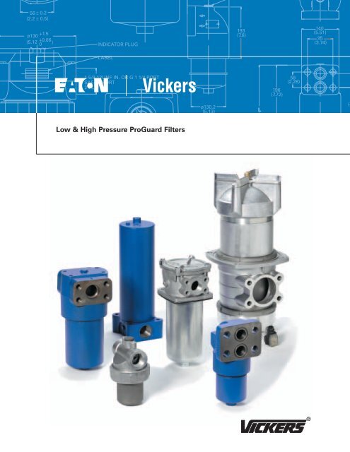
<strong>Low</strong> & <strong>High</strong> Pressure ProGuard <strong>Filters</strong><br />
ø130.2<br />
(5.13)<br />
193<br />
(7.6)<br />
L<br />
196<br />
(7.72)<br />
58<br />
(2.28)<br />
140<br />
(5.51)<br />
95<br />
(3.74)<br />
(4<br />
115<br />
DRAI<br />
(4.5)<br />
CLEARENCE FOR<br />
ELEMENT REMOVAL
Table of Contents<br />
General Information . . . . . . . . . . . . . . . . . . . . . . . . . . . . . . . . . . . . . . . . . . . . . . . . . . . . . . . . . . . . . . . . . . . . . . . . . . . . . . . . . 3<br />
Media/Seal Kit Information . . . . . . . . . . . . . . . . . . . . . . . . . . . . . . . . . . . . . . . . . . . . . . . . . . . . . . . . . . . . . . . . . . . . . . . . . . . . 4<br />
Guidelines for Selecting <strong>Filters</strong> . . . . . . . . . . . . . . . . . . . . . . . . . . . . . . . . . . . . . . . . . . . . . . . . . . . . . . . . . . . . . . . . . . . . . . . . 5<br />
Specific Gravity Corrections for Pressure Drop . . . . . . . . . . . . . . . . . . . . . . . . . . . . . . . . . . . . . . . . . . . . . . . . . . . . . . . . 5<br />
Viscosity Corrections for Pressure Drop . . . . . . . . . . . . . . . . . . . . . . . . . . . . . . . . . . . . . . . . . . . . . . . . . . . . . . . . . . . . . 6<br />
<strong>Low</strong> Pressure <strong>Filters</strong>, Up to 40 bar (600 PSI) . . . . . . . . . . . . . . . . . . . . . . . . . . . . . . . . . . . . . . . . . . . . . . . . . . . . . . . . . . . . . . 7<br />
HV6R . . . . . . . . . . . . . . . . . . . . . . . . . . . . . . . . . . . . . . . . . . . . . . . . . . . . . . . . . . . . . . . . . . . . . . . . . . . . . . . . . . . . . . . . . . . 7<br />
HV3R . . . . . . . . . . . . . . . . . . . . . . . . . . . . . . . . . . . . . . . . . . . . . . . . . . . . . . . . . . . . . . . . . . . . . . . . . . . . . . . . . . . . . . . . . . 10<br />
HF4RT . . . . . . . . . . . . . . . . . . . . . . . . . . . . . . . . . . . . . . . . . . . . . . . . . . . . . . . . . . . . . . . . . . . . . . . . . . . . . . . . . . . . . . . . . 13<br />
OFR-15/30 Series In Line . . . . . . . . . . . . . . . . . . . . . . . . . . . . . . . . . . . . . . . . . . . . . . . . . . . . . . . . . . . . . . . . . . . . . . . . . 16<br />
OFR-60/120 Series In Line . . . . . . . . . . . . . . . . . . . . . . . . . . . . . . . . . . . . . . . . . . . . . . . . . . . . . . . . . . . . . . . . . . . . . . . . 20<br />
OFRS-15 Series Spin-on . . . . . . . . . . . . . . . . . . . . . . . . . . . . . . . . . . . . . . . . . . . . . . . . . . . . . . . . . . . . . . . . . . . . . . . . . . 25<br />
OFRS-25 Series Spin-on . . . . . . . . . . . . . . . . . . . . . . . . . . . . . . . . . . . . . . . . . . . . . . . . . . . . . . . . . . . . . . . . . . . . . . . . . . 29<br />
OFRS-60 Series Spin-on . . . . . . . . . . . . . . . . . . . . . . . . . . . . . . . . . . . . . . . . . . . . . . . . . . . . . . . . . . . . . . . . . . . . . . . . . . 33<br />
HS22 . . . . . . . . . . . . . . . . . . . . . . . . . . . . . . . . . . . . . . . . . . . . . . . . . . . . . . . . . . . . . . . . . . . . . . . . . . . . . . . . . . . . . . . . . . 38<br />
OF3 Series Inlet Strainers . . . . . . . . . . . . . . . . . . . . . . . . . . . . . . . . . . . . . . . . . . . . . . . . . . . . . . . . . . . . . . . . . . . . . . . . 41<br />
10F, 50F & 100F Series Indicating Inlet Strainers . . . . . . . . . . . . . . . . . . . . . . . . . . . . . . . . . . . . . . . . . . . . . . . . . . . . . . 43<br />
<strong>High</strong> Pressure <strong>Filters</strong>, Up to 420 bar (6000 PSI) . . . . . . . . . . . . . . . . . . . . . . . . . . . . . . . . . . . . . . . . . . . . . . . . . . . . . . . . . . 49<br />
HF2P . . . . . . . . . . . . . . . . . . . . . . . . . . . . . . . . . . . . . . . . . . . . . . . . . . . . . . . . . . . . . . . . . . . . . . . . . . . . . . . . . . . . . . . . . . 49<br />
HF3P . . . . . . . . . . . . . . . . . . . . . . . . . . . . . . . . . . . . . . . . . . . . . . . . . . . . . . . . . . . . . . . . . . . . . . . . . . . . . . . . . . . . . . . . . . 52<br />
HF3PS . . . . . . . . . . . . . . . . . . . . . . . . . . . . . . . . . . . . . . . . . . . . . . . . . . . . . . . . . . . . . . . . . . . . . . . . . . . . . . . . . . . . . . . . . 55<br />
HF4P . . . . . . . . . . . . . . . . . . . . . . . . . . . . . . . . . . . . . . . . . . . . . . . . . . . . . . . . . . . . . . . . . . . . . . . . . . . . . . . . . . . . . . . . . . 58<br />
Accessories . . . . . . . . . . . . . . . . . . . . . . . . . . . . . . . . . . . . . . . . . . . . . . . . . . . . . . . . . . . . . . . . . . . . . . . . . . . . . . . . . . . . . . . . 61
Filter Guide<br />
<strong>Low</strong> Pressure <strong>Filters</strong>, Up to 40 bar (600 PSI)<br />
Model Page<br />
HV6R Series In Line . . . . . . . . . . . . . . . . . . . . . . . . . . . 7<br />
Flows to: 1100 L/min (300 USgpm)<br />
Pressures to: 25 bar (350 PSI)<br />
HV3R Series In Line . . . . . . . . . . . . . . . . . . . . . . . . . . 10<br />
Flows to: 280 L/min (75 USgpm)<br />
Pressures to: 50 bar (725 PSI)<br />
HF4RT Series In Tank . . . . . . . . . . . . . . . . . . . . . . . . . . 13<br />
Flows to: 568L/min (150 USgpm)<br />
Pressures to: 7 bar (100 PSI)<br />
OFR 15/30 Series In Line 16<br />
Flows to: 114 L/min (30 USgpm)<br />
Pressures to: 40 bar (600 PSI)<br />
Model Page<br />
OFR 60/120 Series In Line . . . . . . . . . . . . . . . . . . . . . 20<br />
Flows to: 450 L/min (120 USgpm)<br />
Pressures to: 27,6 bar (400 PSI)<br />
OFRS15 Series Spin-on . . . . . . . . . . . . . . . . . . . . . . . . 25<br />
Flows to: 60 L/min (15 USgpm)<br />
Pressures to: 7 bar (100 PSI)<br />
OFRS25 Series Spin-on . . . . . . . . . . . . . . . . . . . . . . . 29<br />
Flows to: 95 L/min (25 USgpm)<br />
Pressures to: 7 bar (100 PSI)<br />
OFRS60 Spin-on . . . . . . . . . . . . . . . . . . . . . . . . . . . . . 33<br />
Flows to: 225 L/min (60 USgpm)<br />
Pressures to: 7 bar (100 PSI)<br />
EATON <strong>Low</strong> & <strong>High</strong> Pressure ProGuard <strong>Filters</strong> - Filter Guide V-FF-MC-<strong>0001</strong>-E1 June 2002 1
Filter Guide<br />
<strong>Low</strong> Pressure <strong>Filters</strong>, Up to 40 bar (600 PSI)<br />
Model Page<br />
HS22 Series Twin Spin-on . . . . . . . . . . . . . . . . . . . . . 38<br />
Flows to: 450 L/min (120 USgpm)<br />
Pressures to: 14 bar (200 PSI)<br />
OF3 Inlet Strainer . . . . . . . . . . . . . . . . . . . . . . . . . . . . 41<br />
Flows to: 379 L/min (100 USgpm)<br />
10F/50F/100F Series Indicating Inlet Strainers . . . . . 43<br />
Flows to: 700 L/min (185 USgpm)<br />
Pressures to: 20,7 bar (300 PSI)<br />
2 EATON <strong>Low</strong> & <strong>High</strong> Pressure ProGuard <strong>Filters</strong> - Filter Guide V-FF-MC-<strong>0001</strong>-E1 June 2002<br />
<strong>High</strong> Pressure <strong>Filters</strong>, Up to 420 bar (6000 PSI)<br />
Model Page<br />
HF2P Series In Line <strong>and</strong> Subplate . . . . . . . . . . . . . . . 49<br />
Flows to: 90 L/min (24 USgpm)<br />
Pressures to: 210 bar (3000 PSI)<br />
HF3P Series In Line . . . . . . . . . . . . . . . . . . . . . . . . . . . 52<br />
Flows to: 570 L/min (150 USgpm)<br />
Pressures to: 420 bar (6000 PSI)<br />
HF3PS Series Side Mount . . . . . . . . . . . . . . . . . . . . . 55<br />
Flows to: 570 L/min (150 USgpm)<br />
Pressures to: 310 bar (4500 PSI)<br />
HF4P Series In Line <strong>and</strong> Subplate . . . . . . . . . . . . . . . 58<br />
Flows to: 570 L/min (150 USgpm)<br />
Pressures to: 345 bar (5000 PSI)
General Information<br />
<strong>High</strong> Performance Control<br />
<strong>Vickers</strong> high performance filters are<br />
designed for low <strong>and</strong> high <strong>pressure</strong><br />
applications. With flows rated to 1100<br />
L/min (300 gpm) <strong>and</strong> <strong>pressure</strong>s rated to<br />
420 bar (6000 PSI), <strong>Vickers</strong> provides a<br />
variety of options to implement<br />
Systemic Contamination ControlSM in<br />
hydraulic systems. To achieve Target<br />
Cleanliness Levels, filters are available<br />
in a wide range of:<br />
•Port sizes<br />
• Bypass valves<br />
• ∆P indicators<br />
• Media grades<br />
Each grade of <strong>Vickers</strong> high e<strong>ff</strong>iciency<br />
filters is thoroughly multipass tested<br />
(ISO 4572, ß ≥200) <strong>and</strong> rated to<br />
achieve cleanliness levels in accordance<br />
with ISO 4406. For assistance in<br />
selecting a Target Cleanliness Level,<br />
consult American National St<strong>and</strong>ard<br />
Institute ANSI (NFPA/JIC) T2.24.1-1991<br />
or your local Eaton representative.<br />
The Systemic Approach to<br />
Contamination Control<br />
For a hydraulic or oil lubricated<br />
machine, the development of a Target<br />
Cleanliness Level <strong>and</strong> the plan to<br />
achieve it is as much a part of system<br />
design as the selection of the pump,<br />
valves, actuators or bearings.<br />
Proper selection <strong>and</strong> placement of<br />
contamination control devices in<br />
a system to attain the targeted<br />
cleanliness eliminates (the root cause)<br />
up to 80% of hydraulic system failures.<br />
Additionally, the system cleanliness<br />
approach assures the user of the<br />
hydraulic system a cost e<strong>ff</strong>ective<br />
approach to contamination control that<br />
allows the price of the filters <strong>and</strong><br />
elements to be quickly recovered by<br />
the savings of improved performance,<br />
increased component life, increased<br />
oil life, increased uptime <strong>and</strong> fewer<br />
repairs.To stress the interacting<br />
relationship between component<br />
design, system design, filter<br />
performance <strong>and</strong> filter replacement,<br />
Eaton has named our approach to<br />
filters <strong>and</strong> filtration ‘‘The Systemic<br />
Approach to Contamination Control.’’<br />
This approach has three steps:<br />
• Set a target cleanliness level.<br />
Using the <strong>Vickers</strong> Target Cleanliness<br />
Worksheet (#578), it is easy to<br />
determine the target ISO Cleanliness<br />
Level. This target is based on the<br />
application’s components <strong>and</strong> system<br />
dynamics.<br />
• Select filters <strong>and</strong> filter elements to<br />
achieve the target.<br />
The Systemic Approach to<br />
Contamination Control (#561) o<strong>ff</strong>ers<br />
options to consider when selecting<br />
our high e<strong>ff</strong>iciency filters, such as<br />
the options available for location<br />
<strong>and</strong> sizing of filters in the system to<br />
achieve a specified target cleanliness<br />
level.<br />
• Monitor the system to ensure the<br />
target is maintained.<br />
The <strong>Vickers</strong> Fluid Analysis Laboratory<br />
<strong>and</strong> the Target-Pro Portable Particle<br />
Counter report the fluid cleanliness<br />
in the three digit ISO Code<br />
System Cleanliness Ratings<br />
Code Typical ISO 4406 Number of times pump Typical filter placements<br />
cleanliness level achieved* flow passes through filter<br />
Cleanliness level format,<br />
corresponding to the 2, 5 <strong>and</strong> 15<br />
micron particle counts. From this<br />
information, it is possible to<br />
determine whether the system has<br />
the clean fluid it needs for long,<br />
dependable operation.<br />
Supporting Literature<br />
• <strong>Vickers</strong> Reservoir Vent <strong>Filters</strong><br />
#5027/EN/0196/P<br />
• <strong>Vickers</strong> CleanCart Portable Filtering<br />
Transfer Cart #601<br />
• <strong>Vickers</strong> Fluid Analysis Service #588<br />
• <strong>Vickers</strong> Guide to Alternative Fluids<br />
#579<br />
• <strong>Vickers</strong> Recommended Sampling<br />
Chart #603<br />
• <strong>Vickers</strong> Return in Investment:<br />
ProActive Maintenance #707<br />
• The Systemic Approach to<br />
Contamination Control #561<br />
• <strong>Vickers</strong> Target Cleanliness Worksheet<br />
#578<br />
• <strong>Vickers</strong> Target-Pro Particle Counter<br />
#709<br />
• <strong>Vickers</strong> Water Contamination<br />
Solutions #5026/EN/0196/A<br />
• ANSI Systems St<strong>and</strong>ards for<br />
Stationary Industrial Machinery #675<br />
03 14/12/10 2.0 Full flow <strong>pressure</strong> <strong>and</strong> return line<br />
15/13/11 1.5 Full flow <strong>pressure</strong> or return <strong>and</strong> recirculation loop<br />
16/14/12 1.0 Full flow <strong>pressure</strong> or return line<br />
17/15/13 .5 Recirculation loop sized to 10% of system vol/min<br />
05 16/14/12 2.0 Full flow <strong>pressure</strong> <strong>and</strong> return line<br />
17/15/13 1.5 Full flow <strong>pressure</strong> or return <strong>and</strong> recirculation loop<br />
18/16/14 1.0 Full flow <strong>pressure</strong> or return line<br />
19/17/15 .5 Recirculaton loop sized to 10% of system vol/min<br />
10 18/16/14 2.0 Full flow <strong>pressure</strong> <strong>and</strong> return line<br />
19/17/14 1.5 Full flow <strong>pressure</strong> or return <strong>and</strong> recirculation loop<br />
20/18/15 1.0 Full flow <strong>pressure</strong> or return line<br />
21/19/16 .5 Recirculation loop sized to 10% of system vol/min<br />
* For assistance in determining the Target Cleanliness Level <strong>and</strong> selecting the proper filter element consult your local Eaton representative.<br />
EATON <strong>Low</strong> & <strong>High</strong> Pressure ProGuard <strong>Filters</strong> - General Information V-FF-MC-<strong>0001</strong>-E1 June 2002 3
Media/Seal Kit General Information<br />
Element:<br />
Five Layer Media<br />
<strong>Vickers</strong> Pak Construction<br />
All <strong>Vickers</strong> filter elements are<br />
constructed with five layers, making<br />
them durable <strong>and</strong> highly e<strong>ff</strong>icient.<br />
1. <strong>High</strong> strength support<br />
2. Non woven synthetic di<strong>ff</strong>user layer<br />
3. <strong>Vickers</strong> glass micro fiber media<br />
with special resin binder<br />
4. Non woven synthetic di<strong>ff</strong>user<br />
(drainage) layer<br />
5. <strong>High</strong> strength support<br />
1<br />
2<br />
3<br />
H-Pak Construction<br />
For systems where a bypass valve is<br />
undesirable, such as servo systems,<br />
the H-Pak media provides high collapse<br />
rated housing <strong>pressure</strong>s. H-Pak media<br />
construction utilizes 304 stainless steel<br />
inner <strong>and</strong> outer mesh support along<br />
with heavier core tubes <strong>and</strong> media<br />
support to protect the system.<br />
C-Pak Construction<br />
C-Pak media uses five layer construction.<br />
C-Pak incorporates epoxy coated carbon<br />
steel as the two outer face layers to<br />
retain the inner media pak layers.<br />
R-Pak Construction<br />
The R-Pak spin-on filter elements are<br />
designed for low clean <strong>pressure</strong> drop<br />
<strong>and</strong> high e<strong>ff</strong>iciency. R-Pak incorporates<br />
a five layer media construction with<br />
outer layers of epoxy coated carbon<br />
steel wire to retain the inner media<br />
pak layers.<br />
L-Pak Construction<br />
The L-Pak is specially designed for<br />
lubrication applications. Using the<br />
same five layer construction as the<br />
C-Pak, the L-Pak also has a deep pleat<br />
construction to maximize element life<br />
in steady flow, low pulsation systems.<br />
4 EATON <strong>Low</strong> & <strong>High</strong> Pressure ProGuard <strong>Filters</strong> - Media/Seal Kit Information V-FF-MC-<strong>0001</strong>-E1 June 2002<br />
Seal Kits<br />
Note<br />
Seal kits include all soft goods to fully<br />
service a unit.<br />
Series Seal Seal Kit Part #<br />
Type<br />
HV6R Buna-N 3039688<br />
Viton-A* 3039689<br />
HV3R Buna-N 3039690<br />
Viton-A 3039691<br />
HF4RT Buna-N 3039692<br />
Viton-A 3039693<br />
HF2P Buna-N 3039694<br />
Viton-A 3039695<br />
HF3P Buna-N 3039696<br />
Viton-A 3039697<br />
HF3PS Buna-N 3039698<br />
Viton-A 3039699<br />
HF4P Buna-N 3039700<br />
Viton-A 3039701<br />
OFR60/ Buna-N 590021 (Bowl<br />
120 Viton-A 591761 seal only)<br />
OFR15/ Buna-N 226214 (Bowl<br />
30 Viton-A 262422 seal only)<br />
* Viton is a registered trademark of E.I. Dupont
Guidelines for Selecting <strong>Filters</strong><br />
Target Cleanliness<br />
Using the <strong>Vickers</strong> Target Cleanliness<br />
Worksheet (#578), it is easy to<br />
determine the target ISO Cleanliness<br />
Level for a system. This target<br />
is based on the application’s<br />
components <strong>and</strong> system dynamics.<br />
Placement <strong>and</strong> Media<br />
Use the chart below to help select<br />
the appropriate filter placement <strong>and</strong><br />
grade of media to achieve the target<br />
cleanliness level. For more detail,<br />
consult “The Systemic Approach to<br />
Contamination Control”, your Eaton<br />
representative, or the ANSI Systems<br />
St<strong>and</strong>ards for Stationary Industrial<br />
Machinery.<br />
Filter Placements<br />
The chart below helps engineers select<br />
the grade of <strong>Vickers</strong> media <strong>and</strong> the<br />
filter placement(s) that will achieve the<br />
required target cleanliness. It assumes<br />
the system will experience ‘‘average’’<br />
ingression <strong>and</strong> that maintenance of the<br />
system will be consistent with current<br />
technology.<br />
If in operation the system is running<br />
dirtier than expected, corrective actions<br />
should be initiated. Suggested<br />
corrective actions are:<br />
• Check the indicator to see if the<br />
filters are on by-pass.<br />
• Check the sources of ingression <strong>and</strong><br />
correct problems.<br />
• Check that the filters are positioned<br />
properly to see maximum fluid flow.<br />
• Consider using a finer Pak grade.<br />
• Add a filter to the system.<br />
Note<br />
All systems need a sealed reservoir<br />
with vent port filtration.<br />
CAUTION<br />
Before servicing the<br />
element, the bleed plug in<br />
filter housing must be<br />
•<br />
loosened to relieve<br />
<strong>pressure</strong>. This will minimize<br />
fluid overflow.<br />
Housing<br />
The selected housing should be rated<br />
within the required flow <strong>and</strong> <strong>pressure</strong>s<br />
of the application.<br />
Important: If the system fluid’s specific<br />
gravity (SG) is greater than 0.9 (for<br />
example, water glycol), the housing<br />
<strong>pressure</strong> drop (∆P) should be corrected<br />
for the actual application.<br />
Recommended Recommended Recommended<br />
filter placement for filter placement for filter placement for<br />
Target high ingression systems with high ingression<br />
Cleanliness systems with fixed variable volume systems with<br />
volume pumps pumps variable volume<br />
pumps<br />
Specific Gravity Corrections<br />
for Pressure Drop<br />
The filter housing flow curves in this<br />
catalog can be adjusted using the<br />
following equation:<br />
Adjusted ∆PHousing = ∆P x Actual SG<br />
Curve<br />
0.9<br />
Bypass Valve<br />
Bypass valve selection is based<br />
upon system requirements. According<br />
to ANSI St<strong>and</strong>ard 12.2.6, filter<br />
assemblies whose elements cannot<br />
withst<strong>and</strong> full system di<strong>ff</strong>erential<br />
<strong>pressure</strong> without damage should be<br />
equipped with bypass valves. Generally,<br />
a higher bypass <strong>pressure</strong> setting will<br />
allow for longer element life.<br />
Some systems require filtration<br />
with no bypass, such as servo<br />
applications. <strong>Vickers</strong> H-Pak media<br />
is recommended for non-bypass<br />
systems.<br />
Full flow <strong>pressure</strong> Full flow <strong>pressure</strong> Pressure line/ Pressure line plus Recirculating loop Recirculating loop<br />
line or return line line <strong>and</strong> return line recirculating loop return line plus at 20% of system at 10% of system<br />
at 20% of system recirculating loop volume per minute volume per<br />
volume per minute minute<br />
14/12/10 – 03 03 03 – –<br />
15/13/11 – 03 03 05 – –<br />
16/14/12 03 05 05 05 03 –<br />
17/15/13 03 05 05 05 or 10 03 03<br />
18/16/14 05 10 05 or 10 10 05 03<br />
19/17/15 05 or 10 10 10 10 05 or 10 05<br />
EATON <strong>Low</strong> & <strong>High</strong> Pressure ProGuard <strong>Filters</strong> - Guidelines for Selecting <strong>Filters</strong> V-FF-MC-<strong>0001</strong>-E1 June 2002 5
Guidelines for Selecting <strong>Filters</strong><br />
Indicator<br />
To meet ANSI St<strong>and</strong>ard 12.2.5, filter<br />
assemblies should have a device<br />
to indicate when the filter requires<br />
servicing. Per ANSI St<strong>and</strong>ard 12.2.6,<br />
the indicator should “trip” at<br />
approximately 80% of the bypass<br />
<strong>pressure</strong> setting. If using a non-bypass<br />
housing, an indicator setting<br />
of approximately 7 bar (100 PSI)<br />
is recommended.<br />
Element<br />
The <strong>Vickers</strong> element media grade<br />
should be selected to achieve the<br />
Target Cleanliness Level. The<br />
<strong>Vickers</strong> media construction should<br />
be chosen based upon system<br />
requirements such as flow<br />
characteristics, <strong>pressure</strong> surges<br />
<strong>and</strong> specific application conditions.<br />
Important: If the system fluid’s<br />
specific gravity (SG) is greater than<br />
0.9 (for example, water glycol), the<br />
element <strong>pressure</strong> drop (∆P) should<br />
be corrected.<br />
Indicator Switch Schematic<br />
Wiring Diagram<br />
C<br />
Note<br />
The female connector is to be furnished<br />
by the customer.<br />
Note<br />
When fitting indicator, torque to 41-47 Nm.<br />
WHITE<br />
NO<br />
NC<br />
BLACK<br />
RED<br />
GD<br />
1 2<br />
Viscosity Corrections for<br />
Pressure Drop<br />
The element flow curves can be<br />
adjusted using the following equations:<br />
Adjusted Clean ∆P Element =<br />
Actual viscosity in cP÷29 x ∆P Curve<br />
Actual viscosity in cSt/32 x Actual SG<br />
÷0.9 x ∆P Curve<br />
Actual viscosity in SUS/150 x Actual<br />
SG ÷ 0.9 x ∆P Curve<br />
A good “rule of thumb”: To ensure<br />
satisfactory element life, the clean<br />
element <strong>pressure</strong> drop should<br />
generally be less than or equal to<br />
40 percent of the indicator’s rated<br />
di<strong>ff</strong>erential <strong>pressure</strong>:<br />
∆P Element ≤0.4 x ∆P Indicator<br />
The best way to extend element<br />
service life is to minimize ingression<br />
(vents, seals, cylinder rods) <strong>and</strong><br />
maintain system cleanliness at or<br />
below the Target Cleanliness Level.<br />
GREEN<br />
Hirschmann (DIN 43650 Type AM) Receptacle<br />
3<br />
GD<br />
1 2<br />
3<br />
PIN<br />
ARRANGEMENT<br />
TO<br />
SYSTEM<br />
6 EATON <strong>Low</strong> & <strong>High</strong> Pressure ProGuard <strong>Filters</strong> - Guidelines for Selecting <strong>Filters</strong> V-FF-MC-<strong>0001</strong>-E1 June 2002<br />
Selecting a Model Code<br />
Electrical<br />
Switch: SPDT<br />
Rating: 7 amps, resistive<br />
4 amps, inductive<br />
2 amps, lamp load<br />
@28 VDC, 115 VAC 60 Hz &<br />
220 VAC 50 Hz or 60 Hz<br />
C<br />
WHITE<br />
NO<br />
NC<br />
ORANGE<br />
RED<br />
Note<br />
Model codes for housings only<br />
contain eight designations;<br />
model codes for filter assemblies<br />
(housing <strong>and</strong> element) contain ten<br />
designations.<br />
To select a filter housing with the<br />
element included, attach the Element<br />
Construction <strong>and</strong> Fluid Cleanliness<br />
Rating designators at the end of the<br />
Housing Model Code. For example:<br />
HV6R MT 4 AN B 8 L 05<br />
Include<br />
To select a filter housing only (with<br />
no element), omit the Element<br />
Construction <strong>and</strong> Fluid Cleanliness<br />
Rating designators at the end of the<br />
Housing Model Code. For example:<br />
HV6R MT 4 AN B 8<br />
To select a filter element only, use the<br />
Element Model Code. For example:<br />
VO41 1 B 8 L 05<br />
Note<br />
Refer to page 63 for Di<strong>ff</strong>erential<br />
Pressure Indicator Selection Chart.<br />
1<br />
2<br />
3<br />
BLACK<br />
GREEN<br />
Brad Harrison (41512) Receptacle<br />
5<br />
4<br />
{<br />
1<br />
2<br />
GD<br />
3<br />
5<br />
4<br />
PIN<br />
ARRANGEMENT<br />
TO<br />
SYSTEM
HV6R Series <strong>Filters</strong><br />
Flows to 1100 L/min (300 USgpm) — Pressures to 25 bar (350 PSI)<br />
Features <strong>and</strong> Benefits<br />
• Designed to comply with ANSI<br />
specifications <strong>and</strong> ISO cleanliness<br />
st<strong>and</strong>ards.<br />
• Easy to remove cap to facilitate<br />
element change <strong>and</strong> minimize<br />
spillage.<br />
• Vent <strong>and</strong> drain ports to facilitate<br />
maintenance <strong>and</strong> system start-up.<br />
• Visual, electrical, <strong>and</strong> electrical<br />
indicators with lamp options for<br />
system design flexibility.<br />
• <strong>High</strong> e<strong>ff</strong>iciency replacement<br />
elements in st<strong>and</strong>ard configurations<br />
(C-Pak) <strong>and</strong> deep pleat elements for<br />
maximum service life (L-Pak).<br />
Design Specifications<br />
Rated flow:<br />
Length 5 750 L/min<br />
(200 USgpm)<br />
Length 8 1135 L/min<br />
(300 USgpm)<br />
Housing & Compatible with most<br />
Element petroleum oil,<br />
Compatibility: oil-in-water <strong>and</strong><br />
water-in-oil fluids.<br />
Optional seals available<br />
for phosphate esters.<br />
Temp range: -26°C to +121°C<br />
(-15°F to +250°F)<br />
Pressure rating:<br />
Operating 25 bar (360 PSI)<br />
Proof 37 bar (540 PSI)<br />
Burst 150 bar (2175 PSI)<br />
Fatigue 25 bar (360 PSI)<br />
Material:<br />
Head Aluminum<br />
Housing Aluminum<br />
Lid Aluminum<br />
Dry weight: (Approximate)<br />
Length 5 21kg (46lbs)<br />
Length 8 30 kg (66lbs)<br />
Filter Assembly Model Code<br />
HV6R 1 MT 4 LN B 8 C 05<br />
1 Filter Series - New<br />
HV6R<br />
1 2 3 4 5<br />
2 Element Collapse Rating<br />
1 - 150 PSI <strong>Low</strong> Collapse<br />
3 Port options<br />
MT - 4" SAE 4 Bolt Flange with Metric<br />
threads (M16 bolts provided)<br />
4 Valve options<br />
1 - Non-Bypass<br />
2 - Bypass set at 25 PSI<br />
cracking <strong>pressure</strong><br />
4 - Bypass set at 43 PSI<br />
cracking <strong>pressure</strong><br />
5 Indicator options<br />
First Designator - Indicator Type<br />
A - Visual 70 PSI<br />
J - No Indicator (plug)<br />
K - Visual 15 PSI<br />
L - Visual 30 PSI<br />
Q - Electrical 15 PSI<br />
R - Electrical 30 PSI<br />
U - Electrical 70 PSI<br />
Second Designator - Electrical<br />
Receptical<br />
B - Brad Harrison<br />
H - Hirshman<br />
J - Hirshman with 24 volt light<br />
K - Hirshman with 115 volt light<br />
L - Hirshman with 230 volt light<br />
N - No Connector - use with visual<br />
indicators <strong>and</strong> “J”<br />
6 Seal material<br />
B - Buna-N<br />
V - Viton-A<br />
Viton is a registered trademark of E.I. DuPont<br />
7 Element Assembly<br />
length length<br />
5 - 407mm (16") 472mm (18.6")<br />
8 - 981mm (39") 1056mm (41.6")<br />
8 Element construction<br />
C - St<strong>and</strong>ard Construction<br />
L - Deep pleat construction<br />
9<br />
6 7 8 9<br />
Fluid cleanliness rating<br />
Target fluid<br />
Code cleanliness level<br />
03 16/14/12 or better<br />
05 18/16/14 or better<br />
10 20/18/15 or better<br />
20 22/19/16 or better<br />
The table assumes limited<br />
ingression/single pass of pump<br />
flow through element. For detailed<br />
assistance, see “The Systemic<br />
Approach to Contamination Control”<br />
or contact your local Eaton<br />
representative.<br />
EATON <strong>Low</strong> & <strong>High</strong> Pressure ProGuard <strong>Filters</strong> - HV6R V-FF-MC-<strong>0001</strong>-E1 June 2002 7
Dimensions<br />
HV6R Housing<br />
mm (inch)<br />
ø29<br />
(11.42)<br />
ø18<br />
(0.71)<br />
Bracket ref. page 62<br />
Filter assembly may<br />
be lowered through<br />
the bracket <strong>and</strong><br />
secured with 5/8"-11x1 1/4"<br />
screws (4).<br />
77.8<br />
(3.06)<br />
Clogging<br />
Indicator<br />
140<br />
(5.51)<br />
260<br />
(10.24)<br />
130<br />
(5.12)<br />
15x1.5<br />
Vent Plug G 1/2<br />
280<br />
(11.02)<br />
140<br />
(5.51)<br />
280<br />
(11.02)<br />
Inlet<br />
4" SAE Flange,<br />
Code 61<br />
Outlet<br />
8 EATON <strong>Low</strong> & <strong>High</strong> Pressure ProGuard <strong>Filters</strong> - HV6R V-FF-MC-<strong>0001</strong>-E1 June 2002<br />
The lower housing may<br />
be rotated to locate the<br />
indicator at the 9 o'clock or<br />
6 o'clock position (90˚ ccw or 180˚)<br />
Filter Housing/Bypass Valve Flow Data<br />
Flow versus <strong>pressure</strong> drop: 150 SUS (32 cSt) oil with specific gravity of ≤ 0.9<br />
(See page 5 for specific gravity corrections for <strong>pressure</strong> drop.)<br />
Housing Bypass Valve<br />
Pressure drop - bar (PSID)<br />
(2.9) 0,2<br />
0,15<br />
(1.5) 0,10<br />
0,05<br />
(58) 4,0<br />
110<br />
(4.33)<br />
Refer to<br />
Model Code<br />
Drain Plug G 3/4<br />
195<br />
(7.68)<br />
0<br />
0 300 600 900 1200 1500<br />
0<br />
0 300 600 900 1200 1500<br />
(79) (238) (396)<br />
(79) (238) (396)<br />
Flow Rate - L/min (USgpm)<br />
Flow Rate - L/min (USgpm)<br />
Pressure drop - bar (PSID)(100)<br />
7,0<br />
6,0<br />
5,0<br />
3,0<br />
2,0<br />
(15) 1,0
041 Series Replacement Filter Elements<br />
Element Model Code<br />
V041 1 B 5 L 03<br />
1 2 3 4 5 6<br />
1 Filter element<br />
V041 - For use with HV6R series<br />
housings<br />
2 Element collapse rating<br />
1 - 150 PSI <strong>Low</strong> Collapse<br />
NOTE: L-Pak elements are rated at 100 PSI<br />
collapse. If used in a Non-Bypass housing,<br />
a monitored di<strong>ff</strong>erential <strong>pressure</strong> indicator<br />
(70 PSI max.) should be used.<br />
(Indicator option A, B, I, U, or V)<br />
Design Specifications<br />
Rated flow: 568 L/min (150 USgpm)<br />
with bowl length 5<br />
O-ring per<br />
AS568-243 typ.<br />
Refer to<br />
model code<br />
1135 L/min<br />
(300 USgpm)<br />
with bowl length 8<br />
Housing & Compatible with most<br />
Element petroleum oil, water<br />
Compatibility: glycol, oil-in-water <strong>and</strong><br />
water-in-oil fluids.<br />
Optional seals available<br />
for phosphate esters.<br />
Construction: C-Pak or L-Pak<br />
Temp range: -26°C to +121°C<br />
(-15°F to +250°F)<br />
Dimensions<br />
mm (inch)<br />
152,4 dia. typ<br />
(6.00)<br />
3 Seal material<br />
B - Buna-N<br />
V - Viton-A<br />
Viton is a registered trademark of E.I. DuPont<br />
4 Element length<br />
mm (inch)<br />
5 - 406 (16)<br />
8 - 990 (39)<br />
5<br />
0411 C-Pak 406 (16) length<br />
Flow Rate - USgpm<br />
50 100 150 200<br />
0,7<br />
0,6<br />
0,4<br />
0,3<br />
0,1<br />
0<br />
0 100 300<br />
C03<br />
500<br />
10<br />
05 8<br />
10<br />
6<br />
4<br />
20 2<br />
700<br />
Flow Rate - L/min<br />
Pressure drop - bar<br />
0411 C-Pak 990 (39) length<br />
Flow Rate - USgpm<br />
50 100 150 200 250 300<br />
0,6<br />
0,4<br />
0,3<br />
0,1<br />
C03<br />
8<br />
05<br />
6<br />
10<br />
4<br />
20<br />
2<br />
0<br />
0 250 500 750 1000<br />
Flow Rate - L/min<br />
Pressure drop - bar<br />
Element construction<br />
C - C-Pak (grade 3, 5, 10, 20)<br />
L - L-Pak (grade 3, 5, 10, 20)<br />
Filter Element Flow Data<br />
mm (inch)<br />
Flow versus <strong>pressure</strong> drop:<br />
150 SUS (32 cSt) oil with specific gravity of ≤ 0.9<br />
(See page 6 for viscosity corrections for <strong>pressure</strong> drop.)<br />
Pressure drop - PSID<br />
Pressure drop - PSID<br />
6 Fluid cleanliness ratings<br />
Target fluid<br />
Code cleanliness level<br />
03 16/14/12 or better<br />
05 18/16/14 or better<br />
10 20/18/15 or better<br />
20 22/19/16 or better<br />
The table assumes limited<br />
ingression/single pass of pump<br />
flow through element. For detailed<br />
assistance, see “The Systemic<br />
Approach to Contamination Control”<br />
or contact your local Eaton<br />
representative.<br />
0411 L-Pak 406 (16) length<br />
Flow Rate - USgpm<br />
50 100 150 200<br />
0,7<br />
L03 10<br />
0,6<br />
0,4<br />
05<br />
8<br />
6<br />
0,3<br />
10 4<br />
0,1<br />
0<br />
0 100 300 500<br />
20 2<br />
700<br />
Flow Rate - L/min<br />
Pressure drop - bar<br />
0411 L-Pak 990 (39) length<br />
Flow Rate - USgpm<br />
50 100 150 200 250 300<br />
Pressure drop - bar<br />
0,6<br />
0,4<br />
0,3<br />
0,1<br />
0<br />
0<br />
05<br />
8<br />
L03 6<br />
10 4<br />
2<br />
20<br />
250 500 750 1000<br />
Flow Rate - L/min<br />
EATON <strong>Low</strong> & <strong>High</strong> Pressure ProGuard <strong>Filters</strong> - HV6R V-FF-MC-<strong>0001</strong>-E1 June 2002 9<br />
Pressure drop - PSID<br />
Pressure drop - PSID
HV3R Series <strong>Filters</strong><br />
Flows to 280 L/min (75 USgpm) — Pressures to 50 bar (725 PSI)<br />
Features <strong>and</strong> Benefits<br />
• Designed to comply with ANSI<br />
specifications <strong>and</strong> ISO cleanliness<br />
st<strong>and</strong>ards.<br />
• Visual, electrical, <strong>and</strong> electrical<br />
indicators with lamp options for<br />
system design flexibility<br />
• Fully serviceable without tools<br />
• Zero leak by-pass valve construction.<br />
• Wide range of element lengths for<br />
maximum design flexibility<br />
• <strong>High</strong> e<strong>ff</strong>iciency replacement<br />
elements in st<strong>and</strong>ard configurations<br />
(C-Pak) to meet Target Cleanliness<br />
Levels<br />
• <strong>High</strong> collapse elements available for<br />
non-bypass applications.<br />
Design Specifications<br />
Rated flow:<br />
Length 1 160 L/min (42 USgpm)<br />
Length 2 240 L/min (63 USgpm)<br />
Length 4 280 L/min (74 USgpm)<br />
Housing & Compatible with most<br />
Element petroleum oil,<br />
Compatibility: oil-in-water <strong>and</strong><br />
water-in-oil fluids.<br />
Optional seals available<br />
for phosphate esters.<br />
Temp range: -26°C to +121°C<br />
(-15°F to +250°F)<br />
Pressure rating:<br />
Operating 50 bar (725 PSI)<br />
Proof 75 bar (1090 PSI)<br />
Burst 150 bar (2175 PSI)<br />
Fatigue 50 bar (725 PSI)<br />
Material:<br />
Head Aluminum<br />
Bowl Carbon Steel<br />
Collar Carbon Steel<br />
Dry weight: (Approximate)<br />
Length 1 2.3 kg (5.1 lbs)<br />
Length 2 2.5 kg (5.5 lbs)<br />
Length 4 3.4 kg (7.5 lbs)<br />
Filter Assembly Model Code<br />
1 Filter Series<br />
HV3R<br />
10 EATON <strong>Low</strong> & <strong>High</strong> Pressure ProGuard <strong>Filters</strong> - HV3R V-FF-MC-<strong>0001</strong>-E1 June 2002<br />
HV3R 1 SC 4 LN B 2 C 05<br />
1 2 3 4 5<br />
2 Element Collapse Rating<br />
1 - 250 PSI <strong>Low</strong> Collapse<br />
4 - 3000 PSI <strong>High</strong> Collapse<br />
Port options<br />
BC - G 1-1/4 to ISO 228<br />
SC - 1.625 - 12UN SAE-20 str. Thd.<br />
(11 3<br />
/4" tube)<br />
4 Valve options<br />
1 - Non-Bypass<br />
3 - Bypass set at 25 PSI<br />
cracking <strong>pressure</strong><br />
4 - Bypass set at 43 PSI<br />
cracking <strong>pressure</strong><br />
5 Indicator options<br />
First Designator - Indicator Type<br />
A - Visual 70 PSI<br />
J - No Indicator (plug)<br />
K - Visual 15 PSI<br />
L - Visual 30 PSI<br />
Q - Electrical 15 PSI<br />
R - Electrical 30 PSI<br />
U - Electrical 70 PSI<br />
Second Designator - Electrical<br />
Receptical<br />
B - Brad Harrison<br />
H - Hirshman<br />
J - Hirshman with 24 volt light<br />
K - Hirshman with 115 volt light<br />
L - Hirshman with 230 volt light<br />
N - No Connector - use with visual<br />
indicators <strong>and</strong> “J”<br />
6 7 8 9<br />
6 Seal material<br />
B - Buna-N<br />
V - Viton-A<br />
Viton is a registered trademark of E.I. DuPont<br />
7 Element Assembly<br />
length length<br />
1 - 114mm (4.5") 207mm (8.15")<br />
2 - 173mm (6.8") 266mm (10.47")<br />
4 - 356mm (14") 447mm (17.6")<br />
8 Element construction<br />
C - 250 PSI <strong>Low</strong> Collapse<br />
H - 3000 PSI <strong>High</strong> Collapse<br />
9 Fluid cleanliness rating<br />
Target fluid<br />
Code cleanliness level<br />
03 16/14/12 or better<br />
05 18/16/14 or better<br />
10 20/18/15 or better<br />
20 22/19/16 or better<br />
The table assumes limited<br />
ingression/single pass of pump<br />
flow through element. For detailed<br />
assistance, see “The Systemic<br />
Approach to Contamination Control”<br />
or contact your local Eaton<br />
representative.
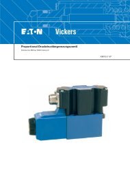
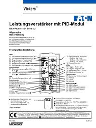
Dimensions<br />
HV3R Housing<br />
mm (inch)<br />
Housing<br />
46.4<br />
(1.83)<br />
7.4<br />
(0.29)<br />
Refer to<br />
Model Code<br />
50.0 (1.97)<br />
Clearance for<br />
Element Removal<br />
0 50 100 150 200 250 300<br />
(13) (40) (66)<br />
Flow Rate - L/min (USgpm)<br />
56±<br />
0.2<br />
(2.2 ± 0.5)<br />
ø130 +1.5<br />
+0.06<br />
(5.12<br />
0 )<br />
ø82.5<br />
(3.25)<br />
ø125<br />
(4.92)<br />
Mounting Holes<br />
3/8 - 24 X 14 (0.56) Deep with SC (SAE-20) port option<br />
M10 with BC (G 1-1/4)port option<br />
Indicator Plug<br />
Label<br />
Filter Housing/Bypass Valve Flow Data<br />
Flow versus <strong>pressure</strong> drop: 150 SUS (32 cSt) oil with specific gravity of ≤ 0.9<br />
(See page 5 for specific gravity corrections for <strong>pressure</strong> drop.)<br />
Pressure drop - bar (PSID)<br />
1,4<br />
(17) 1,2<br />
1,0<br />
(12) 0,8<br />
0,6<br />
(6) 0,4<br />
0,2<br />
1 5/8-12UNF in. or G 1 1/4 port<br />
SAE-20 port<br />
2 PL'S<br />
Bypass Valve<br />
Pressure drop - bar (PSID)<br />
5,0<br />
(58) 4,0<br />
3,0<br />
(29) 2,0<br />
1,0<br />
0<br />
0 50<br />
(13)<br />
100 150<br />
(40)<br />
200<br />
Flow Rate - L/min (USgpm)<br />
EATON <strong>Low</strong> & <strong>High</strong> Pressure ProGuard <strong>Filters</strong> - HV3R V-FF-MC-<strong>0001</strong>-E1 June 2002 11
V3R Series Replacement Filter Elements<br />
Element Model Code<br />
V3R B 1 C 05<br />
1<br />
Filter element<br />
V3R - For use with HV3R series<br />
housings<br />
2<br />
Seal material<br />
B - Buna-N<br />
V - Viton-A<br />
Viton is a registered trademark of E.I. DuPont<br />
Design Specifications<br />
Rated flow:<br />
Length 1 160 L/min (42 USgpm)<br />
Length 2 240 L/min (63 USgpm)<br />
Length 4 280 L/min (74 USgpm)<br />
Housing & Compatible with most<br />
Element petroleum oil,<br />
Compatibility: oil-in-water <strong>and</strong><br />
water-in-oil fluids.<br />
Optional seals available<br />
for phosphate esters.<br />
Temp range: -25°C to +120°C<br />
(-15°F to +250°F)<br />
Construction: C-Pak or H-Pak<br />
Dimensions<br />
mm (inch)<br />
O-ring per<br />
AS568-131<br />
Refer to<br />
model<br />
code<br />
1 2 3 4 5<br />
69,1<br />
(2.72)<br />
dia. typ<br />
3 Element length<br />
mm (inch)<br />
1 - 114 (4.5)<br />
2 - 173 (6.8)<br />
4 - 356 (14)<br />
4 Element construction<br />
C - C-Pak (grade 3, 5, 10, 20)<br />
H - H-Pak (grade 3, 5, 10)<br />
Filter Element Flow Data<br />
mm (inch)<br />
Flow versus <strong>pressure</strong> drop:<br />
150 SUS (32 cSt) oil with specific gravity of ≤ 0.9<br />
(See page 6 for viscosity corrections for <strong>pressure</strong> drop.)<br />
V3R C-Pak element<br />
114 (4.5) length<br />
Flow Rate - USgpm<br />
5 10 15 20 25 30 35 40<br />
1,0<br />
0,7<br />
0,3<br />
C03 05<br />
15<br />
10<br />
10<br />
20<br />
5<br />
0 25 50 75 100 125 150<br />
Flow Rate - L/min<br />
V3R C-Pak element<br />
173 (6.8) length<br />
Flow Rate - USgpm<br />
10 20 30 40 50 60<br />
1,0<br />
0,7<br />
C03<br />
05<br />
15<br />
10<br />
10<br />
0,3<br />
20 5<br />
12 EATON <strong>Low</strong> & <strong>High</strong> Pressure ProGuard <strong>Filters</strong> - HV3R V-FF-MC-<strong>0001</strong>-E1 June 2002<br />
Pressure drop - bar<br />
Pressure drop - bar<br />
0 50 100 150 200<br />
Flow Rate - L/min<br />
Pressure drop - PSID<br />
Pressure drop - PSID<br />
V3R H-Pak element<br />
173 (6.8) length<br />
Flow Rate - USgpm<br />
10 20 30 40 50<br />
H03<br />
30<br />
V3R C-Pak element<br />
V3R H-Pak element<br />
356 (14) length<br />
356 (14) length<br />
Flow Rate - USgpm<br />
Flow Rate - USgpm<br />
5 15 25<br />
35 45<br />
55<br />
65 75 5 15 25<br />
35 45<br />
55<br />
65 75<br />
C03<br />
1,0<br />
0,7<br />
0,3<br />
15<br />
05<br />
10<br />
10<br />
20<br />
5<br />
2,1<br />
1,4<br />
0,7<br />
H03 30<br />
05 20<br />
10 10<br />
Pressure drop - bar<br />
0 50 100 150 200 250<br />
Flow Rate - L/min<br />
Pressure drop - PSID<br />
5 Fluid cleanliness ratings<br />
Target fluid<br />
Code cleanliness level<br />
03 16/14/12 or better<br />
05 18/16/14 or better<br />
10 20/18/15 or better<br />
20 22/19/16 or better<br />
The table assumes limited<br />
ingression/single pass of pump<br />
flow through element. For detailed<br />
assistance, see “The <strong>Vickers</strong> Guide<br />
to Systemic Contamination Control”<br />
or contact your local Eaton<br />
representative.<br />
V3R H-Pak element<br />
114 (4.5) length<br />
Flow Rate - USgpm<br />
5 10 15 20 25 30 35<br />
Pressure drop - bar<br />
Pressure drop - bar<br />
Pressure drop - bar<br />
2,1<br />
1,4<br />
0,7<br />
2,1<br />
1,4<br />
0,7<br />
05 20<br />
10 10<br />
0 25 50 75 100 125 150<br />
Flow Rate - L/min<br />
0 50 100 150 200<br />
Flow Rate - L/min<br />
H03 30<br />
0 50 100 150 200 250<br />
Flow Rate - L/min<br />
40<br />
60<br />
05 20<br />
10<br />
10<br />
Pressure drop - PSID<br />
Pressure drop - PSID<br />
Pressure drop - PSID
HF4RT Series <strong>Filters</strong><br />
Flows to 568 L/min (150 USgpm) — Pressures to 7 bar (100 PSI)<br />
Features <strong>and</strong> Benefits<br />
• Designed to comply with ANSI<br />
specifications <strong>and</strong> ISO cleanliness<br />
st<strong>and</strong>ards.<br />
• Conforms to HF4 specifications<br />
• Age <strong>and</strong> electrical switch options<br />
available to monitor element loading<br />
• In-tank configuration minimizes<br />
space requirements <strong>and</strong> potential<br />
system leakage points.<br />
• Optional secondary port allows<br />
filtration of a second return line<br />
without additional fittings or filtered<br />
fill port.<br />
• <strong>High</strong> e<strong>ff</strong>iciency replacement elements<br />
in st<strong>and</strong>ard configurations (C-Pak) to<br />
meet Target Cleanliness Levels<br />
Design Specifications<br />
Rated flow:<br />
Length 3 189 L/min (50 USgpm)<br />
Length 6 379 L/min (100 USgpm)<br />
Length 7 568 L/min (150 USgpm)<br />
Housing & Compatible with most<br />
Element petroleum oil, water<br />
Compatibility: glycol, oil-in-water <strong>and</strong><br />
water-in-oil fluids.<br />
Optional seals available<br />
for phosphate esters.<br />
Temp range: -26°C to +107°C<br />
(-15°F to +225°F)<br />
Pressure rating:<br />
Operating 7 bar (100 PSI)<br />
Proof 75 bar (1090 PSI)<br />
Burst 150 bar (2175 PSI)<br />
Material:<br />
Head Aluminum<br />
Cover Aluminum<br />
Bowl Carbon Steel<br />
Dry weight: (Approximate)<br />
Length 3 5.8 KG. (12.8 LBS.)<br />
Length 6 9.2 KG. (20.3 LBS.)<br />
Length 7 12.5 KG. (27.5 LBS.)<br />
Filter Assembly Model Code<br />
HF4RT 1 SD 3 1 3 N B C 05<br />
1 Filter Series - New<br />
HF4RT<br />
1 2 3 4 5<br />
2 Element Collapse Rating<br />
1 - 150 PSI <strong>Low</strong> Collapse<br />
Port options<br />
BC - G11 /4 to ISO 228<br />
ME - 11 /2" - SAE 4 bolt Flange Code 61<br />
(M12 x 1.75)<br />
SD - 1.875 - 12 UN SAE-24 str. Thd.<br />
(11 /2" tube)<br />
FE - 11 3<br />
/2" - SAE 4 bolt Flange Code 61<br />
(UNC)<br />
4 Valve options<br />
3 - Bypass set at 25 PSI<br />
cracking <strong>pressure</strong><br />
4 - Bypass set at 43 PSI<br />
cracking <strong>pressure</strong><br />
5 Indicator options<br />
1 - No indicator<br />
2 - Gauge 0-4 Bar (0-160 psi)<br />
Use with valve option “4”<br />
4 - Gauge 0-10 Bar (0-160 psi)<br />
Use with valve option “3”<br />
6 - Electrical switch,<br />
15 PSI Brad Harrison connnector<br />
7 - Electrical switch,<br />
30 PSI Brad Harrison connnector<br />
8 - Electrical switch,<br />
15 PSI Hirshman connnector<br />
9 - Electrical switch,<br />
30 PSI Hirshman connnector<br />
6 7 8 9 10<br />
6 Element Assembly<br />
length length<br />
3 - 229mm (9") 378 (14.9")<br />
6 - 457mm (18") 584 (23")<br />
7 - 686mm (27") 787 (31")<br />
9 - 229mm (9") 12” Ext. tube<br />
Secondary Port<br />
BC - G11 /4 to ISO 228 - use with BC<br />
Inlet Port<br />
SD - 1.875 - 12 UN SAE-24 str. Thd.<br />
(11 7<br />
/2" tube) - use with SD Inlet<br />
Port<br />
SZ - 2.50 - 12 UN SAE-32 str. Thd.<br />
(2” tube) - use with FE Inlet Port<br />
N - No Secondary Port<br />
Note: No secondary port is available<br />
with the ME inlet port option.<br />
8 Seal material<br />
B - Buna-N<br />
V - Viton-A<br />
Viton is a registered trademark of E.I. DuPont<br />
9 Element construction<br />
C - St<strong>and</strong>ard Construction<br />
10 Fluid cleanliness rating<br />
Target fluid<br />
Code cleanliness level<br />
03 16/14/12 or better<br />
05 18/16/14 or better<br />
10 20/18/15 or better<br />
20 22/19/16 or better<br />
The table assumes limited<br />
ingression/single pass of pump<br />
flow through element. For detailed<br />
assistance, see “The Systemic<br />
Approach to Contamination<br />
Control” or contact your local Eaton<br />
EATON <strong>Low</strong> & <strong>High</strong> Pressure ProGuard <strong>Filters</strong> - HF4RT V-FF-MC-<strong>0001</strong>-E1 June 2002 13
Dimensions<br />
HF4RT Housing<br />
mm (inch)<br />
Refer to<br />
Model Code<br />
Housing Bypass Valve<br />
(12) 0,8<br />
4,5<br />
Pressure drop - bar (PSID)<br />
0,6<br />
(6) 0,4<br />
0,2<br />
112.2<br />
(4.42)<br />
152.2<br />
(6.00)<br />
Ø124.6<br />
(4.9)<br />
56.1<br />
(2.21)<br />
56.1<br />
(2.21)<br />
0<br />
0 100<br />
(26)<br />
200 300<br />
(79)<br />
400<br />
Flow Rate - L/min (USgpm)<br />
112.2<br />
(4.42)<br />
Indicator port<br />
1/8 NPT<br />
Outlet port<br />
Length Connection<br />
3 1" Hose<br />
6 1 1/2" NPT<br />
7 1 1/2" NPT<br />
M10 or<br />
7/16"-20 thread<br />
4 PL'S<br />
Equally<br />
spaced<br />
Secondary<br />
port<br />
ø158.75<br />
(6.25")<br />
Pressure drop - bar (PSID)<br />
(58) 4,0<br />
3,5<br />
(44) 3,0<br />
2,5<br />
(29) 2,0<br />
14 EATON <strong>Low</strong> & <strong>High</strong> Pressure ProGuard <strong>Filters</strong> - HF4RT V-FF-MC-<strong>0001</strong>-E1 June 2002<br />
170.2<br />
(6.70)<br />
1,5<br />
Reservoir Opening<br />
Filter Housing/Bypass Valve Flow Data<br />
Flow versus <strong>pressure</strong> drop: 150 SUS (32 cSt) oil with specific gravity of ≤ 0.9<br />
(See page 5 for specific gravity corrections for <strong>pressure</strong> drop.)<br />
Inlet port<br />
53.6<br />
(2.11)<br />
3.6<br />
(0.14)<br />
118.5<br />
(4.67)<br />
ø127<br />
(5.0")<br />
"ME" port - M12 x 1.75<br />
"FE" port - 1/2 - 13UNC (4 places)<br />
69.8<br />
(2.75)<br />
43 PSI<br />
25 PSI<br />
0 100<br />
(26)<br />
200 300<br />
(79)<br />
400<br />
Flow Rate - L/min (USgpm)<br />
35.7<br />
(1.41)<br />
ø38.1 (1.5)<br />
SAE-4 bolt<br />
flange code 61<br />
Inlet Flange
405 Series Replacement Filter Elements<br />
Element Model Code<br />
V405 1 B 3 C 05<br />
1 2 3 4 5 6<br />
1 Filter element<br />
V405 - For use with HF4RT, HF4P &<br />
OFR60<br />
2 Element collapse rating<br />
1 - 150 PSI <strong>Low</strong> Collapse<br />
Design Specifications<br />
Rated flow: 189 L/min (50 USgpm)<br />
(9” element)<br />
100,0 dia. typ<br />
(3.94)<br />
Refer to<br />
model code<br />
379 L/min (100 USgpm)<br />
(18” element)<br />
568 L/min (150 USgpm)<br />
(27” element)<br />
Housing & Compatible with most<br />
Element petroleum oil, water<br />
Compatibility: glycol, oil-in-water <strong>and</strong><br />
water-in-oil fluids.<br />
Optional seals available<br />
for phosphate esters.<br />
Temp range: -26°C to +107°C<br />
(-15°F to +225°F)<br />
Construction: C-Pak<br />
Dimensions<br />
mm (inch)<br />
3 Seal material<br />
B - Buna-N<br />
V - Viton-A<br />
Viton is a registered trademark of E.I. DuPont<br />
3 Element length<br />
mm (inch)<br />
3 - 229 (9)<br />
6 - 457 (18)<br />
7 - 686 (27)<br />
4 Element construction<br />
C - C-Pak (grade 3, 5, 10, 20)<br />
Filter Element Flow Data<br />
mm (inch)<br />
Flow versus <strong>pressure</strong> drop:<br />
150 SUS (32 cSt) oil with specific gravity of ≤ 0.9<br />
(See page 6 for viscosity corrections for <strong>pressure</strong> drop.)<br />
4051 C-Pak 229 (9) length<br />
Flow Rate - USgpm<br />
10 20 30 40 50<br />
0,6<br />
C03<br />
8<br />
0,4<br />
05 6<br />
0,3<br />
10 4<br />
0,1<br />
0<br />
0 50 100 150<br />
20<br />
2<br />
Flow Rate - L/min<br />
Pressure drop - bar<br />
4051 C-Pak 457 (18) length<br />
Flow Rate - USgpm<br />
20 40 60 80 100<br />
Pressure drop - bar<br />
4051 C-Pak 686 (27) length<br />
Flow Rate - USgpm<br />
20 40 60 80 100 120 140<br />
Pressure drop - bar<br />
0,6<br />
0,4<br />
0,3<br />
0,1<br />
0<br />
0<br />
0,6<br />
0,4<br />
0,3<br />
0,1<br />
0 0<br />
C03<br />
05<br />
6<br />
4<br />
10<br />
20<br />
2<br />
50 100 150 200 250 300 350<br />
Flow Rate - L/min<br />
C03<br />
05<br />
10<br />
20<br />
100 200 300 400 500<br />
Flow Rate - L/min<br />
5 Fluid cleanliness ratings<br />
Target fluid<br />
Code cleanliness level<br />
03 16/14/12 or better<br />
05 18/16/14 or better<br />
10 20/18/15 or better<br />
20 22/19/16 or better<br />
This table assumes limited<br />
ingression/single pass of pump flow<br />
through the element. For detailed<br />
assistance, consult “The Systemic<br />
Approach to Contamination Control” or<br />
contact your local Eaton representative.<br />
8<br />
8<br />
6<br />
4<br />
2<br />
Pressure drop - PSI<br />
Pressure drop - PSI<br />
Pressure drop - PSI<br />
EATON <strong>Low</strong> & <strong>High</strong> Pressure ProGuard <strong>Filters</strong> - HF4RT V-FF-MC-<strong>0001</strong>-E1 June 2002 15
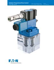
OFR-15/30 Series <strong>Filters</strong><br />
Flows to 115 L/min (30 USgpm) — Pressures to 40 bar (600 PSI)<br />
Features <strong>and</strong> Benefits<br />
• OFR-30 conforms to HF3<br />
specifications.<br />
• Two bowl length options.<br />
• Flows to 30 USgpm.<br />
• Visual indicator is st<strong>and</strong>ard.<br />
• Electrical indicator also available.<br />
• Bypass valve is st<strong>and</strong>ard.<br />
• Replacement elements available in<br />
C-Pak or single layer construction.<br />
• Accepts Eco-Pak coreless elements.<br />
(OFR30 only)<br />
Design Specifications<br />
Rated flow:<br />
OFR15 60 L/min (15 USgpm)<br />
OFR30 115 L/min (30 US gpm)<br />
Fluid Compatible with<br />
Compatibility: most petroleum<br />
oil, water glycol,<br />
oil-in-water <strong>and</strong> waterin-oil<br />
fluids.<br />
Temp range: -40°C to +107°C<br />
(- 40°F to +225°F)<br />
Pressure rating:<br />
Operating 40 bar (600 PSI)<br />
Element 100 PSI<br />
collapse rating:<br />
St<strong>and</strong>ard bypass valve setting:<br />
25 ± 4 PSI<br />
Material:<br />
Head Die cast aluminum<br />
Bowl Carbon steel<br />
Dry weight: (Approximate)<br />
OFR15 4,1 kg (9lbs)<br />
OFR30 5,4 kg (12lbs)<br />
General Data<br />
These filters are designed for use<br />
in the return lines of hydraulic systems.<br />
They remove particulate contaminants<br />
from the system fluid, thus improving<br />
performance <strong>and</strong> reliability of the<br />
system components while extending<br />
their service life. A bypass valve <strong>and</strong><br />
mechanical visual indicator are st<strong>and</strong>ard.<br />
Bypass Valve<br />
An internal relief valve parallels the<br />
element to limit the <strong>pressure</strong> drop<br />
across the element. The valve is<br />
set to open at 1.7 bar (25 PSI)<br />
as st<strong>and</strong>ard.<br />
Filter Elements<br />
These return line filters are o<strong>ff</strong>ered<br />
in C-Pak media <strong>and</strong> in single layer<br />
media.<br />
The C-Pak media has been designed<br />
to meet the requirements of <strong>Vickers</strong><br />
Systemic Contamination Control<br />
program <strong>and</strong> are available in 3, 5, 10<br />
<strong>and</strong> 20 micron (99% e<strong>ff</strong>icient) ratings.<br />
To learn more on this program,<br />
consult <strong>Vickers</strong> brochure. Replacement<br />
elements for C-Pak are ordered by<br />
model code.<br />
In some systems, the single layer<br />
media may o<strong>ff</strong>er an alternative. These<br />
are available in 15, 25 <strong>and</strong> 50 micron<br />
(99% e<strong>ff</strong>icient) ratings.<br />
Refer to the model code page for<br />
further information on filter elements<br />
<strong>and</strong> cleanliness ratings.<br />
Indicators<br />
Mechanical<br />
A rotary type indicator is mechanically<br />
associated with the bypass valve <strong>and</strong><br />
indicates the condition of this valve.<br />
Visible through the transparent<br />
windows in the protecting hood, the<br />
indicator will show green for a closed<br />
bypass valve <strong>and</strong> progressively show<br />
yellow for a warning that the element<br />
<strong>pressure</strong> drop is getting into the danger<br />
zone <strong>and</strong> red for an open bypass valve.<br />
By removing the protecting hood <strong>and</strong><br />
reassembling the rotary indicator 180<br />
on its stem, the indicator now provides<br />
a “memory” in that it rotates to the<br />
maximum opening of the bypass <strong>and</strong><br />
remains in this position until manually<br />
returned by rotation of the knurled<br />
projecting knob.<br />
Electrical<br />
A lever actuated electrical switch is<br />
mounted in the enclosure. An actuator<br />
mounted to the bypass valve<br />
depresses the switch just prior to the<br />
opening of the bypass valve to change<br />
the completion of the electrical switch<br />
circuit from the common <strong>and</strong> the<br />
normally closed terminals to the<br />
common <strong>and</strong> normally open terminals.<br />
The 1 /2 inch pipe tap is provided for<br />
connection to external conduit <strong>and</strong><br />
lengths of color coded wires are<br />
soldered to the switch terminals for<br />
connection to the external circuit<br />
through the wires in the conduit.<br />
The switch contacts are rated for 5<br />
amperes resistive loading up to<br />
250 Vac.<br />
16 EATON <strong>Low</strong> & <strong>High</strong> Pressure ProGuard <strong>Filters</strong> - OFR-15/30 Series in Line V-FF-MC-<strong>0001</strong>-E1 June 2002<br />
System Pressure<br />
The housing is suitable for greater than<br />
10 million <strong>pressure</strong> pulsations from 0 to<br />
600 PSI.<br />
Mounting Position<br />
Any mounting position is permitted.<br />
Vertical is preferred from a servicing<br />
st<strong>and</strong>point.<br />
Ports<br />
Straight thread ports accept the<br />
SAE fittings. Flange ports accept<br />
the 4-bolt SAE flange.<br />
Straight thread connections provide<br />
superior external leakage protection in<br />
applications having pulsating <strong>pressure</strong>s<br />
or system vibrations.<br />
Fluids <strong>and</strong> Seals<br />
Hydraulic oils, water glycols <strong>and</strong> waterin-oil<br />
emulsions can be filtered with the<br />
st<strong>and</strong>ard unit.<br />
Soluble oil in water fluids can also be<br />
filtered with the st<strong>and</strong>ard unit if the<br />
fluid pH does not exceed 8.5. A higher<br />
pH than this has an adverse e<strong>ff</strong>ect on<br />
the aluminum components.<br />
Synthetic fluids require special seals<br />
which can be obtained by prefixing the<br />
model number with “F3”.<br />
Refer to <strong>Vickers</strong> ‘‘Hydraulic Hints &<br />
Troubleshooting Guide’’ #694 for<br />
hydraulic fluid <strong>and</strong> temperature<br />
recommendations.
Performance Curves<br />
Filter Housing/Bypass Valve Flow Data<br />
Flow versus <strong>pressure</strong> drop:<br />
150 SUS (32 cSt) oil with specific gravity of ≤ 0.9<br />
(See page 5 for specific gravity corrections for <strong>pressure</strong> drop.)<br />
Housing Bypass Valve<br />
Pressure drop - bar (PSID)<br />
0.5<br />
(6) 0.4<br />
0.3<br />
(3) 0.2<br />
0.1<br />
OFR-15<br />
OFR-30<br />
0<br />
0 25 50 75 100 125 150<br />
(20) (33)<br />
Flow Rate - L/min (USgpm)<br />
Filter Element Flow Data<br />
mm (inch)<br />
The OFR-30 with 8" element meets HF3 specifications.<br />
Flow versus <strong>pressure</strong> drop:<br />
150 SUS (32 cSt) oil with specific gravity of ≤ 0.9<br />
(See page 6 for viscosity corrections for <strong>pressure</strong> drop.)<br />
6021 C-Pak<br />
203 (8) length<br />
Flow Rate - USgpm<br />
5 15 25 35 45 55 65 75<br />
Pressure drop - bar<br />
1,7<br />
1,4<br />
1,0<br />
0,7<br />
0,3<br />
0<br />
0<br />
C03<br />
05<br />
10<br />
20<br />
50 100 150 200 250<br />
Flow Rate - L/min<br />
5<br />
25<br />
20<br />
15<br />
10<br />
Pressure drop - PSID<br />
Pressure drop - bar (PSID)<br />
3.0<br />
(36) 2.5<br />
2.0<br />
(22) 1.5<br />
1.0<br />
.5<br />
1.75 bar cracking<br />
Single layer<br />
Single layer<br />
102 (4) length<br />
203 (8) length<br />
1.2<br />
(16) 1.1<br />
1.0<br />
0.8<br />
3M<br />
(15) 1.0<br />
3M<br />
(10) 0.7<br />
.75<br />
0.6<br />
0.4<br />
(4) 0.3<br />
0.1<br />
7M<br />
7G<br />
(7) 0.5<br />
.25<br />
7M<br />
7G<br />
0 50 100 150 200 250<br />
0<br />
0 100 200 300 400 500<br />
(26) (53)<br />
(53) (106)<br />
Flow Rate - L/min (USgpm) Flow Rate - L/min (USgpm)<br />
Pressure drop - bar (PSID)<br />
Pressure drop - bar (PSID)<br />
By-pass valve only<br />
blocked element<br />
50 100 150 200 250 300 350 400 450<br />
(40) (66) (92)<br />
Flow Rate - L/min (USgpm)<br />
EATON <strong>Low</strong> & <strong>High</strong> Pressure ProGuard <strong>Filters</strong> - OFR-15/30 Series in Line V-FF-MC-<strong>0001</strong>-E1 June 2002 17
Model Codes<br />
Filter <strong>and</strong> Element<br />
1<br />
Seals<br />
Blank - Buna-N<br />
F3 - Viton-A<br />
Viton is a registered trademark of E.I. DuPont<br />
2<br />
Filter type<br />
OFR - Oil filter return line<br />
3<br />
Flow capacity<br />
15 - 60 L/min (15 USgpm)<br />
30 - 115 L/min (30 USgpm)<br />
4<br />
Port options<br />
B - G1 (formerly 1” BSPF) thread<br />
F - 1” SAE 4-bolt flange Code 61<br />
S - 1.3125-12 UN SAE-16 straight<br />
thread 1” O.D. tube<br />
(F3) OFR 30 S C03 E 30 S50<br />
1 2 3 4 5 6 7 8<br />
Element options<br />
C-Pak construction*<br />
(For use with OFR-30 only)<br />
Fluid<br />
Cleanliness Element<br />
Code rating construction<br />
C03 16/14/12 C-Pak<br />
C05 18/16/14 C-Pak<br />
C10 20/18/15 C-Pak<br />
C20 22/19/16 C-Pak<br />
Single layer construction**<br />
Code Micron<br />
3M Beta 15 = 100<br />
7M Beta 25 = 100<br />
Blank Beta 50 = 100<br />
*NOTE: The C-Pak table assumes limited<br />
ingression <strong>and</strong> a single pass of pump flow<br />
through the element. For more detailed<br />
C-Pak element only V602 1 B 2 C 03<br />
(Meets HF3 Specifications)<br />
1 2 3 4 5 6<br />
1 Filter element<br />
V602<br />
2 Element collapse rating<br />
1 - 150 PSI <strong>Low</strong> Collapse<br />
3 Seals<br />
B - Buna-N<br />
V - Viton-A<br />
Viton is a registered trademark of E.I. DuPont<br />
Single layer media**<br />
replacement element kits<br />
(OFR-30 meets HF3 st<strong>and</strong>ard)<br />
**NOTE: Single layer construction<br />
elements are not assigned cleanliness<br />
codes <strong>and</strong> therefore cannot be applied<br />
toward <strong>Vickers</strong> Systemic Contamination<br />
Control Extended Warranty program.<br />
18 EATON <strong>Low</strong> & <strong>High</strong> Pressure ProGuard <strong>Filters</strong> - OFR-15/30 Series in Line V-FF-MC-<strong>0001</strong>-E1 June 2002<br />
5<br />
4 Element length<br />
mm (inch)<br />
2 - 203 (8) (HF3 length) (OFR30)<br />
5 Element construction<br />
C - C-Pak (grade 3, 5, 10, 20)<br />
assistance, please consult “The <strong>Vickers</strong><br />
Guide to Systemic Contamination Control”,<br />
or contact your local Eaton representative.<br />
**NOTE: Single layer construction elements<br />
are not assigned cleanliness codes <strong>and</strong><br />
therefore cannot be applied toward <strong>Vickers</strong><br />
Systemic Contamination Control Extended<br />
Warranty program.<br />
6 ∆P indicator options<br />
Blank - Mechanical 25 PSI<br />
E - Electrical 25 PSI<br />
7<br />
Design<br />
8 Special su<strong>ff</strong>ix<br />
S50 - Head sub-assembly only (No<br />
element, bowl or indicator)<br />
6 Fluid cleanliness ratings<br />
Fluid<br />
cleanliness Element<br />
Code rating construction<br />
C03 16/14/12 C-Pak<br />
C05 18/16/14 C-Pak<br />
C10 20/18/15 C-Pak<br />
C20 22/19/16 C-Pak<br />
Element Element Element Element<br />
Model Kit Code Micron Model Kit Code Micron<br />
OFR-15 737841 3M 15 F3-OFR-15 737844 7G 25<br />
737838 10M 50 737842 10M 50<br />
OFR-30 737849 3M 15 F3-OFR-30 737852 7G 25<br />
737847 7M 25 737850 10M 50<br />
737846 10M 50
Dimensions<br />
Mechanical Indicator<br />
mm (inch)<br />
Outlet port<br />
Electrical Indicator<br />
mm (inch)<br />
1 /2 NPTF thd.<br />
177,8 (7.00)<br />
min. lead<br />
extension<br />
Electrical Indicator<br />
Switch Circuit<br />
133,4 (5.25)<br />
66,5<br />
(2.62)<br />
Green<br />
Blue<br />
Red<br />
Black<br />
Inlet port<br />
66,5<br />
(2.62)<br />
131,8<br />
(5.19)<br />
53,8 (2.12)<br />
C<br />
NC<br />
NO<br />
Memory<br />
reset knob<br />
Visual indicator<br />
13,2<br />
(0.52)<br />
26,2<br />
(1.03)<br />
Drain plug<br />
Connections<br />
1.312-12 UN SAE<br />
1" G1 British<br />
pipe thread or<br />
1" SAE 4-bolt flg.<br />
Torque head<br />
bolts to<br />
25- 30 ft.lbs<br />
( 33- 41 Nm)<br />
98,6<br />
Dia.<br />
(3.88)<br />
52,3<br />
(2.06)<br />
26,2<br />
(1.03)<br />
180,8<br />
(7.12)<br />
OFR15<br />
273,1<br />
(10.75)<br />
OFR30<br />
3 /8-16 UNC-2B<br />
0.64 min. full thread<br />
2-places<br />
218,9<br />
(8.62)<br />
OFR-15<br />
311,2<br />
(12.25)<br />
OFR30<br />
269,7<br />
(10.62)<br />
OFR-15<br />
362,0<br />
(14.25)<br />
OFR30<br />
25,4 (1.00) Clearance<br />
for element removal<br />
87,4<br />
(3.44)<br />
99,3<br />
(3.91)<br />
267,5<br />
(10.53)<br />
OFR-15<br />
359,7<br />
(14.16)<br />
OFR-30<br />
EATON <strong>Low</strong> & <strong>High</strong> Pressure ProGuard <strong>Filters</strong> - OFR-15/30 Series in Line V-FF-MC-<strong>0001</strong>-E1 June 2002 19
OFR-60/120 Series <strong>Filters</strong><br />
Flows to 450 L/min (120 USgpm)- Pressures to 27 bar (400 PSI)<br />
Features <strong>and</strong> Benefits<br />
• Two bowl length options.<br />
• Visual indicator is st<strong>and</strong>ard.<br />
• Electrical indicator also available.<br />
• Bypass valve is st<strong>and</strong>ard.<br />
• Replacement elements available in<br />
C-Pak or single layer construction.<br />
• Accepts Eco-Pak coreless elements.<br />
Design Specifications<br />
Meets HF4 specifications<br />
Rated flow:<br />
OFR60 225 L/min (60 USgpm)<br />
OFR120 450 L/min (120 USgpm)<br />
Fluid Compatible with most<br />
compatibility: petroleum oil, water<br />
glycol, oil-in-water <strong>and</strong><br />
water-in-oil fluids.<br />
Temp range: -40°C to +107°C<br />
(-40°F to +225°F)<br />
Pressure rating:<br />
Operating 27 bar (400 PSI)<br />
St<strong>and</strong>ard bypass valve setting:<br />
25 ± 4 PSI<br />
Material:<br />
Head Die cast aluminum<br />
Bowl Carbon steel<br />
Dry weight: (Approximate)<br />
OFR60 6,8 kg (15 lbs)<br />
OFR120 9,5 kg (21 lbs)<br />
General Data<br />
These filters are designed for<br />
use in the return lines of hydraulic<br />
systems. They remove particulate<br />
contaminants from the system fluid,<br />
thus improving performance <strong>and</strong><br />
reliability of the system components<br />
while extending their service life. A<br />
bypass valve <strong>and</strong> mechanical visual<br />
indicator are st<strong>and</strong>ard.<br />
Bypass Valve<br />
An internal relief valve parallels the<br />
element to limit the <strong>pressure</strong> drop<br />
across the element. The valve is<br />
set to open at 1.7 bar (25 PSI)<br />
as st<strong>and</strong>ard.<br />
Filter Elements<br />
These return line filters are o<strong>ff</strong>ered in<br />
C-Pak media <strong>and</strong> in single layer media.<br />
The C-Pak media has been designed<br />
to meet the requirements of <strong>Vickers</strong><br />
Systemic Contamination Control<br />
program <strong>and</strong> are available in 3, 5, 10<br />
<strong>and</strong> 20 micron (99% e<strong>ff</strong>icient) ratings.<br />
To learn more on this program, consult<br />
<strong>Vickers</strong> brochure. Replacement<br />
elements for C-Pak are ordered by<br />
model code.<br />
In some systems, the single layer<br />
media may o<strong>ff</strong>er an alternative. These<br />
are available in 15, 25 <strong>and</strong> 50 micron<br />
(99% e<strong>ff</strong>icient) ratings.<br />
Refer to the model code page for<br />
further information on filter elements<br />
<strong>and</strong> cleanliness ratings.<br />
Indicators<br />
Mechanical<br />
A rotary type indicator is mechanically<br />
associated with the bypass valve <strong>and</strong><br />
indicates the condition of this valve.<br />
Visible through the transparent<br />
windows in the protecting hood, the<br />
indicator will show green for a closed<br />
bypass valve <strong>and</strong> progressively show<br />
yellow for a warning that the element<br />
<strong>pressure</strong> drop is getting into the danger<br />
zone <strong>and</strong> red for an open bypass valve.<br />
By removing the protecting hood <strong>and</strong><br />
reassembling the rotary indicator 180<br />
on its stem, the indicator now provides<br />
a “memory” in that it rotates to the<br />
maximum opening of the bypass <strong>and</strong><br />
remains in this position until manually<br />
returned by rotation of the knurled<br />
projecting knob.<br />
Electrical<br />
A lever actuated electrical switch is<br />
mounted in the enclosure. An<br />
actuator mounted to the bypass valve<br />
depresses the switch just prior to the<br />
opening of the bypass valve to change<br />
the completion of the electrical switch<br />
circuit from the common <strong>and</strong> the<br />
normally closed terminals to the<br />
common <strong>and</strong> normally open terminals.<br />
Cover can be rotated at 90 increments<br />
to four di<strong>ff</strong>erent positions. The 1 /2 inch<br />
pipe tap is provided for connection to<br />
external conduit <strong>and</strong> lengths of color<br />
20 EATON <strong>Low</strong> & <strong>High</strong> Pressure ProGuard <strong>Filters</strong> - OFR-60/120 Series in Line V-FF-MC-<strong>0001</strong>-E1 June 2002<br />
coded wires are soldered to the switch<br />
terminals for connection to the external<br />
circuit through the wires in the conduit.<br />
The switch contacts are rated for 5<br />
amperes resistive loading up to 250 Vac.<br />
Mounting Position<br />
Any mounting position is permitted.<br />
Vertical is preferred from a servicing<br />
st<strong>and</strong>point.<br />
Ports<br />
Straight thread ports accept the<br />
SAE fittings. Flange ports accept the<br />
4-bolt SAE flange.<br />
Straight thread connections provide<br />
superior external leakage protection in<br />
applications having pulsating <strong>pressure</strong>s<br />
or system vibrations.<br />
Fluids <strong>and</strong> Seals<br />
Hydraulic oils, water glycols <strong>and</strong> waterin-oil<br />
emulsions can be filtered with the<br />
st<strong>and</strong>ard unit.<br />
Soluble oil in water fluids can also be<br />
filtered with the st<strong>and</strong>ard unit if the<br />
fluid pH does not exceed 8.5. A higher<br />
pH than this has an adverse e<strong>ff</strong>ect on<br />
the aluminum components.<br />
Synthetic fluids require special seals<br />
which can be obtained by prefixing the<br />
model number with “F3”.<br />
Refer to <strong>Vickers</strong> ‘‘Hydraulic Hints &<br />
Troubleshooting Guide’’ #694 for<br />
hydraulic fluid <strong>and</strong> temperature<br />
recommendations.
Performance Curves<br />
Filter Housing/Bypass Valve Flow Data<br />
mm (inch)<br />
Flow versus <strong>pressure</strong> drop:<br />
150 SUS (32 cSt) oil with specific gravity of ≤ 0.9<br />
(See page 6 for viscosity corrections for <strong>pressure</strong> drop.)<br />
Housing Bypass Valve<br />
Pressure drop - bar (PSID)<br />
(15) 1.0<br />
.75<br />
(7) 0.5<br />
0.25<br />
(15) 1.0<br />
.75<br />
(7) 0.5<br />
OFR-120<br />
OFR-60<br />
0<br />
0 100 200 300 400 500<br />
(53) (106)<br />
Flow Rate - L/min (USgpm)<br />
Filter Element Flow Data<br />
mm (inch)<br />
Flow versus <strong>pressure</strong> drop:<br />
150 SUS (32 cSt) oil with specific gravity of ≤ 0.9<br />
(See page 6 for viscosity corrections for <strong>pressure</strong> drop.)<br />
4051 C-Pak<br />
229 (9) length<br />
Flow Rate - USgpm<br />
10 20 30 40 50<br />
Pressure drop - bar<br />
Single layer<br />
229 (9) length<br />
Pressure drop - bar (PSID)<br />
0,6<br />
0,4<br />
0,3<br />
0,1<br />
0<br />
0 50 100 150<br />
Flow Rate - L/min<br />
.25<br />
0<br />
0<br />
C03<br />
3M<br />
7M<br />
7G<br />
05<br />
10<br />
20<br />
8<br />
6<br />
4<br />
2<br />
Pressure drop - PSID<br />
Pressure drop - bar (PSID)<br />
(44) 3.0<br />
2.5<br />
(29) 2.0<br />
1.5<br />
(15) 1.0<br />
0.5<br />
0<br />
(15) 1.0<br />
(7) 0.5<br />
0<br />
Single layer<br />
457 (18) length<br />
By-pass valve only<br />
blocked element<br />
100 200 300 400<br />
(53)<br />
(106)<br />
Flow Rate - L/min (USgpm)<br />
4051 C-Pak<br />
457 (18) length<br />
Flow Rate - USgpm<br />
20<br />
40 60 80<br />
Pressure drop - bar<br />
0<br />
50 100 150 200 250<br />
0 100 200 300 400 500<br />
(26) (53)<br />
(53) (106)<br />
Flow Rate - L/min (USgpm) Flow Rate - L/min (USgpm)<br />
Pressure drop - bar (PSID)<br />
0,6<br />
0,4<br />
0,3<br />
0,1<br />
0<br />
.75<br />
.25<br />
EATON <strong>Low</strong> & <strong>High</strong> Pressure ProGuard <strong>Filters</strong> - OFR-60/120 Series in Line V-FF-MC-<strong>0001</strong>-E1 June 2002 21<br />
C03<br />
05<br />
10<br />
20<br />
3M<br />
7M<br />
7G<br />
100<br />
50 100 150 200 250 300 350<br />
Flow Rate - L/min<br />
8<br />
6<br />
4<br />
2<br />
Pressure drop - PSID
Model Codes<br />
Filter <strong>and</strong> Element (F3) OFR 60 S C03 E * 30 S50<br />
1<br />
Seals<br />
Blank - Buna-N<br />
F3 - Viton-A<br />
Viton is a registered trademark of E.I. DuPont<br />
2<br />
Filter type<br />
OFR - Oil filter return line<br />
3<br />
Flow capacity<br />
60 - 227 L/min (60 USgpm)<br />
120 - 454 L/min (120 USgpm)<br />
4<br />
Port options<br />
F -1 1 /2" SAE 4-bolt flange Code 61<br />
S - 1.875-12 UN SAE-24 straight<br />
thread for 1 1 /2" O.D. tube<br />
1 2 3 4 5 6 7 8 9<br />
Element options<br />
C-Pak construction*<br />
Fluid<br />
Cleanliness Element<br />
Code rating construction<br />
C03 16/14/12 C-Pak<br />
C05 18/16/14 C-Pak<br />
C10 20/18/15 C-Pak<br />
C20 22/19/16 C-Pak<br />
Single layer construction**<br />
Code Micron<br />
3M Beta 15 = 100<br />
7M Beta 25 = 100<br />
7G Beta 25 = 100<br />
Blank Beta 50 = 100<br />
*NOTE: The C-Pak table assumes limited<br />
ingression <strong>and</strong> a single pass of pump flow<br />
through the element. For more detailed<br />
assistance, please consult “The Systemic<br />
Approach to Contamination Control”, or<br />
contact your local Eaton representative.<br />
**NOTE: Single layer construction elements<br />
are not assigned cleanliness codes <strong>and</strong><br />
therefore cannot be applied toward <strong>Vickers</strong><br />
Systemic Contamination Control Extended<br />
Warranty program.<br />
C-Pak element only V405 1 B 3 C 03<br />
(Meets HF4 St<strong>and</strong>ard)<br />
1 2 3 4 5 6<br />
1 Filter element<br />
V405<br />
2 Element collapse rating<br />
1 - 150 PSI<br />
3 Seals<br />
B - Buna-N<br />
V - Viton-A<br />
Viton is a registered trademark of E.I. DuPont<br />
Single layer media**<br />
replacement element kits<br />
(Meets HF4 St<strong>and</strong>ard)<br />
**NOTE: Single layer construction<br />
elements are not assigned cleanliness<br />
codes <strong>and</strong> therefore cannot be applied<br />
toward <strong>Vickers</strong> Systemic Contamination<br />
Control Extended Warranty program.<br />
22 EATON <strong>Low</strong> & <strong>High</strong> Pressure ProGuard <strong>Filters</strong> - OFR-60/120 Series in Line V-FF-MC-<strong>0001</strong>-E1 June 2002<br />
5<br />
4 Element length<br />
mm (inch)<br />
3 - 229 (9) (Use in OFR-60)<br />
6 - 457 (18) (Use in OFR-120)<br />
5 Element construction<br />
C - C-Pak (grade 3, 5, 10, 20)<br />
6 ∆P indicator options<br />
Blank - Mechanical<br />
E - Electrical<br />
7 Bypass setting<br />
Blank - 25 PSI St<strong>and</strong>ard<br />
35 - 35 PSI<br />
50 - 50 PSI***<br />
8<br />
Design<br />
9 Special su<strong>ff</strong>ix<br />
(Omit if not required.)<br />
S50 - Filter housing minus element<br />
(Omit element options designation.)<br />
***CAUTION<br />
Applications involving high<br />
flow surges may cause<br />
• element collapse due to<br />
instantaneous <strong>pressure</strong><br />
spikes.<br />
6 Fluid cleanliness ratings<br />
Fluid<br />
Cleanliness Element<br />
Code rating construction<br />
C03 16/14/12 C-Pak<br />
C05 18/16/14 C-Pak<br />
C10 20/18/15 C-Pak<br />
C20 22/19/16 C-Pak<br />
*NOTE: Two 9 inch elements <strong>and</strong> a P-227567-01 reuseable connector can also<br />
be used in the OFR-120 housing. This arrangement meets HF4 specifications.<br />
Element Element Element Element<br />
Model Kit Code Micron Model Kit Code Micron<br />
OFR-60 737825 3M 15 F3-OFR-60 737829 3M 15<br />
737823 7M 25 737826 10M 50<br />
737822 10M 50<br />
OFR-120 737833 3M 15 F3-OFR-120 737834 10M 50<br />
737831 7M 25<br />
737830 10M 25
Dimensions<br />
hanical Mechanical Indicator Indicator<br />
inch)<br />
mm (inch)<br />
Memory reset 88,9<br />
.500-13UNC-2B thd.<br />
knob<br />
(3.50)<br />
.75 deep<br />
168,1 (6.62)<br />
Visual<br />
44,5 2 holes for mounting<br />
indicator<br />
(1.75)<br />
Outlet<br />
port<br />
1 /2 NPTF thd.<br />
177,8 (7.00) min.<br />
lead extension<br />
Electrical Indicator<br />
Switch Circuit<br />
84,1<br />
(3.31)<br />
Green<br />
Blue<br />
Red<br />
Black<br />
66,5<br />
(2.62)<br />
C<br />
Inlet<br />
port<br />
81,0<br />
(3.19)<br />
Note<br />
Plastic plug, part number 737365,<br />
is installed in the filter element to close<br />
the end of the element. When servicing element,<br />
remove <strong>and</strong> retain plastic plug 737365. Install<br />
new element with plastic<br />
plug on bottom.<br />
Electrical Indicator<br />
mm (inch)<br />
53,8 (2.12)<br />
NC<br />
NO<br />
162,1<br />
(6.38)<br />
Drain plug<br />
117,9<br />
Dia.<br />
(4.64)<br />
A port Conn.<br />
2 places<br />
Torque head bolts to<br />
50 ft.lbs (67,79 Nm) dry<br />
35 ft.lbs. (47,45 Nm)<br />
lubricated<br />
19,1 (0.75)<br />
320,5<br />
(12.62)<br />
OFR60<br />
93,0<br />
(3.66)<br />
550,9<br />
(21.69)<br />
OFR120<br />
25,4 (1.00) Clearance<br />
for element removal<br />
90,9<br />
(3.58)<br />
119,1<br />
(4.69)<br />
EATON <strong>Low</strong> & <strong>High</strong> Pressure ProGuard <strong>Filters</strong> - OFR-60/120 Series in Line V-FF-MC-<strong>0001</strong>-E1 June 2002 23
Manifolds<br />
Design Specifications<br />
Maximum flow capacity:<br />
946 L/min (250 USgpm)<br />
Pressure rating:<br />
Operating 27 bar (400 PSI)<br />
Temp range: -40°C to +107°C<br />
(-40°F to +225°F)<br />
Weight assembly:<br />
OFRM-12-20-10 2,7 kg (6.0 lbs)<br />
General Data<br />
This SAE flange manifold assembly is<br />
designed for use with OFR-60 <strong>and</strong><br />
OFR-120 large return line filters<br />
The manifold assembly includes the<br />
following:<br />
(2) Cast aluminum manifolds<br />
(4) Seals<br />
(8) Bolts<br />
Pressure Drop<br />
Pressure drop (∆P) across manifolds is<br />
approximately 2 PSI when passing 240<br />
gpm flow (Q) of 100 SUS fluid(s) having<br />
.865 flow rate.<br />
For any other flow rate (Q1), the<br />
<strong>pressure</strong> drop (∆P1) will be<br />
approximately:<br />
∆P1 = ∆P (Q1/Q) 2<br />
For any other specific gravity (G1), the<br />
<strong>pressure</strong> drop (∆P1) will be<br />
approximately:<br />
∆P1 = ∆P (G1/G) For any other viscosity(s), the <strong>pressure</strong><br />
drop (∆P) will change<br />
as follows:<br />
Other % of (∆P)<br />
viscosity(s) (Approx.)<br />
75 93<br />
150 111<br />
200 119<br />
250 126<br />
300 132<br />
350 137<br />
400 141<br />
Model Code<br />
1 Type<br />
OFRM - Oil filter, return line manifold<br />
Filter Connection Size<br />
12 - 11 2<br />
/2” SAE flange Code 61<br />
Dimensions<br />
mm (inch)<br />
96,0<br />
(3.78)<br />
35,6<br />
(1.40) Typ.<br />
50,8<br />
(2.00)<br />
25,4<br />
(1.00)<br />
50,8<br />
(2.00)<br />
25,4<br />
(1.00)<br />
60,5<br />
(2.38)<br />
17,8<br />
(.70) Typ.<br />
35,1<br />
(1.38) Typ.<br />
69,9<br />
(2.75) Typ.<br />
OFRM 12 20 10<br />
82,6<br />
(3.25)<br />
1 2 3 4<br />
327,2<br />
(12.88)<br />
24 EATON <strong>Low</strong> & <strong>High</strong> Pressure ProGuard <strong>Filters</strong> - OFR-60/120 Series in Line V-FF-MC-<strong>0001</strong>-E1 June 2002<br />
Line Connection Size<br />
20 - 21 3<br />
/2” SAE flange Code 61<br />
4 Design<br />
Subject to change. Installation<br />
dimensions remain the same for<br />
designs 10 through 19.<br />
41,1 (1.62)<br />
41,1 (1.62)<br />
82,6<br />
(3.25)<br />
50,8 (2.00)<br />
25,4 (1.00)<br />
.500-13 UNC-2B thd.<br />
1.00 deep 4 holes for<br />
mounting<br />
44,5<br />
(1.75)<br />
88,9 (3.50)<br />
1 1 / 2 SAE<br />
4-bolt flange<br />
connection<br />
2 1 / 2 SAE<br />
4-bolt flange<br />
connection<br />
.500-13 UNC-2B thd.<br />
4 holes each side
OFRS-15 Series <strong>Filters</strong><br />
Flows to 60 L/min (15 USgpm) — Pressures to 7 bar (100 PSI)<br />
Features <strong>and</strong> Benefits<br />
• Simple spin-on element design for<br />
easy maintenance.<br />
• Bypass valves prevent excessive<br />
<strong>pressure</strong> drop <strong>and</strong> accidental<br />
element collapse.<br />
• Two available ports for use as gauge<br />
<strong>and</strong>/or diagnostic ports.<br />
Design Specifications<br />
Rated flow: 57 L/min (15 USgpm)<br />
Fluid Compatible with most<br />
compatibility: petroleum oil, water<br />
glycol, oil-in-water <strong>and</strong><br />
water-in-oil fluids.<br />
Temp range: -40°C to +107°C<br />
(-40°F to +225°F)<br />
Pressure rating:<br />
Operating 7 bar (100 PSI)<br />
Material:<br />
Head Die cast aluminum<br />
Bowl Carbon steel<br />
Dry weight: (Approximate)<br />
1,0 kg (2.2 lbs.)<br />
General Data<br />
These filters are designed for use<br />
in the return lines of hydraulic systems.<br />
They remove particulate contaminants<br />
from the fluid, thus improving<br />
performance <strong>and</strong> reliability of the<br />
system components while extending<br />
their service life. R-Pak <strong>and</strong> single<br />
layer filter elements are available. The<br />
elements are of the disposable spin-on<br />
cartridge type for ease of maintenance.<br />
Integral Bypass Valve<br />
This bypass valve prevents excessive<br />
<strong>pressure</strong> drop <strong>and</strong> prevents the<br />
element from collapsing <strong>and</strong> releasing<br />
retained contaminants back into the<br />
hydraulic system. The valve starts to<br />
open when <strong>pressure</strong> drop across the<br />
element exceeds the valve setting due<br />
to flow surges, high viscosity oil, a<br />
clogged element, or a combination of<br />
these factors.<br />
Filter Elements<br />
These return line filters are o<strong>ff</strong>ered<br />
with two types of elements.<br />
When system requirements call for<br />
flow to 15 USgpm <strong>and</strong> <strong>pressure</strong> drops<br />
to 30 PSI, the 5 layer high <strong>pressure</strong><br />
R-Pak construction meets these<br />
dem<strong>and</strong>s. Replacement elements for<br />
R-Pak are ordered by model code.<br />
In applications where less dem<strong>and</strong>s<br />
are placed on the system, the single<br />
layer element may o<strong>ff</strong>er a more<br />
practical alternative. Replacement kits<br />
are available for servicing the single<br />
layer element.<br />
Refer to the model code page for<br />
further information on filter elements<br />
<strong>and</strong> cleanliness ratings.<br />
Gauge Ports <strong>and</strong><br />
Pressure Gauge<br />
An optional port in the filter head<br />
allows installation of a <strong>pressure</strong> gauge<br />
(P/N 736129) to indicate the element’s<br />
condition. This optional gauge is<br />
shipped uninstalled from the filter.<br />
Spin-On Cartridge<br />
The disposable cartridge screws onto<br />
the filter head <strong>and</strong> should be h<strong>and</strong><br />
tightened per instructions printed on<br />
the cartridge.<br />
Refer to the model code page for<br />
further information on filter cartridges<br />
<strong>and</strong> cleanliness ratings.<br />
Mounting Position<br />
Any mounting position is permitted.<br />
Vertical is preferred from a servicing<br />
st<strong>and</strong>point.<br />
Fluids <strong>and</strong> Seals<br />
These filters are suitable for petroleum<br />
based, oil-water emulsions, high water<br />
base, <strong>and</strong> most water glycol fluids.<br />
EATON <strong>Low</strong> & <strong>High</strong> Pressure ProGuard <strong>Filters</strong> - OFRS-15 Series Spin-on V-FF-MC-<strong>0001</strong>-E1 June 2002 25
Performance Curves<br />
Filter Assembly <strong>and</strong> Element Flow Data<br />
mm (inch)<br />
Flow versus <strong>pressure</strong> drop:<br />
150 SUS (32 cSt) oil with specific gravity of ≤ 0.9<br />
(See page 5 for specific gravity corrections for <strong>pressure</strong> drop.)<br />
Single Layer with 0.7 bar (10 psi) Bypass Valve<br />
Pressure drop - bar<br />
3,0<br />
2,0<br />
1,0<br />
5<br />
0 20 40 60 80 100 120 140 160 180<br />
Flow Rate - L/min<br />
V0191 R-Pak Filter Element<br />
147 (5.8) length<br />
Pressure drop - bar<br />
0,6<br />
0,5<br />
0,4<br />
0,2<br />
0,1<br />
0<br />
0<br />
5 10 15<br />
R03<br />
R05<br />
R10<br />
20<br />
10<br />
26 EATON <strong>Low</strong> & <strong>High</strong> Pressure ProGuard <strong>Filters</strong> - OFRS-15 Series Spin-on V-FF-MC-<strong>0001</strong>-E1 June 2002<br />
8<br />
6<br />
4<br />
2<br />
Single Layer with 1.75 bar (25 psi) Bypass Valve<br />
Flow Rate - USgpm Flow Rate - USgpm<br />
10 15 20 25 30<br />
Filter assembly with<br />
25 micron element<br />
Filter assembly with<br />
40 micron element<br />
78%<br />
94%<br />
35 40 45 50<br />
0.7 bar bypass 40<br />
valve only<br />
(Blocked element)<br />
30<br />
50%<br />
61%<br />
20<br />
59%<br />
71%<br />
10<br />
3,0<br />
2,5<br />
2,0<br />
1,5<br />
1,0<br />
0,5<br />
5 10 15<br />
1.75 bar bypass<br />
valve only<br />
(Blocked element)<br />
Filter assembly with<br />
25 micron element<br />
Filter assembly with<br />
40 micron element<br />
Note:<br />
The % shown is the % of flow which<br />
passes thru a clean element with 150 SUS<br />
fluid. The remaining flow will pass thru the<br />
bypass valve without filtration.<br />
Flow Rate - USgpm<br />
10 20 30 40 50 60 70<br />
Flow Rate - L/min<br />
Pressure drop - PSID<br />
Pressure drop - PSID<br />
Pressure drop - bar<br />
0 10 20 30 40 50 60 70<br />
V0191 R-Pak Filter Element<br />
203 (8) length<br />
Pressure drop - bar<br />
0,6<br />
0,5<br />
0,4<br />
0,2<br />
0,1<br />
Flow Rate - L/min<br />
Flow Rate - USgpm<br />
10 20 30<br />
R03<br />
R05<br />
0<br />
0 20 40 60 80 100 120 140<br />
Flow Rate - L/min<br />
R10<br />
20<br />
40<br />
35<br />
30<br />
25<br />
20<br />
15<br />
10<br />
5<br />
40<br />
10<br />
8<br />
6<br />
4<br />
2<br />
Pressure drop - PSID Pressure drop - PSID
Model Codes<br />
Filter <strong>and</strong> Element<br />
OFRS 15 S 2R03 P B E 10 10 S50<br />
1<br />
Series designation<br />
OFRS - Oil Filter, Return line,<br />
Spin-on<br />
2<br />
Flow rating<br />
15 -15 USgpm (57 L/min)<br />
3<br />
Port type<br />
B - G1 (formerly 1” BSPF) thd.<br />
P - 1” NPTF<br />
S - 1.312-12 UN SAE-16 straight<br />
thd. for 1” OD tube<br />
4 Element type<br />
Canister<br />
Code Length<br />
mm (inch)<br />
Fluid Cleanliness<br />
1R03 147 (5.8) 16/14/12<br />
1R05 147 (5.8) 18/16/14<br />
1R10 147 (5.8) 20/18/15<br />
2R03 203 (8.0) 16/14/12<br />
2R05 203 (8.0) 18/16/14<br />
2R10 203 (8.0) 20/18/15<br />
1 Series designation<br />
V019 - Filter element for use with<br />
OFRS15/OFRS25 – series filters<br />
(R–Pak construction only)<br />
2 Element collapse rating<br />
1 - 150 PSI<br />
3 Seal material<br />
B - Buna–N<br />
4 Element length<br />
mm (inch)<br />
1 - 147 (5.8)<br />
2 - 203 (8.0)<br />
5 Element construction<br />
R - R–Pak<br />
1 2 3 4 5 6 7 8 9 10<br />
The table assumes limited<br />
ingression/single pass of pump<br />
flow through element. For detailed<br />
assistance, see <strong>Vickers</strong> Guide to<br />
Systemic Contamination Control<br />
or contact your local Eaton<br />
representative.<br />
Code Filtration Element<br />
Rating Construction<br />
25M 40 micron Single layer<br />
Blank 25 micron Single layer<br />
NOTE: Because single layer elements are<br />
not assigned Fluid Cleanliness Codes,<br />
they are not eligible for <strong>Vickers</strong> Systemic<br />
Contamination Control Extended Warranty<br />
program.<br />
5 Pressure gauge option<br />
P - Pressure gauge 0-120 PSI (0-8 bar)<br />
Blank - Omit if not required.<br />
R-Pak element V019 1 B 2 R 03<br />
1 2 3 4 5 6<br />
6 Element type<br />
Fluid<br />
Cleanliness Element<br />
Code rating construction<br />
03 16/14/12 R–Pak<br />
05 18/16/14 R–Pak<br />
10 20/18/15 R–Pak<br />
The table assumes limited<br />
ingression/single pass of pump<br />
flow through element. For detailed<br />
assistance, see “The <strong>Vickers</strong> Guide<br />
to Systemic Contamination Control”<br />
or contact your local Eaton<br />
representative.<br />
Inlet gauge port location<br />
( 1 6<br />
/8” NPTF)<br />
B - Location B<br />
Blank - Omit if not required.<br />
Outlet gauge port location<br />
( 1 7<br />
/8” NPTF)<br />
E - Location E<br />
Blank - Omit if not required.<br />
8 Bypass valve<br />
10 - Bypass valve set at 10 PSI<br />
Blank - Bypass valve set at 25 PSI<br />
9 Design number<br />
Subject to change. Dimensions remain<br />
the same for designs 10 through 19.<br />
10 Special su<strong>ff</strong>ix<br />
(Omit if not required.)<br />
S50 - Filter housing minus element<br />
(Omit element options designation.)<br />
Single Layer Media Element<br />
Replacement element Micron Rating Nominal Rating<br />
573082 25 B25 = 100 10 micron<br />
573083 40 B40 = 100 25 micron<br />
NOTE: Because single layer elements are not assigned Fluid Cleanliness Codes, they are<br />
not eligible for <strong>Vickers</strong> Systemic Contamination Control Extended Warranty program.<br />
EATON <strong>Low</strong> & <strong>High</strong> Pressure ProGuard <strong>Filters</strong> - OFRS-15 Series Spin-on V-FF-MC-<strong>0001</strong>-E1 June 2002 27
Dimensions<br />
Filter Housing<br />
mm (inch)<br />
B Pressure<br />
gauge<br />
connection<br />
47,8<br />
(1.88)<br />
23,9<br />
(0.94)<br />
11,2<br />
(0.44)<br />
7,87R<br />
(0.31R)<br />
Optional<br />
<strong>pressure</strong><br />
gauge<br />
Approx.<br />
55,9<br />
(2.20)<br />
Inlet<br />
port<br />
26,9<br />
(1.06)<br />
12,7<br />
(0.50)<br />
Clearance required for<br />
removal of cartridge<br />
98,8<br />
(3.89)<br />
11,2<br />
(0.44)<br />
26,9<br />
(1.06)<br />
49,3<br />
(1.94)<br />
.375-16 UNC-2B thd.<br />
19,1 (0.75) min. full thd.<br />
2 holes for mounting<br />
Mounting screw torque<br />
20-27 Nm (15-20 ft-lb)<br />
3,05R Typ.<br />
(0.12R)<br />
E Pressure gauge connection<br />
1 /8" NPTF pipe thd.<br />
2 locations (see Model Code)<br />
27,2 (1.07)<br />
13,5<br />
(0.53)<br />
9,53/9,78R<br />
(0.375/0.385R) Typ.<br />
Outlet<br />
port<br />
Std.<br />
194,6<br />
(7.66)<br />
Long<br />
250,4<br />
(9.86)<br />
Std.<br />
170,2<br />
(6.70)<br />
Long<br />
226,1<br />
(8.9)<br />
28 EATON <strong>Low</strong> & <strong>High</strong> Pressure ProGuard <strong>Filters</strong> - OFRS-15 Series Spin-on V-FF-MC-<strong>0001</strong>-E1 June 2002<br />
24,4<br />
(0.96)<br />
97,5<br />
(3.84)<br />
Max.<br />
44,4<br />
(1.75)<br />
Hex. - both<br />
ends
OFRS-25 Series <strong>Filters</strong><br />
Flows to 95 L/min (25 USgpm) — Pressures to 7 bar (100 PSI)<br />
Features <strong>and</strong> Benefits<br />
• Simple spin-on element design for<br />
easy maintenance.<br />
• Bypass valve prevents excessive<br />
<strong>pressure</strong> drop <strong>and</strong> accidental<br />
element collapse.<br />
• Six available ports for use as gauge<br />
<strong>and</strong>/or diagnostic ports.<br />
Design Specifications<br />
Rated flow: 95 L/min (25 USgpm)<br />
Fluid Suitable for use<br />
compatibility: with petroleum<br />
based, oil-water<br />
emulsions, high<br />
water based <strong>and</strong><br />
most water-glycol<br />
fluids.<br />
Temp range: -40°C to +107°C<br />
(-40°F to +225°F)<br />
Pressure rating:<br />
Operating 7 bar (100 PSI)<br />
Material:<br />
Head Die cast aluminum<br />
Canister Carbon steel<br />
Dry weight: (Approximate)<br />
0,9 kg (2.0 lbs)<br />
General Data<br />
These filters are designed for use in<br />
the return lines of hydraulic systems.<br />
They remove particulate contaminants<br />
from the fluid, thus improving<br />
performance <strong>and</strong> reliability of the<br />
system components while extending<br />
their service life. R-Pak <strong>and</strong> single layer<br />
filter elements are available. The<br />
elements are of the disposable spin-on<br />
cartridge type for ease of maintenance.<br />
Integral Bypass Valve<br />
This bypass valve prevents excessive<br />
<strong>pressure</strong> drop <strong>and</strong> prevents the<br />
element from collapsing <strong>and</strong> releasing<br />
retained contaminants back into the<br />
hydraulic system. The valve starts to<br />
open when <strong>pressure</strong> drop across the<br />
element exceeds the valve setting due<br />
to flow surges, high viscosity oil, a<br />
clogged element,<br />
or a combination of these factors.<br />
Filter Elements<br />
These return line filters are o<strong>ff</strong>ered with<br />
two types of elements.<br />
When system requirements call for<br />
flow to 25 USgpm <strong>and</strong> <strong>pressure</strong> drops<br />
to 30 PSI, the 5 layer high <strong>pressure</strong><br />
R-Pak construction meets these<br />
dem<strong>and</strong>s. Replacement elements for<br />
R-Pak are ordered by model code.<br />
In applications where less dem<strong>and</strong>s are<br />
placed on the system, the single layer<br />
element may o<strong>ff</strong>er a more practical<br />
alternative. Replacement kits are<br />
available for servicing the single<br />
layer element.<br />
Refer to the model code page for<br />
further information on filter elements<br />
<strong>and</strong> cleanliness ratings.<br />
Gauge Ports <strong>and</strong><br />
Pressure Gauge<br />
An optional port in the filter head<br />
allows installation of a <strong>pressure</strong> gauge<br />
(P/N 736129) to indicate the element’s<br />
condition. This optional gauge is<br />
shipped uninstalled from the filter.<br />
Spin-On Cartridge<br />
The disposable cartridge screws onto<br />
the filter head <strong>and</strong> should be h<strong>and</strong><br />
tightened per instructions printed on<br />
the cartridge.<br />
Refer to the model code page for<br />
further information on filter cartridges<br />
<strong>and</strong> cleanliness ratings.<br />
Mounting Position<br />
Any mounting position is permitted.<br />
Vertical is preferred from a servicing<br />
st<strong>and</strong>point.<br />
Fluids <strong>and</strong> Seals<br />
These filters are suitable for petroleum<br />
based, oil-water emulsions, high water<br />
base, <strong>and</strong> most water glycol fluids.<br />
EATON <strong>Low</strong> & <strong>High</strong> Pressure ProGuard <strong>Filters</strong> - OFRS-25 Series Spin-on V-FF-MC-<strong>0001</strong>-E1 June 2002 29
Performance Curves<br />
Filter Assembly <strong>and</strong> Element Flow Data<br />
mm (inch)<br />
Flow versus <strong>pressure</strong> drop:<br />
150 SUS (32 cSt) oil with specific gravity of ≤ 0.9<br />
(See page 5 for specific gravity corrections <strong>and</strong> page 6 for viscosity corrections for <strong>pressure</strong> drop.)<br />
Single Layer with 1.75 bar (25 psi) Bypass Valve<br />
Pressure drop - bar<br />
3,5<br />
3,0<br />
2,5<br />
2,0<br />
1,5<br />
1,0<br />
0,5<br />
Flow Rate - USgpm<br />
5 10 15 20 25 30<br />
50<br />
Filter assembly<br />
with 25 micron<br />
element<br />
1.75 bar bypass<br />
valve only<br />
(blocked element)<br />
Filter assembly<br />
with 40 micron<br />
element<br />
0 20 40 60 80 100<br />
V0191 R-Pak Filter Element<br />
147 (5.8) length<br />
Pressure drop - bar<br />
0,6<br />
0,5<br />
0,4<br />
0,2<br />
0,1<br />
Flow Rate - L/min<br />
30 EATON <strong>Low</strong> & <strong>High</strong> Pressure ProGuard <strong>Filters</strong> - OFRS-25 Series Spin-on V-FF-MC-<strong>0001</strong>-E1 June 2002<br />
40<br />
30<br />
20<br />
10<br />
Flow Rate - USgpm Flow Rate - USgpm<br />
5 10 15 20<br />
10<br />
0,6<br />
10 20 30 40<br />
10<br />
R03<br />
R05<br />
8<br />
6<br />
0,5<br />
0,4<br />
R03<br />
R05<br />
8<br />
6<br />
R10<br />
4<br />
2<br />
0,2<br />
0,1<br />
R10<br />
4<br />
2<br />
0<br />
0 10 20 30 40 50 60 70<br />
Flow Rate - L/min<br />
Pressure drop - PSID<br />
Pressure drop - PSID<br />
V0191 R-Pak Filter Element<br />
203 (8.0) length<br />
Pressure drop - bar<br />
0<br />
0 2040 60<br />
Flow Rate - L/min<br />
80 100 120 140<br />
Pressure drop - PSID
Model Codes<br />
1<br />
Series designation<br />
OFRS - Oil Filter, Return line,<br />
Spin-on<br />
2<br />
Flow rating<br />
25 -25 USgpm (95 L/min)<br />
3 Port type<br />
B - G1 (formerly 1” BSPF) thd.<br />
F - 1” SAE- 4-bolt flange Code 61<br />
P - 1” NPTF<br />
S - 1.312-12 UN SAE-16 straight<br />
thd. for 1” OD tube<br />
Single Layer Media Element<br />
Replacement element Micron<br />
573082 25<br />
573083 40<br />
1 Series designation<br />
V019 - Filter element for use with<br />
OFRS15/OFRS25 – series filters<br />
(R–Pak construction only)<br />
2 Element collapse rating<br />
1 - 150 PSI<br />
OFRS 25 S 1R03 P A D 0 10 S50<br />
1 2 3 4 5 6 7 8 9 10<br />
4 Element type<br />
Canister Fluid Cleanliness<br />
Code Length<br />
mm (inch)<br />
Code<br />
1R03 147 (5.8) 16/14/12<br />
1R05 147 (5.8) 18/16/14<br />
1R10 147 (5.8) 20/18/15<br />
2R03 203 (8.0) 16/14/12<br />
2R05 203 (8.0) 18/16/14<br />
2R10 203 (8.0) 20/18/15<br />
The table assumes limited<br />
ingression/single pass of pump<br />
flow through element. For detailed<br />
assistance, see <strong>Vickers</strong> Guide to<br />
Systemic Contamination Control<br />
or contact your local Eaton<br />
representative.<br />
Code Filtration Element<br />
Rating Construction<br />
25M 40 micron Single layer<br />
Blank 25 micron Single layer<br />
NOTE: Because single layer elements are<br />
not assigned Fluid Cleanliness Codes,<br />
they are not eligible for <strong>Vickers</strong> Systemic<br />
Contamination Control Extended Warranty<br />
program.<br />
Rating Nominal Rating<br />
B25 = 100 10 micron<br />
B40 = 100 25 micron<br />
R-Pak element V019 1 B 1 R 03<br />
1 2 3 4 5 6<br />
3 Seal material<br />
B - Buna–N<br />
4 Element length<br />
mm (inch)<br />
1 - 147 (5.8)<br />
2 - 203 (8.0)<br />
5 Element construction<br />
R - R–Pak<br />
Pressure gauge option<br />
P - Pressure gauge 0-120 PSI (0-8 bar)<br />
Blank - Omit if not required.<br />
Inlet gauge port location<br />
( 1 5<br />
6<br />
/8” NPTF)<br />
A - Location A<br />
B - Location B<br />
C - Location C<br />
Blank - Omit if not required.<br />
Outlet gauge port location<br />
( 1 7<br />
/8” NPTF)<br />
D - Location D<br />
E - Location E<br />
F - Location F<br />
Blank - Omit if not required.<br />
NOTE: Gauges cannot be mounted side by<br />
side. If inlet <strong>and</strong> outlet gauges are required,<br />
specify non-adjacent ports such as A <strong>and</strong> E.<br />
8 Bypass valve<br />
0 - Non-bypass<br />
Blank - Bypass valve set at 25 PSI<br />
9 Design number<br />
Subject to change. Dimensions remain<br />
the same for designs 10 through 19.<br />
10 Special su<strong>ff</strong>ix<br />
(Omit if not required.)<br />
S50 - Filter housing minus element<br />
(Omit element options designation.)<br />
6 Element type<br />
Fluid<br />
Cleanliness Element<br />
Code Code Construction<br />
03 16/14/12 R–Pak<br />
05 18/16/14 R–Pak<br />
10 20/18/15 R–Pak<br />
The table assumes limited<br />
ingression/single pass of pump<br />
flow through element. For detailed<br />
assistance, see “The <strong>Vickers</strong> Guide<br />
to Systemic Contamination Control”<br />
or contact your local Eaton<br />
representative.<br />
EATON <strong>Low</strong> & <strong>High</strong> Pressure ProGuard <strong>Filters</strong> - OFRS-25 Series Spin-on V-FF-MC-<strong>0001</strong>-E1 June 2002 31
Dimensions<br />
Filter Housing<br />
mm (inch)<br />
Approx.<br />
66,7<br />
(2.62)<br />
56,4<br />
(2.22)<br />
Inlet<br />
port<br />
Optional<br />
<strong>pressure</strong><br />
gauge<br />
26,9<br />
(1.06)<br />
C<br />
B<br />
A<br />
12,7<br />
(0.50)<br />
Clearance required for<br />
removal of cartridge<br />
53,8<br />
(2.12)<br />
103,1<br />
(4.06)<br />
51,6<br />
(2.03)<br />
.375-16 UNC-2B thd.<br />
15,7 (0.62) min. full thd.<br />
4 holes for mounting<br />
Mounting screw torque 20-27 Nm (15-20 ft-lb)<br />
FPressure gauge connection<br />
1 /8" NPTF pipe thd.<br />
6 locations (see Model Code)<br />
Outlet<br />
port<br />
47,6 (1.88)<br />
40,4<br />
(1.59)<br />
81,0<br />
(3.19)<br />
23,9<br />
(0.94)<br />
23,9<br />
(0.94)<br />
Std.<br />
194,1<br />
(7.64)<br />
Long<br />
250,4<br />
(9.86)<br />
Std.<br />
170,2<br />
(6.70)<br />
Long<br />
226,1<br />
(8.9)<br />
32 EATON <strong>Low</strong> & <strong>High</strong> Pressure ProGuard <strong>Filters</strong> - OFRS-25 Series Spin-on V-FF-MC-<strong>0001</strong>-E1 June 2002<br />
D<br />
E<br />
.375-16 UNC-2B thd.<br />
16,3 (0.64) min. full thd.<br />
4 holes each end only when<br />
F port type is specified.<br />
Use <strong>Vickers</strong> FL1-8-08P-10 or<br />
FL1-8-08W-10 flanges.<br />
52,3<br />
(2.06)<br />
97,5<br />
(3.84)<br />
26,2<br />
(1.03) 13,1<br />
(0,52)<br />
26,2<br />
(1.03)
OFRS-60 Series <strong>Filters</strong><br />
Flows to 227 L/min (60 USgpm) — Pressures to 7 bar (100 PSI)<br />
Features <strong>and</strong> Benefits<br />
• Available with <strong>Vickers</strong> proprietary<br />
R-Pak media.<br />
• Simple spin-on element design for<br />
easy maintenance.<br />
• Optional bypass valves prevent<br />
excessive <strong>pressure</strong> drop <strong>and</strong><br />
accidental element collapse.<br />
• Six available ports for use as gauge<br />
<strong>and</strong>/or diagnostic ports.<br />
• H20-Pro Water Removing Element<br />
available.<br />
Design Specifications<br />
Rated flow: 227 L/min (60 USgpm)<br />
Fluid Compatible with most<br />
compatibility: petroleum oil, water<br />
glycol, oil-in-water <strong>and</strong><br />
water-in-oil fluids.<br />
Temp range: -40°C to +107°C<br />
(-40F to +225F)<br />
Pressure rating:<br />
Operating 7 bar (100 PSI)<br />
Material:<br />
Head Die cast aluminum<br />
Bowl Carbon steel<br />
Dry weight: (Approximate)<br />
Bowl length 1 4,4 kg (5.0 lbs)<br />
Bowl length 2 5,6 kg (6.5 lbs)<br />
General Data<br />
These filters are designed for use in<br />
the return lines of hydraulic systems.<br />
They remove particulate contaminants<br />
from the fluid, thus improving<br />
performance <strong>and</strong> reliability of the<br />
system components while extending<br />
their service life. R-Pak <strong>and</strong> single<br />
layer filter elements are available. The<br />
elements are of the disposable spin-on<br />
cartridge type for ease of maintenance.<br />
Integral Bypass Valve<br />
This option prevents excessive <strong>pressure</strong><br />
drop <strong>and</strong> prevents the element from<br />
collapsing <strong>and</strong> releasing retained<br />
contaminants back into the hydraulic<br />
system. The valve starts to open when<br />
<strong>pressure</strong> drop across the element<br />
exceeds 25 PSI due to flow surges, high<br />
viscosity oil, a clogged element, or a<br />
combination of these factors.<br />
Gauge Ports/<br />
Pressure Gauge<br />
Optional ports in the filter head allow<br />
installation of a <strong>pressure</strong> gauge (part<br />
736129) to indicate the element’s<br />
condition. The optional gauge is<br />
shipped uninstalled from the filter.<br />
Filter Elements<br />
These return line filters are o<strong>ff</strong>ered with<br />
two types of elements.<br />
When system requirements call for<br />
flow to 60 USgpm <strong>and</strong> <strong>pressure</strong> drops<br />
to 30 PSI the high <strong>pressure</strong> R-Pak<br />
construction meets these dem<strong>and</strong>s.<br />
Replacement elements for R-Pak are<br />
ordered by model code.<br />
In applications where less dem<strong>and</strong>s are<br />
placed on the system the single layer<br />
Pressure drop bar (PSID)<br />
(6) 0.4<br />
0.3<br />
(3) 0.2<br />
0.1<br />
0<br />
0 75 150 225<br />
(20) (40)<br />
Flow Rate - L/min (USgpm)<br />
Filter Element<br />
Flow versus <strong>pressure</strong> drop: 150 SUS (32 cSt) oil with specific gravity of ≤ 0.9<br />
(See page 5 for specific gravity corrections for <strong>pressure</strong> drop.)<br />
R-Pak Elements<br />
Single Layer Elements<br />
0211 R-Pak 184mm (7.2")<br />
Pressure drop - bar (PSID)<br />
Pressure drop - bar (PSID)<br />
(9) 0,6<br />
(6) 0,4<br />
(3) 0,2<br />
R03<br />
05<br />
10<br />
20<br />
0<br />
0 25 50 75 100 125 150<br />
(7) (20) (33)<br />
Flow Rate - L/min (USgpm)<br />
0211 R-Pak 286mm (11.3")<br />
(9) 0,6<br />
(6) 0,4<br />
(3) 0,2<br />
0<br />
R03<br />
50 100 150 200 250 300<br />
(13) (40) (67)<br />
Flow Rate - L/min (USgpm)<br />
05<br />
10<br />
20<br />
element may o<strong>ff</strong>er a more practical<br />
alter-native. Replacement kits are<br />
available for servicing the single layer<br />
element. Refer to the model code page<br />
for further information on filter<br />
elements <strong>and</strong> cleanliness ratings.<br />
Spin-On Cartridge<br />
The disposable cartridge screws onto<br />
the filter head <strong>and</strong> should be tightened<br />
per instructions on the cartridge.<br />
Mounting Position<br />
Any mounting position is permitted.<br />
Vertical is preferred for servicing.<br />
Fluids <strong>and</strong> Seals<br />
These filters are suitable for petroleum<br />
based, oil-water emulsions, high water<br />
base, <strong>and</strong> most water glycol fluids.<br />
Filter Housing Flow Data<br />
Flow versus <strong>pressure</strong> drop: 150 SUS (32 cSt) oil with specific gravity of ≤ 0.9<br />
(See page 5 for specific gravity corrections for <strong>pressure</strong> drop.)<br />
Pressure drop bar (PSID)<br />
3.0 Bypass valve only<br />
(blocked element)<br />
(36) 2.5<br />
2.0<br />
Filter assembly with<br />
25 micron element<br />
(22) 1.5<br />
0.5<br />
Filter assembly with<br />
15 micron element<br />
Filter assembly with 60 micron element<br />
50 100 150 200<br />
(26)<br />
(53)<br />
Flow Rate - L/min (USgpm)<br />
H 20-Pro Water Removing<br />
Element W0211B2W10 287MM<br />
3.0<br />
(36) 2.5<br />
2.0<br />
(22) 1.5<br />
0.5<br />
Pressure drop bar (PSID)<br />
50 100<br />
(26)<br />
150 200<br />
(53)<br />
Flow Rate - L/min (USgpm)<br />
EATON <strong>Low</strong> & <strong>High</strong> Pressure ProGuard <strong>Filters</strong> - OFRS-60 Series Spin-on V-FF-MC-<strong>0001</strong>-E1 June 2002 33
Dimensions<br />
OFRS-60<br />
Body or Line Mounting<br />
mm (inch)<br />
Approx.<br />
85,7<br />
(3.38)<br />
A<br />
B<br />
56,4<br />
(2.22)<br />
Inlet<br />
port<br />
Optional<br />
<strong>pressure</strong><br />
gauge<br />
C<br />
53,8<br />
(2.12)<br />
41,3<br />
(1.62)<br />
122,9<br />
(2.84)<br />
33,3 (1.31)<br />
Clearance required for<br />
removal of cartridge<br />
144,5<br />
(5.69)<br />
26,9<br />
(1.06)<br />
53,8<br />
(2.12)<br />
40,4<br />
(1.59)<br />
81,0<br />
(3.19)<br />
.5000-13 UNC-2B thd.<br />
0.875 min. full thd.<br />
4 holes each end only when<br />
F port type is specified.<br />
Use <strong>Vickers</strong> FL1-12-12P-10 or<br />
FL1-12-12W-10 flanges.<br />
Outlet<br />
port<br />
.375-16 UNC-2B thd.<br />
0.75 min. full thd.<br />
2 holes for mounting<br />
Mounting screw torque 15-20 lb. ft<br />
(20-27 Nm)<br />
F Pressure gauge connection<br />
1 /8" NPTF pipe thd.<br />
6 locations (see Model Code)<br />
34 EATON <strong>Low</strong> & <strong>High</strong> Pressure ProGuard <strong>Filters</strong> - OFRS-60 Series Spin-on V-FF-MC-<strong>0001</strong>-E1 June 2002<br />
D<br />
E<br />
Element<br />
Dimension<br />
G H<br />
St<strong>and</strong>ard 211,1 242,8<br />
(8.31) (9.56)<br />
Long 312,7 344,4<br />
(12.31) (13.56)<br />
NOTE<br />
A, B, C Inlet gauge port locations<br />
D, E, F Outlet gauge port locations<br />
H<br />
G<br />
31,7<br />
(1.25)<br />
69,9<br />
(2.75)<br />
34,8<br />
(1.37)<br />
128,5<br />
(5.06)<br />
136,5<br />
(5.38)<br />
17,9<br />
(0.70)<br />
35,6<br />
(1.41)
Dimensions<br />
OFRS-60-2<br />
Manifold Mounting<br />
Outlet Port Connection<br />
mm (inch)<br />
F Pressure gauge<br />
connection 1 / 8" NPTF<br />
pipe thd. 6 locations<br />
(see Model Code)<br />
E<br />
D<br />
81,0<br />
(3.19)<br />
Inlet<br />
port<br />
Optional<br />
<strong>pressure</strong><br />
gauge<br />
40,4<br />
(1.59)<br />
56,4<br />
(2.22)<br />
26,9<br />
(1.06)<br />
53,8<br />
(2.12)<br />
33,3 (1.31)<br />
Clearance required for<br />
removal of cartridge<br />
144,5<br />
(5.69)<br />
53,8<br />
(2.12)<br />
41,3<br />
(1.62)<br />
122,9<br />
(2.84)<br />
.375-16 UNC-2B thd.<br />
0.75 min. full thd.<br />
2 holes for mounting<br />
Mounting screw torque 15-20 lb. ft<br />
(20-27 Nm)<br />
D<br />
B<br />
Approx.<br />
85,7<br />
(3.38)<br />
139,7<br />
(5.50)<br />
Outlet<br />
port<br />
A<br />
38,1<br />
(1.50)<br />
.5000-13 UNC-2B thd.<br />
0.875 min. full thd.<br />
4 holes each end only when<br />
F port type is specified.<br />
Use <strong>Vickers</strong> FL1-12-12P-10 or<br />
FL1-12-12W-10 flanges.<br />
Seal groove to accept A-225 seal<br />
5,38 (2.12)OD x 47,7 (1.88)<br />
ID x 3,05 (0.12) C/S<br />
10,3 (0.41)<br />
Thru holes for<br />
mounting<br />
31,7<br />
(1.25)<br />
211,1<br />
(8.31*)<br />
Note<br />
A, B, C Inlet gauge port locations<br />
D, E, F Outlet gauge port locations<br />
Pressure gauge in locations D <strong>and</strong> F<br />
will require additional fitting to clear<br />
mounting bolt hex nuts. Use Aeroquip<br />
No. 2040-2-25 or equivalent.<br />
69,8<br />
(2.75) 34,7<br />
120,7<br />
(4.75)<br />
60,2<br />
(2.37)<br />
(1.37)<br />
17,8<br />
(0.70)<br />
35,7<br />
(1.41)<br />
17,8<br />
(0.70)<br />
128,5<br />
(5.06)<br />
136,5<br />
(5.38)<br />
* Add 101,6 (4.00) for long 10mm element.<br />
35,7<br />
(1.41)<br />
EATON <strong>Low</strong> & <strong>High</strong> Pressure ProGuard <strong>Filters</strong> - OFRS-60 Series Spin-on V-FF-MC-<strong>0001</strong>-E1 June 2002 35
Model Codes<br />
Filter <strong>and</strong> Element<br />
OFRS 60 * S 1R03 PAD * 10 S50<br />
1<br />
Series designation<br />
OFRS - Oil Filter, Return line, Spin-on<br />
2<br />
Flow rating<br />
60 - 60 USgpm (227 L/min)<br />
3<br />
Mounting<br />
2 - Reservoir mount flange (outlet)<br />
Blank - Body or line mounting<br />
4<br />
Port type<br />
B - G1 1 /2 (formerly 1 /2" BSPF) thd.<br />
F - 1 1 /2" SAE 4-bolt flange<br />
P - 1 1 /2" NPTF<br />
S - 1.875-12 UN SAE-24 straight thd.<br />
for 1 1 /2" OD tube<br />
1 2 3 4 5 6 7 8 9 10 11<br />
5 Element type<br />
Canister Fluid Cleanliness<br />
Code Length<br />
mm (inch)<br />
Code<br />
1R03 - 184 (7) 16/14/12<br />
1R05 - 184 (7) 18/16/14<br />
1R10 - 184 (7) 20/18/15<br />
1R20 - 184 (7) 22/19/16<br />
2R03 - 286 (11) 16/14/12<br />
2R05 - 286 (11) 18/16/14<br />
2R10 - 286 (11) 20/18/15<br />
2R20 - 286 (11) 22/19/16<br />
2W10 - 286 (11) Water Removal<br />
The table assumes limited ingression/<br />
single pass of pump flow through<br />
element. For detailed assistance,<br />
see “The <strong>Vickers</strong> Guide to Systemic<br />
Contamination Control” or contact your<br />
local Eaton representative.<br />
Other element options:<br />
Filtration Element<br />
Code rating construction<br />
3M - 15 micron Single layer<br />
25M - 60 micron Single layer<br />
Blank - 25 micron Single layer<br />
NOTE: Because single layer elements are<br />
not assigned Fluid Cleanliness Codes,<br />
they are not eligible for <strong>Vickers</strong> Systemic<br />
Contamination Control Extended Warranty<br />
program.<br />
6 Pressure gauge option<br />
P - Pressure gauge<br />
Blank -Omit if not required<br />
36 EATON <strong>Low</strong> & <strong>High</strong> Pressure ProGuard <strong>Filters</strong> - OFRS-60 Series Spin-on V-FF-MC-<strong>0001</strong>-E1 June 2002<br />
Inlet gauge port location<br />
( 1 7<br />
/8” NPTF)<br />
A - Location A<br />
B - Location B<br />
C - Location C<br />
Blank – Omit if not required<br />
Outlet gauge port location<br />
( 1 8<br />
/8” NPTF)<br />
D - Location D<br />
E - Location E<br />
F - Location F<br />
Blank - Omit if not required<br />
NOTE: Gauges cannot be mounted side by<br />
side. If inlet <strong>and</strong> outlet gauges are required,<br />
specify non-adjacent ports such as A <strong>and</strong> E.<br />
9 Bypass valve<br />
0 - No bypass valve<br />
Blank - Bypass valve set at 25 PSI<br />
10 Design number<br />
Subject to change. Dimensions remain<br />
the same for designs 10 through 19.<br />
11 Special feature su<strong>ff</strong>ix<br />
S14 - Long 25 micron element<br />
S50 - Housing without element<br />
(omit code for element type)<br />
Blank - Omit if not required
Model Codes<br />
R-Pak Element Only<br />
1<br />
Series designation<br />
V021 - Filter element for use with<br />
H021, H022, H023 <strong>and</strong><br />
OFRS-60 series filters<br />
(R-Pak construction only)<br />
W021 - Water Removal element for<br />
use with H021, H022, H023<br />
<strong>and</strong> OFRS-60 series filters<br />
2 Element collapse rating<br />
1 - 150 PSI <strong>Low</strong> Pressure<br />
VO21 1 B 1 R 03<br />
1 2 3 4 5 6<br />
3 Seal material<br />
B - Buna-N<br />
Single Layer Media Element Only<br />
4 Canister length<br />
mm (inch)<br />
1 - 184 (7)<br />
2 - 286 (11)<br />
NOTE: Water removal element only available<br />
in length 2.<br />
5 Element construction<br />
R - R-Pak (grade 3,5,10,20)<br />
W -W-Pak (Water Removal) (grade 10)<br />
Replacement<br />
Element Number Micron Rating Nominal Rating<br />
941190 Std. Length 15 B15 = 100 3 micron<br />
941107 Std. Length 25 B25 = 100 10 micron<br />
926388 Long Length 25 B25 = 100 10 micron<br />
941191 Std. Length 60 B60 = 100 25 micron<br />
NOTE<br />
Because single layer elements are not<br />
assigned Fluid Cleanliness Codes, they<br />
are not eligible for <strong>Vickers</strong> Systemic<br />
Contamination Control Extended<br />
Warranty program.<br />
6 Fluid cleanliness rating<br />
Fluid<br />
Cleanliness Element<br />
Code Code construction<br />
03 16/14/12 R-Pak<br />
05 18/16/14 R-Pak<br />
10 20/18/15 R-Pak, W-Pak<br />
20 22/19/16 R-Pak<br />
The table assumes limited<br />
ingression/single pass of pump<br />
flow through element. For detailed<br />
assistance, see “The <strong>Vickers</strong> Guide<br />
to Systemic Contamination Control”<br />
or contact your local Eaton<br />
representative.<br />
EATON <strong>Low</strong> & <strong>High</strong> Pressure ProGuard <strong>Filters</strong> - OFRS-60 Series Spin-on V-FF-MC-<strong>0001</strong>-E1 June 2002 37
HS22 Series <strong>Filters</strong><br />
Flows to 450 L/min (120 USgpm) — Pressures to 14 bar (200 PSI)<br />
Features <strong>and</strong> Benefits<br />
• Designed to comply with ANSI<br />
specifications <strong>and</strong> ISO cleanliness<br />
st<strong>and</strong>ards.<br />
• Dual flow path design maximizes<br />
flow capability <strong>and</strong> service life.<br />
• Spin-on element make servicing fast<br />
<strong>and</strong> easy<br />
• <strong>High</strong> e<strong>ff</strong>iciency replacement<br />
elements in st<strong>and</strong>ard configurations<br />
(R-Pak) to meet Target Cleanliness<br />
Levels<br />
• Water removal element (W-Pak)<br />
available<br />
Design Specifications<br />
Rated flow:<br />
Length 1 227 L/min (60 USgpm)<br />
Length 2 454 L/min (120 USgpm)<br />
Housing & Compatible with<br />
Element most petroleum oil,<br />
Compatibility: water glycol, oil-in-water<br />
<strong>and</strong> water-in-oil fluids.<br />
Temp range: -32°C to +107°C<br />
(-25°F to +225°F)<br />
Pressure rating:<br />
Operating 14 bar (200 PSI)<br />
Material:<br />
Head Aluminum<br />
Dry weight: (Approximate)<br />
Length 1 7.3 kg (16 lbs)<br />
Length 2 8.6 kg (19 lbs)<br />
Filter Assembly Model Code<br />
1 Filter Series<br />
HS22<br />
38 EATON <strong>Low</strong> & <strong>High</strong> Pressure ProGuard <strong>Filters</strong> - HS22 V-FF-MC-<strong>0001</strong>-E1 June 2002<br />
HS22 1 SD 3 2 N B 2 R 05<br />
1 2 3 4 5<br />
2 Element Collapse Rating<br />
1 - 150 PSID <strong>Low</strong> Pressure<br />
Port options<br />
BD - G11 /2 to ISO 228<br />
ME - 11 /2" SAE 4 bolt Flange Code 61<br />
(M12 x 1.75)<br />
SD - 1.875 - 12 UN sae-24 str. Thd<br />
(11 /2 tube)<br />
FE - 11 3<br />
/2" SAE 4 bolt Flange Code 61<br />
(UNC)<br />
4 Valve options<br />
3 - 25 PSI bypass<br />
4 - 50 PSI bypass<br />
5 Indicator options<br />
1 - No indicator<br />
2 - 0 - 200 PSI gauge<br />
4 - 0 - 60 PSI gauge<br />
6 Receptical<br />
N - None<br />
7 Seal material<br />
B - Buna-N<br />
6 7 8 9 10<br />
8 Canister Assembly<br />
length length<br />
1 - 184mm (7”) 253mm (10”)<br />
2 - 286mm (11”) 355mm (14”)<br />
S50 - Head Sub-Assembly Only<br />
(no element or gauge)<br />
9 Element construction<br />
R - St<strong>and</strong>ard construction<br />
(3, 5, 10, 20 Micron)<br />
W -Water removal<br />
(10 Micron only)<br />
10 Fluid cleanliness rating<br />
Target fluid<br />
Code cleanliness level<br />
03 16/14/12 or better<br />
05 18/16/14 or better<br />
10 20/18/15 or better<br />
20 22/19/16 or better<br />
The table assumes limited<br />
ingression/single pass of pump<br />
flow through element. For detailed<br />
assistance, see “The Systemic<br />
Approach to Contamination Control”<br />
or contact your local Eaton<br />
representative.
Dimensions<br />
HS22 Series Housing<br />
mm (inch)<br />
Housing<br />
1,2<br />
(15) 1,0<br />
Pressure drop - bar (PSID)<br />
0,8<br />
(9) 0,6<br />
0,4<br />
(3) 0,2<br />
60<br />
(2.36)<br />
128.3<br />
(5.05)<br />
Filter Housing/Bypass Valve Flow Data<br />
0 100 200 300 400<br />
(26)<br />
(79)<br />
Flow Rate - L/min (USgpm)<br />
286.0<br />
(11.26)<br />
171.0<br />
(6.73)<br />
286<br />
(11.26)<br />
Flow versus <strong>pressure</strong> drop:<br />
150 SUS (32 cSt) oil with specific gravity of ≤ 0.9<br />
(See page 5 for specific gravity corrections for <strong>pressure</strong> drop.)<br />
Bypass Valve<br />
Pressure drop - bar (PSID)<br />
(73) 5,0<br />
4,0<br />
(44) 3,0<br />
2,0<br />
(15) 1,0<br />
146<br />
(5.75)<br />
165.5<br />
(6.52)<br />
Mounting Holes<br />
3/8"-16 - 4 Places<br />
35.5<br />
(1.40)<br />
40.0<br />
(1.57)<br />
50 PSID Valve<br />
Refer to<br />
Model Code<br />
25 PSID Valve<br />
0 100 200 300 400<br />
(26)<br />
(79)<br />
Flow Rate - L/min (USgpm)<br />
EATON <strong>Low</strong> & <strong>High</strong> Pressure ProGuard <strong>Filters</strong> - HS22 V-FF-MC-<strong>0001</strong>-E1 June 2002 39<br />
65<br />
45
021 Series Replacement Filter Elements<br />
Element Model Code<br />
V021 1 B 2 R 05<br />
1<br />
Filter element<br />
V021 - For use with HS22 <strong>and</strong><br />
OFR-S60 series filters<br />
W021 - Water Removal Element for<br />
use with HS22 <strong>and</strong> OFR-S60<br />
series filters<br />
2 Element collapse rating<br />
1 - 150 PSI<br />
286<br />
(11.30)<br />
1 2 3 4 5 6<br />
Design Specifications<br />
Rated flow: 227 L/min (60 USgpm)<br />
cannister length 1<br />
184<br />
(7.30)<br />
454 L/min (120 USgpm)<br />
cannister length 2<br />
Fluid Compatible with most<br />
Compatibility: petroleum oil, water<br />
glycol, oil-in-water <strong>and</strong><br />
water-in-oil fluids.<br />
Construction: R-Pak, W-Pak<br />
Temp range: -32°C to +107°C<br />
(-25°F to +225°F)<br />
Dimensions<br />
mm (inch)<br />
1 1 / 2"-16UN thd.<br />
126<br />
(5.00)<br />
3 Seal material<br />
B - Buna-N<br />
4 Canister length<br />
mm (inch)<br />
1 - 184 (7)<br />
2 - 286 (11)<br />
NOTE: Water removal element only available<br />
in length 2.<br />
5 Element construction<br />
R - R-Pak (grade 3, 5, 10, 20)<br />
W - W-Pak, Water Removal (grade 10)<br />
Filter Element Flow Data<br />
mm (inch)<br />
Flow versus <strong>pressure</strong> drop:<br />
150 SUS (32 cSt) oil with specific gravity of ≤ 0.9<br />
(See page 6 for viscosity corrections for <strong>pressure</strong> drop.)<br />
Pressure drop bar (PSID)<br />
Pressure drop bar (PSID)<br />
R-Pak Elements<br />
0211 R-Pak element 184mm (7.2")<br />
(6) 0.4<br />
0.3<br />
R03<br />
R05<br />
(3) 0.2<br />
0.1<br />
R10<br />
R20<br />
0<br />
0 25 50 75 100 125 150<br />
(7) (20) (33)<br />
Flow Rate - L/min (USgpm)<br />
0211 R-Pak element 286mm (11.3")<br />
(6) 0.4<br />
0.3<br />
(3) 0.2<br />
0.1<br />
R03<br />
R05<br />
R10<br />
R20<br />
0<br />
0 50 100 150 200 250 300<br />
(13) (40) (66)<br />
Flow Rate - L/min (USgpm)<br />
40 EATON <strong>Low</strong> & <strong>High</strong> Pressure ProGuard <strong>Filters</strong> - HS22 V-FF-MC-<strong>0001</strong>-E1 June 2002<br />
6 Fluid cleanliness ratings<br />
Fluid<br />
Cleanliness Element<br />
Code Code construction<br />
03 16/14/12 R-Pak<br />
05 18/16/14 R-Pak<br />
10 20/18/15 R-Pak, W-Pak<br />
20 22/19/16 R-Pak<br />
The table assumes limited<br />
ingression/single pass of pump<br />
flow through element. For detailed<br />
assistance, see “The <strong>Vickers</strong> Guide<br />
to Systemic Contamination Control”<br />
or contact your local Eaton<br />
representative.<br />
H 20-Pro Water Removing<br />
Element W0211B2W10 286 (11) length<br />
Pressure drop - bar (PSID)<br />
(25) 1,7<br />
1,4<br />
(15) 1,0<br />
0,7<br />
(5) 0,3<br />
50 100 150 200<br />
(13) (40)<br />
Flow Rate - L/min (USgpm)<br />
Note<br />
The HS22 assembly uses two<br />
filter elements in parallel. The<br />
<strong>pressure</strong> drop information is<br />
for two elements in parallel.
OF3 Series Inlet Strainers<br />
Flows to 379 L/min (100 USgpm)<br />
Features <strong>and</strong> Benefits<br />
• Stainless steel elements have 149<br />
micron (100 mesh) screen to protect<br />
hydraulic pumps from solid<br />
contaminants.<br />
• Available flow rates to 379 L/min<br />
(100 USgpm). <strong>High</strong>er rates can be<br />
achieved by using multiple strainers.<br />
• Bypass valve available to prevent<br />
system shutdown.<br />
• Element media is pleated for long life.<br />
• Elements can be cleaned <strong>and</strong> reused.<br />
Design Specifications<br />
Rated flow:<br />
OF3-08 38 L/min (10 USgpm)<br />
OF3-10 76 L/min (20 USgpm)<br />
OF3-12 114 L/min (30 USgpm)<br />
OF3-16 189 L/min (50 USgpm)<br />
OF3-20 284 L/min (75 USgpm)<br />
OF3-24 379 L/min (100 USgpm)<br />
Fluid compatibility:<br />
These strainers are compatible with<br />
all commonly used hydraulic fluids,<br />
including phosphate esters <strong>and</strong><br />
water based fluids.<br />
Temp range: -40°C to +107°C<br />
(-40°F to +225°F)<br />
Filtration: Unit is supplied with<br />
149 micron (100 mesh)<br />
wire cloth element.<br />
Material:<br />
Head Nylon<br />
Element Pleated stainless steel<br />
Dry weight: (Approximate)<br />
OF3-08 0,3 kg (0.7 lbs)<br />
OF3-10 0,4 kg (1.0 lbs)<br />
OF3-12 0,6 kg (1.4 lbs)<br />
OF3-16 0,8 kg (1.8 lbs)<br />
OF3-20 1,0 kg (2.3 lbs)<br />
OF3-24 1,4 kg (3.0 lbs)<br />
General Data<br />
These <strong>Vickers</strong> inlet strainers protect<br />
hydraulic pumps <strong>and</strong> control systems<br />
from solid contaminants. They should<br />
be used as immersion suction strainers<br />
on pump inlet lines.<br />
Bypass Valve<br />
An available integral relief valve<br />
parallels the element <strong>and</strong> is preset to<br />
open at a 3 PSI <strong>pressure</strong> drop across<br />
the element. Element bypassing can be<br />
caused by excess flow rates, high fluid<br />
viscosity, dirt-loaded elements, or a<br />
combination of these.<br />
Model Code<br />
1<br />
Model Series<br />
OF3 - Inlet strainers<br />
Port Size (NPTF)<br />
08 -1”<br />
10 -11 /4"<br />
12 -11 /2"<br />
16 -2”<br />
20 -21 2<br />
/2"<br />
24 -3”<br />
OF3 12 3RV 10<br />
Element Selection<br />
The size <strong>and</strong> number of elements<br />
selected should be based on the<br />
maximum flow ratings listed on this<br />
page. The ratings are conservative, <strong>and</strong><br />
a change in fluid viscosity should not<br />
significantly a<strong>ff</strong>ect capacity.<br />
Cleaning<br />
The strainer elements should be<br />
cleaned periodically. Remove the<br />
elements from the reservoir, wash<br />
thoroughly in a suitable solvent, <strong>and</strong><br />
blow dry with air from inside to outside.<br />
1 2 3 4<br />
3 Bypass Valve<br />
3RV - 3 PSI di<strong>ff</strong>erential opening<br />
<strong>pressure</strong><br />
Blank - Omit if not required<br />
4 Design number<br />
Subject to change. Dimensions remain<br />
the same for designs 10 through 19.<br />
EATON <strong>Low</strong> & <strong>High</strong> Pressure ProGuard <strong>Filters</strong> - OF3 Series Inlet Strainers V-FF-MC-<strong>0001</strong>-E1 June 2002 41
Installation Dimensions<br />
Inlet Strainer<br />
mm (inch)<br />
Minimum Screen Area<br />
Model Series cm 2 (in 2 ) A (NPTF pipe thread) B C ±3,2 (±0.125)<br />
OF3-08 710 (110) 1” 67,8 (2.67) 135,9 (5.35)<br />
OF3-10 1032 (160) 11 /4” 88,1 (3.47) 174,0 (6.85)<br />
OF3-12 2194 (340) 11 /2” 101,6 (4.00) 250,2 (9.85)<br />
OF3-16 2194 (340) 2” 101,6 (4.00) 250,2 (9.85)<br />
OF3-20 2581 (400) 21 /2” 131,3 (5.17) 256,5 (10.10)<br />
OF3-24 3226 (500) 3” 131,3 (5.17) 299,2 (11.78)<br />
Typical Installations<br />
42 EATON <strong>Low</strong> & <strong>High</strong> Pressure ProGuard <strong>Filters</strong> - OF3 Series Inlet Strainers V-FF-MC-<strong>0001</strong>-E1 June 2002<br />
C<br />
Oil level<br />
Pump intake<br />
connection<br />
Access opening should be provided so<br />
strainers can be removed for cleaning<br />
without draining fluid from tank.<br />
A<br />
Pipe joints submerged<br />
B<br />
Disconnect pipe union<br />
to remove strainers
10F, 50F <strong>and</strong> 100F Series — Indicating Inlet Strainers<br />
Flows to 700 L/min (185 USgpm) — Pressures to<br />
0,3 bar (5 PSI) vacuum to 20 bar (300 PSI) positive<br />
Features <strong>and</strong> Benefits<br />
• Stainless elements have 149 micron<br />
(100 mesh) screen to protect pumps<br />
from solid contaminants.<br />
• Available flows to 700 L/min (185<br />
USgpm) on <strong>pressure</strong> inlets <strong>and</strong> 530<br />
L/min (140 USgpm) on vacuum<br />
inlets.<br />
• St<strong>and</strong>ard integral air bleed feature<br />
prevents formation of large bubbles.<br />
This provides faster priming of<br />
pumps at startup <strong>and</strong> prevents pump<br />
damage.<br />
• Housing can be adapted to h<strong>and</strong>le<br />
most hydraulic fluids.<br />
• Large, easy to read, st<strong>and</strong>ard visual<br />
indicator (or optional electrical<br />
indicator) informs operator when<br />
element needs to be cleaned.<br />
• Elements can be cleaned <strong>and</strong><br />
reused.<br />
• St<strong>and</strong>ard bypass valve protects<br />
against pump damage.<br />
Design Specifications<br />
Rated flow: See table<br />
Temp range: -40°C to +107°C<br />
(-40°F to +225°F)<br />
Pressure rating:<br />
10F <strong>and</strong> 50F: 0,3 bar (5 PSI)<br />
vacuum to 3 bar<br />
(50 PSID) positive<br />
100F: 20 bar (300 PSI)<br />
Filtration: Filter is supplied with<br />
149 micron (100<br />
mesh) wire cloth<br />
element.<br />
Fluid <strong>and</strong> seals:<br />
St<strong>and</strong>ard model is compatible with<br />
most petroleum oil, water glycol,<br />
<strong>and</strong> water-in-oil fluids. Optional seals<br />
s<strong>and</strong> coatings are available for use<br />
in phosphate esters <strong>and</strong> oil-water<br />
emulsions. See fluids <strong>and</strong> seals note<br />
in Model Code.<br />
Material:<br />
Cover Die cast aluminum<br />
Housing Cast aluminum<br />
Dry weight: (Approximate)<br />
10F: 2,5 kg (5.5 lb)<br />
50F: 5,7 kg (12.5 lb)<br />
100F: 16,3 kg (36.0 lb)<br />
Maximum Flow Ratings<br />
This table presents recommendations<br />
for use in both pressurized inlet<br />
systems <strong>and</strong> the more common<br />
vacuum inlet systems. The e<strong>ff</strong>ects of<br />
fluid viscosity, specific gravity, <strong>and</strong> fluid<br />
flow rate on the pump inlet system<br />
(including the filter) have been taken<br />
into consideration. Even with a bypass<br />
condition in e<strong>ff</strong>ect due to element dirt<br />
loading, a margin of pump protection is<br />
still a<strong>ff</strong>orded.<br />
Vacuum Inlet* Pressurized Inlet**<br />
Normal Special Normal Special<br />
Service† Service†† Service† Service††<br />
Model L/min L/min L/min L/min<br />
Series (USgpm) (USgpm) (USgpm) (USgpm)<br />
10FA 45 (12) 30 (8) 61 (16) 42 (11)<br />
50FB 106 (28) 76 (20) 140 (37) 95 (25)<br />
50FC 178 (47) 125 (33) 257 (68) 167 (44)<br />
50FD 254 (67) 178 (47) 329 (87) 238 (63)<br />
100FE 367 (97) 284 (75) 492 (130) 367 (97)<br />
100FF 530 (140) 367 (97) 700 (185) 492 (130)<br />
* 0,3 bar (5 PSI) vacuum to 0 bar (0 PSI)<br />
** 0 bar (0 PSI) to 50 bar (3.5 PSI)<br />
† For use with petroleum oil up to 48 cSt (225 SUS) with less than<br />
457mm (18”) lift on vacuum applications.<br />
†† For use with petroleum oils above 48 cSt (225 SUS) <strong>and</strong> fire resistant fluids.<br />
EATON <strong>Low</strong> & <strong>High</strong> Pressure ProGuard <strong>Filters</strong> - 10F, 50F & 100F Series Indicating Inlet Series V-FF-MC-<strong>0001</strong>-E1 June 2002 43
Indicating Inlet Strainers<br />
General Data<br />
These units have been designed for use<br />
in the intake lines of hydraulic pumps to<br />
a<strong>ff</strong>ord a degree of protection from<br />
contaminants to the pump <strong>and</strong> other<br />
components in the hydraulic system.<br />
Bypass Valve<br />
An integral relief valve parallels the<br />
element <strong>and</strong> is preset to open at<br />
a 2 PSI (st<strong>and</strong>ard) or 3 PSI (optional)<br />
<strong>pressure</strong> drop across the element.<br />
Element bypassing can be caused by<br />
excess flow rates, high fluid viscosity,<br />
dirt-loaded elements, or a combination<br />
of these.<br />
Air Bleed<br />
These strainers include a st<strong>and</strong>ard<br />
integral air bleed. It provides faster<br />
pump priming on startup <strong>and</strong> limits the<br />
agglomeration of small air bubbles into<br />
larger ones. Large air bubbles are<br />
detrimental to pump operation.<br />
The unit may be mounted in any<br />
position desired. To ensure proper<br />
operation of the air bleed feature,<br />
however, the inlet port must be<br />
pointed down.<br />
Magnets<br />
Magnets are available as an accessory<br />
<strong>and</strong> are installed in the filter on the<br />
outside of the element. They act to<br />
attract <strong>and</strong> retain ferrous particles of all<br />
sizes, some of which could be small<br />
enough to pass through the element<br />
mesh <strong>and</strong> into the pump if no magnets<br />
were present.<br />
Indicators<br />
Visual<br />
A highly visible mechanical indicator is<br />
linked to the bypass valve. The indicator<br />
shows green when the bypass valve is<br />
closed <strong>and</strong> progressively more yellow<br />
as a warning when the element<br />
<strong>pressure</strong> drop gets into the danger<br />
zone. Red indicates an open bypass<br />
valve. The indicator will also<br />
automatically show red, (bypass<br />
condition) if the unit is accidentally<br />
operated without an element.<br />
The visual indicator can also be<br />
reassembled to provide a “memory”<br />
function. If the protecting hood is<br />
removed <strong>and</strong> the rotary indicator turned<br />
180° on its stem, the unit will indicate<br />
the maximum opening of the bypass<br />
<strong>and</strong> remain in that position until reset<br />
by rotating the knurled projecting knob.<br />
Electrical<br />
A lever-actuated electric switch is<br />
mounted in the indicator enclosure. The<br />
switch is depressed by a cam mounted<br />
to the bypass valve just prior to the<br />
opening of the valve. This changes<br />
the completion of the electrical switch<br />
circuit from the common <strong>and</strong> the<br />
normally closed terminals to the<br />
common <strong>and</strong> normally open terminals.<br />
Switch actuation will also occur when<br />
the unit is accidentally operated<br />
without an element.<br />
Switch Circuit<br />
GREEN<br />
44 EATON <strong>Low</strong> & <strong>High</strong> Pressure ProGuard <strong>Filters</strong> - 10F, 50F & 100F Series Indicating Inlet Series V-FF-MC-<strong>0001</strong>-E1 June 2002<br />
BLUE<br />
RED<br />
BLACK<br />
A 1 /2” pipe tap is provided for<br />
connecting a conduit, <strong>and</strong> lengths of<br />
color coded wires are soldered to the<br />
switch terminals for connecting to the<br />
external circuit through the conduit<br />
wires. The switch contacts are rated<br />
for 5 amps resistive loading up to<br />
250V AC.<br />
C<br />
NC<br />
NO
Model Code<br />
1<br />
Fluid Compatibility*<br />
F3 - Special seals<br />
F6 - For oil-in-water emulsions<br />
Blank – Omit if not required.<br />
* Use of synthetic, fire-resistant fluids<br />
requires filter with special seals. Add<br />
prefix F3 to model number when<br />
phosphate esters or their blends are to<br />
be used. Oil-in-water emulsions require<br />
corrosion protection of aluminum parts.<br />
Add prefix F6 when using such fluids.<br />
Water glycol, water-in-oil emulsions,<br />
<strong>and</strong> petroleum oil fluids may be used<br />
with st<strong>and</strong>ard seals.<br />
2 Package Size<br />
10 - 10 size<br />
50 - 50 size<br />
100 - 100 size<br />
3 Model Series<br />
F - Indicating type inlet filter<br />
(F3) 100 F E 1 SF E 3 M 12/20<br />
1 2 3 4 5<br />
6 7 8 9 10<br />
Port Size<br />
A - 1” (10F)<br />
B - 11 /2” (50F)<br />
C - 2” (50F)<br />
D - 21 /2”” (50F)<br />
E - 3” (100F)<br />
F - 31 4<br />
/2” (100F)<br />
5 Mean Filtration Rating<br />
1 - 149 micron (100 mesh)<br />
6 Port Type<br />
B - G1 (formerly 1” BSPF) thd.<br />
(10F only)<br />
F - 4-bolt SAE flange<br />
P - NPTF pipe thd. in housing**†<br />
S - SAE straight thd. in housing<br />
(except 50FD <strong>and</strong> 100 F)<br />
PF -Inlet: NPTF pipe thd. in housing<br />
Outlet: 4-bolt SAE flange<br />
SF -Inlet: SAE straight thd. in housing<br />
Outlet: 4-bolt SAE flange<br />
** Not recommended<br />
†CAUTION<br />
Use pipe sealant to ensure<br />
airtight connections on<br />
pipe threaded models.<br />
•<br />
See tag on unit.<br />
7 Indicator<br />
E - Electrical<br />
L - Less (without) indicator parts<br />
Blank - Omit for mechanical.<br />
8 Bypass Valve<br />
3 - 3 PSI di<strong>ff</strong>erential opening <strong>pressure</strong><br />
Blank - Omit for 2 PSI di<strong>ff</strong>erential<br />
opening <strong>pressure</strong>.<br />
9 Option<br />
M - Magnets<br />
Blank - Omit if not required.<br />
10 Design number<br />
Subject to change. Dimensions remain<br />
the same for designs 12 <strong>and</strong> 20.<br />
12 - Mechanical indicator or no<br />
indicator<br />
20 - Electrical indicator<br />
EATON <strong>Low</strong> & <strong>High</strong> Pressure ProGuard <strong>Filters</strong> - 10F, 50F & 100F Series Indicating Inlet Series V-FF-MC-<strong>0001</strong>-E1 June 2002 45
Dimensions<br />
10FA Model Series<br />
mm (inch)<br />
.375-16 UNC 2B thd.<br />
22,5 (0.88) deep<br />
4 holes, 2 places<br />
25,4<br />
(1.00)<br />
26,2<br />
(1.03)<br />
52,4<br />
(2.06)<br />
215,9<br />
(8.50)<br />
Clearance<br />
required for<br />
removal of<br />
cartridge<br />
70,0<br />
(2.75)<br />
13,1<br />
(0.52)<br />
Wrench<br />
flats<br />
31,7<br />
(1.25)<br />
Outlet port<br />
26,2<br />
(1.03)<br />
50,0<br />
(1.97)<br />
203,2<br />
(8.00)<br />
Inlet port<br />
31,7<br />
(1.25)<br />
139,7<br />
(5.50)<br />
82,6<br />
(3.25)<br />
70,0<br />
(2.75)<br />
Cover can be rotated<br />
in 90˚ increments to<br />
suit installation.<br />
Memory<br />
reset knob<br />
1 /2" NPTF thd.<br />
35,0<br />
(1.38)<br />
For proper air bleed<br />
operation, center line<br />
must be horizontal with<br />
inlet port pointed down.<br />
46 EATON <strong>Low</strong> & <strong>High</strong> Pressure ProGuard <strong>Filters</strong> - 10F, 50F & 100F Series Indicating Inlet Series V-FF-MC-<strong>0001</strong>-E1 June 2002<br />
177,8 (7.00) min.<br />
4 wires<br />
114,3<br />
(4.50)<br />
Visual<br />
57,2<br />
(2.25)<br />
indicator<br />
two places<br />
SAE Flange Ports Mechanical Indicator Electrical Indicator<br />
35,0<br />
(1.38)<br />
Inlet <strong>and</strong> Outlet Port Threads<br />
53,8<br />
(2.12)<br />
Element Area<br />
cm 2 (in 2 ) Pipe Thread* SAE Straight Thread Tube Size NPTF Flange* Welded Flange<br />
419.4 (65) 1" NPTF G1 (1" BSPF) 1.312-12 UN 1.000 FLI-8-08P-10 FLI-8-08W-10<br />
*Not recommended<br />
Threaded Ports<br />
153,9<br />
(6.06)<br />
In<br />
Out<br />
In<br />
Out<br />
203,2<br />
(8.00)
Dimensions<br />
50F* Model Series<br />
mm (inch)<br />
.500-13 UNC 2B thd.<br />
26,9 (1.06) deep<br />
4 holes, 2 places<br />
D<br />
E two places<br />
358,6<br />
(14.12)<br />
Clearance<br />
required for<br />
removal of<br />
cartridge<br />
114,3<br />
(4.50)<br />
57,1<br />
(2.25)<br />
Wrench<br />
flats<br />
57,1<br />
(2.25)<br />
Outlet port<br />
Inlet <strong>and</strong> Outlet Port Threads SAE Flange Port Dimensions<br />
Element SAE<br />
Area Pipe Straight Tube NPTF Welded<br />
Model cm 2 (in 2 ) Thread* Thread Size Flange* Flange A B C D E<br />
50FB 645,2 (100) 1 1 /2" 1.875-12 UN 1.50 FLI-12-12P-10 FLI-12-12W-10 35,7 (1.41) 17,8 (0.70) 35,1 (1.38) 69,8 (2.75) 38,1 (1.50)<br />
50FC 1419,4 (220) 2" 2.500-12 UN 2.00 FLI-16-16P-10 FLI-16-16W-10 42,9 (1.68) 21,3 (0.84) 38,9 (1.53) 77,8 (3.06) 50,8 (2.00)<br />
50FD 1419,3 (220) 21 /2" - - FLI-20-20P-10 FLI-20-20W-10 50,8 (2.00) 25,4 (1.00) 44,4 (1.75) 88,9 (3.50) 63,5 (2.50)<br />
*Not recommended<br />
C<br />
B<br />
A<br />
Threaded Ports<br />
255,8<br />
(10.07)<br />
87,4<br />
(3.44)<br />
Inlet port<br />
57,1<br />
(2.25)<br />
165,1<br />
(6.50)<br />
82,6<br />
(3.25)<br />
196,8<br />
(7.75)<br />
114,3<br />
(4.50)<br />
114,3<br />
(4.50)<br />
57,15<br />
(2.25)<br />
Cover can be rotated<br />
in 90˚ increments to<br />
suit installation.<br />
Visual<br />
indicator<br />
SAE Flange Ports Mechanical Indicator Electrical Indicator<br />
304,8<br />
(12.00)<br />
In<br />
Out<br />
Memory<br />
reset knob<br />
1 /2" NPTF<br />
thd.<br />
In<br />
Out<br />
For proper air bleed<br />
operation, center line<br />
must be horizontal with<br />
inlet port pointed down.<br />
177,8 (7.00) min.<br />
4 wires<br />
53,8<br />
(2.12)<br />
Out<br />
304,8<br />
(12.00)<br />
EATON <strong>Low</strong> & <strong>High</strong> Pressure ProGuard <strong>Filters</strong> - 10F, 50F & 100F Series Indicating Inlet Series V-FF-MC-<strong>0001</strong>-E1 June 2002 47
Dimensions<br />
100F* Model Series<br />
mm (inch)<br />
.625-11 UNC 2B thd.<br />
33,3 (1.31) deep<br />
4 holes, 2 places<br />
419,1<br />
(16.50)<br />
Clearance<br />
required for<br />
removal of<br />
cartridge<br />
D<br />
E two places<br />
152,4<br />
(6.00)<br />
C<br />
76,2<br />
(3.00)<br />
Wrench<br />
flats<br />
73,1<br />
(2.88)<br />
Outlet port<br />
B<br />
A<br />
98,6<br />
(3.88)<br />
227,1<br />
(8.94)<br />
113,5<br />
(4.47)<br />
Inlet port<br />
259,6<br />
(10.22)<br />
146,0<br />
(5.75)<br />
152,4<br />
(6.00)<br />
76,2<br />
(3.00)<br />
Memory<br />
reset knob<br />
1 /2" NPTF<br />
thd.<br />
Inlet <strong>and</strong> Outlet Port Threads SAE Flange Port Dimensions<br />
Cover can be rotated<br />
in 90˚ increments to<br />
suit installation.<br />
Visual<br />
indicator<br />
SAE Flange Ports Mechanical Indicator Electrical Indicator<br />
Threaded Ports<br />
331,0<br />
(13.03)<br />
73,1<br />
(2.88)<br />
381,0<br />
(15.00)<br />
For proper air bleed<br />
operation, center line<br />
must be horizontal with<br />
inlet port pointed down.<br />
Element SAE<br />
Area Pipe Straight Tube NPTF Welded<br />
Model cm 2 (in 2 ) Thread* Thread Size Flange* Flange A B C D E<br />
100FE 2580,6 (400) 3" - - FLI-24-24P-10 FLI-24-24W-10 62,0 (2.44) 31.0 (1.22) 53,1 (2.09) 106,4 (4.19) 76,2 (3.00)<br />
100FF 2580,6 (400) 31 /2" - - -<br />
FLI-28-28W-10 69,8 (2.75) 35,1 (1.38) 60,4 (2.38) 120,6 (4.75) 88,9 (3.50)<br />
*Not recommended<br />
48 EATON <strong>Low</strong> & <strong>High</strong> Pressure ProGuard <strong>Filters</strong> - 10F, 50F & 100F Series Indicating Inlet Series V-FF-MC-<strong>0001</strong>-E1 June 2002<br />
In<br />
Out<br />
In<br />
Out<br />
177,8 (7.00) min.<br />
4 wires<br />
53,8<br />
(2.12)<br />
Out<br />
381,0<br />
(15.00)
HF2P Series <strong>Filters</strong><br />
Flows to 90 L/min (24 USgpm) — Pressures to 210 bar (3000 PSI)<br />
Features <strong>and</strong> Benefits<br />
• Designed to comply with ANSI<br />
specifications <strong>and</strong> ISO cleanliness<br />
st<strong>and</strong>ards.<br />
• Visual, electrical, <strong>and</strong> electrical<br />
indicators with lamp options for<br />
system design flexibility<br />
• Conforms to HF2 specifications<br />
• Compact design for use with servo<br />
<strong>and</strong> proportional valves<br />
• Manifold mounting option for system<br />
flexibility<br />
• Fatigue rated to 3000 PSI for<br />
maximum reliability in broad<br />
application<br />
• <strong>High</strong> e<strong>ff</strong>iciency replacement elements<br />
in st<strong>and</strong>ard configurations (C-Pak) to<br />
meet Target Cleanliness Levels<br />
• <strong>High</strong> collapse elements available for<br />
non-bypass applications.<br />
Design Specifications<br />
Rated flow:<br />
Length 1 45 L/min (12 USgpm)<br />
Length 2 91 L/min (24 USgpm)<br />
Housing & Compatible with most<br />
Element petroleum oil, water<br />
Compatibility: glycol, oil-in-water <strong>and</strong><br />
water-in-oil fluids.<br />
Optional seals available<br />
for phosphate esters.<br />
Temp range: -26°C to +121°C<br />
(-15°F to +250°F)<br />
Pressure rating:<br />
Operating 210 bar (3000 PSI)<br />
Proof 310 bar (4500 PSI)<br />
Burst 621 bar (9000 PSI)<br />
Fatigue 210 bar (3000 PSI)<br />
Material:<br />
Head Ductile Iron<br />
Bowl Carbon Steel<br />
Dry weight: (Approximate)<br />
Length 1 4.6 kg (10.1lbs)<br />
Length 2 5.9 kg (134lbs)<br />
Filter Assembly Model Code<br />
1 Filter Series<br />
HF2P<br />
HF2P 1 SA 4 LN B 2 C 05<br />
1 2 3 4 5<br />
2 Element Collapse Rating<br />
1 - 150 PSI <strong>Low</strong> Collapse<br />
4 - 3000 PSI <strong>High</strong> Collapse<br />
Port options<br />
BA - G3 /4 to ISO 228<br />
SA - 1.062 - 12UN SAE-12 ( 3 3<br />
/4" tube)<br />
WS - Subplate mounting<br />
4 Valve options<br />
1 - Non-Bypass<br />
4 - Bypass set at 43 PSI<br />
cracking <strong>pressure</strong><br />
6 - Bypass set at 90 PSI<br />
cracking <strong>pressure</strong><br />
5 Indicator options<br />
First Designator - Indicator Type<br />
A - Visual 70 PSI<br />
J - No Indicator (plug)<br />
L - Visual 30 PSI<br />
O - Visual 115 PSI<br />
R - Electrical 30 PSI<br />
T - Electrical 115 PSI<br />
U - Electrical 70 PSI<br />
Second Designator - Electrical<br />
Receptical<br />
B - Brad Harrison<br />
H - Hirshman<br />
J - Hirshman with 24 volt light<br />
K - Hirshman with 115 volt light<br />
L - Hirshman with 230 volt light<br />
N - No Connector - use with visual<br />
indicators <strong>and</strong> “J”<br />
6 7 8 9<br />
6 Seal material<br />
B - Buna-N<br />
V - Viton-A<br />
Viton is a registered trademark of E.I. DuPont<br />
7 Element Assembly<br />
length length<br />
1 - 101mm (4") 211.9mm (8.3")<br />
2 - 203mm (8") 304.9mm (12.0")<br />
8 Element construction<br />
C - 150 PSI <strong>Low</strong> Collapse<br />
H - 3000 PSI <strong>High</strong> Collapse<br />
9 Fluid cleanliness rating<br />
Target fluid<br />
Code cleanliness level<br />
03 16/14/12 or better<br />
05 18/16/14 or better<br />
10 20/18/15 or better<br />
20 22/19/16 or better<br />
The table assumes limited<br />
ingression/single pass of pump<br />
flow through element. For detailed<br />
assistance, see “The Systemic<br />
Approach to Contamination Control”<br />
or contact your local Eaton<br />
representative.<br />
EATON <strong>Low</strong> & <strong>High</strong> Pressure ProGuard <strong>Filters</strong> - HF2P V-FF-MC-<strong>0001</strong>-E1 June 2002 49
Dimensions<br />
HF2P Housing<br />
mm (inch)<br />
7<br />
(0.28)<br />
Outlet<br />
88.9<br />
(3.50)<br />
44.5<br />
(1.75)<br />
Inlet<br />
ø25.4<br />
(1.00)<br />
80<br />
(3.15)<br />
ø17.5<br />
(0.69)<br />
15.9<br />
(0.63)<br />
31.8<br />
(1.25)<br />
ø8.6 (0.34) thru<br />
4PL's<br />
5/16-18UNC x 4.25 long<br />
grade 8 bolts for 0.5<br />
7<br />
(0.28)<br />
96<br />
(3.78)<br />
31.8<br />
(1.25)<br />
engagement are recommended<br />
(4 req'd). Torque 9-12lb-ft (12-16Nm)<br />
27 HEX<br />
(1.06)<br />
ø76.2<br />
(3.00)<br />
17<br />
(0.67)<br />
Subplate Mounting<br />
24.2<br />
(0.95)<br />
98<br />
(3.86)<br />
24 HEX<br />
(0.95)<br />
ø6.75<br />
(0.27)<br />
Refer to<br />
Model Code<br />
75 (2.96)<br />
Clearance for<br />
Element Removal<br />
Indicator Plug<br />
104<br />
(4.09)<br />
79.4<br />
(3.13)<br />
21.4<br />
(.08)<br />
52<br />
(2.05)<br />
Inlet Outlet<br />
Filter Housing/Bypass Valve Flow Data<br />
Flow versus <strong>pressure</strong> drop: 150 SUS (32 cSt) oil with specific gravity of ≤ 0.9<br />
(See page 5 for specific gravity corrections for <strong>pressure</strong> drop.)<br />
Housing<br />
(17) 1,2<br />
Bypass Valve<br />
(203) 14<br />
0,8<br />
12<br />
(145) 10<br />
8<br />
(6) 0,4<br />
(87) 6<br />
4<br />
2<br />
0<br />
0 20 40 60 80<br />
(11) (21)<br />
Flow Rate - L/min (USgpm)<br />
100<br />
0<br />
0 20<br />
40 60 80<br />
(11) (21)<br />
Flow Rate - L/min (USgpm)<br />
100<br />
Pressure drop - bar (PSID)<br />
50 EATON <strong>Low</strong> & <strong>High</strong> Pressure ProGuard <strong>Filters</strong> - HF2P V-FF-MC-<strong>0001</strong>-E1 June 2002<br />
Pressure drop - bar (PSID)<br />
ø86<br />
(3.39)
304 Series Replacement Filter Elements<br />
Element Model Code<br />
V304 1 B 1 C 05<br />
1<br />
Filter element<br />
V304 - For use with HF2P<br />
series filters<br />
2<br />
1 2 3 4 5 6<br />
Element collapse rating<br />
1 - 150 PSI (C-Pak only)<br />
5 - 3000 PSI (H-Pak only)<br />
NOTE: Use 1 use only with bypass valve or<br />
monitored ∆P indicator.<br />
Design Specifications<br />
Rated flow: 45 L/min (12 USgpm)<br />
(with bowl length<br />
Code 1)<br />
91 L/min (24 USgpm)<br />
(with bowl length<br />
Code 2)<br />
Fluid Compatible with most<br />
Compatibility: petroleum oil, water<br />
glycol, oil-in-water <strong>and</strong><br />
water-in-oil fluids.<br />
Optional seals available<br />
for phosphate esters.<br />
Temp range: -26°C to +121°C<br />
(-15°F to +250°F)<br />
Construction: C-Pak or H-Pak<br />
3 Seal material<br />
B - Buna-N<br />
V - Viton-A<br />
Viton is a registered trademark of E.I. DuPont<br />
4 Element length<br />
mm (inch)<br />
1 - 101 (4)<br />
2 - 203 (8)*<br />
*HF2<br />
5 Element construction<br />
C - C-Pak (grade 3, 5, 10, 20)<br />
H - H-Pak (grade 3, 5, 10)<br />
Filter Element Flow Data<br />
mm (inch)<br />
Flow versus <strong>pressure</strong> drop:<br />
150 SUS (32 cSt) oil with specific gravity of ≤ 0.9<br />
(See page 6 for viscosity corrections for <strong>pressure</strong> drop.)<br />
3041 C-Pak 101 (4) length<br />
Flow Rate - USgpm<br />
2 4 6 8 10 12<br />
Pressure drop - bar<br />
1,0<br />
0,7<br />
0,3<br />
0<br />
0<br />
10 20 30 40<br />
Flow Rate - L/min<br />
3041 C-Pak 203 (8) length<br />
3045 H-Pak 203 (8) length<br />
Flow Rate - USgpm<br />
Flow Rate - USgpm<br />
2 4 6 8 10 12 14 16 18 20 22<br />
2 4 6 8 10 12 14 16 18 20 22<br />
1,0<br />
0,7<br />
0,3<br />
C03 05<br />
15<br />
10<br />
10<br />
20 5<br />
2,1<br />
1,4<br />
0,7<br />
H03<br />
05<br />
10<br />
0<br />
0 20 40 60 80<br />
0<br />
0 20 40 60 80<br />
Flow Rate - L/min<br />
Flow Rate - L/min<br />
Pressure drop - bar<br />
Dimensions<br />
mm (inch)<br />
O-ring per<br />
AS568-214<br />
Refer to<br />
Model Code<br />
C03<br />
Pressure drop - PSID<br />
15<br />
05<br />
10<br />
10<br />
5<br />
20<br />
Pressure drop - PSID<br />
6 Fluid cleanliness ratings<br />
Code Target fluid<br />
cleanliness level<br />
03 16/14/12 or better<br />
05 18/16/14 or better<br />
10 20/18/15 or better<br />
This table assumes limited<br />
ingression/single pass of pump flow<br />
through the element. For detailed<br />
assistance, consult “The <strong>Vickers</strong> Guide<br />
to Systemic Contamination Control” or<br />
contact your local Eaton representative.<br />
3045 H-Pak 101 (4) length<br />
Flow Rate - USgpm<br />
2 4 6 8 10 12<br />
2,1<br />
H03<br />
30<br />
1,4<br />
05 20<br />
0,7<br />
0<br />
0 10 20 30<br />
10<br />
10<br />
40<br />
Flow Rate - L/min<br />
Pressure drop - bar<br />
Pressure drop - bar<br />
O-ring per<br />
AS568-214<br />
Refer to<br />
Model Code<br />
<strong>Low</strong> Collapse <strong>High</strong> Collapse<br />
EATON <strong>Low</strong> & <strong>High</strong> Pressure ProGuard <strong>Filters</strong> - HF2P V-FF-MC-<strong>0001</strong>-E1 June 2002 51<br />
30<br />
20<br />
10<br />
Pressure drop - PSID<br />
Pressure drop - PSID
HF3P Series <strong>Filters</strong><br />
Flows to 570 L/min (150 USgpm) — Pressures to 420 bar (6000 PSI)<br />
Features <strong>and</strong> Benefits<br />
• Designed to comply with ANSI<br />
specifications <strong>and</strong> ISO cleanliness<br />
st<strong>and</strong>ards.<br />
• Visual, electrical, <strong>and</strong> electrical<br />
indicators with lamp options for<br />
system design flexibility<br />
• Conforms to HF3 specifications<br />
• Fatigue rated to 6000 PSI for<br />
maximum reliability in the most<br />
rugged applications<br />
• Reverse flow valve option for<br />
hydrostatic transmission<br />
applications.<br />
• Multiple filter element lengths for<br />
design flexibility.<br />
• <strong>High</strong> e<strong>ff</strong>iciency replacement<br />
elements in st<strong>and</strong>ard configurations<br />
(C-Pak) to meet Target Cleanliness<br />
Levels<br />
• <strong>High</strong> collapse elements available for<br />
non-bypass applications.<br />
Design Specifications<br />
Meets HF4 Specifications<br />
Rated flow:<br />
4" Element: 151 L/min (40 USgpm)<br />
8" Element: 265 L/min (70 USgpm)<br />
13" Element: 454 L/min (120 USgpm)<br />
16" Element: 565 L/min (150 USgpm)<br />
Housing & Compatible with most<br />
Element petroleum oil, water<br />
Compatibility: glycol, oil-in-water <strong>and</strong><br />
water-in-oil fluids.<br />
Optional seals available<br />
for phosphate esters.<br />
Temp range: -26°C to +121°C<br />
(-15°F to +250°F)<br />
Pressure rating:<br />
Operating 414 bar (6000 PSI)<br />
Proof 621 bar (9000 PSI)<br />
Burst 1040 bar (15,080 PSI)<br />
Fatigue 414 bar (6000 PSI)<br />
Material:<br />
Head Ductile Iron<br />
Bowl Carbon Steel<br />
Dry weight: (Approximate)<br />
4" Element: 20.3 kg (44.8 lbs)<br />
8" Element: 23.8 kg (52.4 lbs)<br />
13" Element: 30.5 kg (67.2 lbs)<br />
16" Element: 43.4 kg (95.7 lbs)<br />
Filter Assembly Model Code<br />
1 Filter Series<br />
HF3P<br />
52 EATON <strong>Low</strong> & <strong>High</strong> Pressure ProGuard <strong>Filters</strong> - HF3P V-FF-MC-<strong>0001</strong>-E1 June 2002<br />
HF3P 1 SB 4 LN B 2 C 05<br />
1 2 3 4 5<br />
2 Element Collapse Rating<br />
1 - 150 PSI <strong>Low</strong> Collapse<br />
4 - 3000 PSI <strong>High</strong> Collapse<br />
Port options<br />
BB - G1 to ISO 228<br />
BD - G11/2 to ISO 228<br />
ME -11 /2" SAE 4 bolt Flange Code 61<br />
(M12 x 1.75)<br />
MJ - 2" SAE 4 bolt Flange Code 61<br />
(M12 x 1.75)<br />
MU - 2" SAE 4 bolt Flange Code 62<br />
(M20 x 2.5)<br />
SB - 1.312 - 12 UN SAE-16 str. Thd.<br />
(1" tube)<br />
SD - 1.875 - 12 UN SAE-24 str. Thd.<br />
(11 /2" tube)<br />
FE - 11 3<br />
/2"" SAE 4 bolt Flange Code 61<br />
(UNC)<br />
FJ - 2" SAE 4 bolt Flange Code 61<br />
(UNC)<br />
FU - 2" SAE 4 bolt Flange Code 62<br />
(UNC)<br />
4 Valve options<br />
1 - Non-Bypass<br />
4 - Bypass set at 43 PSI<br />
cracking <strong>pressure</strong><br />
6 - Bypass set at 90 PSI<br />
cracking <strong>pressure</strong><br />
8 - Reverse Flow Valve Non-Bypass<br />
9 - Reverse Flow Valve 43 PSI Bypass<br />
5 Indicator options<br />
First Designator - Indicator Type<br />
A - Visual 70 PSI<br />
J - No Indicator (plug)<br />
K - Visual 15 PSI<br />
L - Visual 30 PSI<br />
O - Visual 115 PSI<br />
R - Electrical 30 PSI<br />
T - Electrical 115 PSI<br />
U - Electrical 70 PSI<br />
6 7 8 9<br />
Second Designator -<br />
Electrical Receptical<br />
B - Brad Harrison<br />
H - Hirshman<br />
J - Hirshman with 24 volt light<br />
K - Hirshman with 115 volt light<br />
L - Hirshman with 230 volt light<br />
N - No Connector - use with visual<br />
indicators <strong>and</strong> “J”<br />
6 Seal material<br />
B - Buna-N<br />
V - Viton-A<br />
Viton is a registered trademark of E.I. DuPont<br />
7 Element Assembly<br />
length length<br />
1 - 101mm (4") 230mm (9.1”)<br />
2 - 203mm (8") 293mm (11.5")<br />
4 - 330mm (13") 413.7mm (16.3")<br />
5 - 406mm (16") 569mm (22.4”)<br />
8 Element construction<br />
C - 150 PSI <strong>Low</strong> Collapse<br />
H - 3000 PSI <strong>High</strong> Collapse<br />
9 Fluid cleanliness rating<br />
Target fluid<br />
Code cleanliness level<br />
03 16/14/12 or better<br />
05 18/16/14 or better<br />
10 20/18/15 or better<br />
20 22/19/16 or better<br />
The table assumes limited<br />
ingression/single pass of pump<br />
flow through element. For detailed<br />
assistance, see “The Systemic<br />
Approach to Contamination Control”<br />
or contact your local Eaton<br />
representative.
Dimensions<br />
HF3P Housing<br />
mm (inch)<br />
159<br />
(6.26)<br />
57.5<br />
(2.26)<br />
115<br />
(4.53)<br />
1/2-20UNF-2B in. X 17 (0.67)deep<br />
4 Places<br />
8.4<br />
(0.33)<br />
52<br />
(2.05)<br />
Refer to<br />
Model Code<br />
30<br />
(1.18)<br />
95<br />
(3.74)<br />
Clearence required for<br />
element removal<br />
Pressure drop - bar (PSI)<br />
(15) 1.0<br />
0.5<br />
166.9<br />
60<br />
(6.57)<br />
(2.36)<br />
Drain Plug G 1/2<br />
0<br />
0 200 400 600 800<br />
(53)<br />
(159)<br />
Flow Rate - L/min (USgpm)<br />
Inlet & Outlet Porting<br />
ø130.2<br />
(5.13)<br />
Housing Bypass Valve<br />
(30) 2.0<br />
16<br />
(203) 14<br />
1.5<br />
12<br />
Pressure drop - bar (PSI)<br />
(145) 10<br />
8<br />
1 1/2" or 2" SAE flange code 61, inch or metric<br />
1 1/2" or 2" SAE flange code 62, inch or metric<br />
Indicator Plug<br />
Filter Housing/Bypass Valve Flow Data<br />
Flow versus <strong>pressure</strong> drop: 150 SUS (32 cSt) oil with specific gravity of ≤ 0.9<br />
(See page 5 for specific gravity corrections for <strong>pressure</strong> drop.)<br />
(87) 6<br />
4<br />
2<br />
0<br />
0<br />
SAE-16, 24, G1 OR G1 1/2<br />
16" Housing<br />
117<br />
(4.61)<br />
ø152<br />
(5.98)<br />
427<br />
(16.8)<br />
Clearence required for<br />
element removal<br />
By-pass valve only<br />
blocked element<br />
100 200 300 400<br />
(53)<br />
(106)<br />
Flow Rate - L/min (USgpm)<br />
EATON <strong>Low</strong> & <strong>High</strong> Pressure ProGuard <strong>Filters</strong> - HF3P V-FF-MC-<strong>0001</strong>-E1 June 2002 53
602 Series Replacement Filter Elements<br />
Element Model Code<br />
V602 1 B 1 C 03<br />
1 Filter element<br />
V602 - For use with HF3P, HF3PS <strong>and</strong><br />
OFR30 series filters<br />
2 Element collapse rating<br />
1 - 150 PSI <strong>Low</strong> Collapse<br />
4 - 3000 PSI <strong>High</strong> Collapse<br />
NOTE: Use 1 only with bypass valve.<br />
O-ring per<br />
AS568-131<br />
1 2 3 4 5 6<br />
Design Specifications<br />
Meets or exceeds HF3 element<br />
specifications when used with bowl<br />
length No. 2.<br />
Rated flow: 157 L/min (40 USgpm)<br />
with bowl length 1<br />
284 L/min (74 USgpm)<br />
with bowl length 2<br />
454 L/min (120 USgpm)<br />
with bowl length 4<br />
568 L/min (150 USgpm)<br />
with bowl length 5<br />
Fluid Compatible with most<br />
compatibility: petroleum oil, water<br />
glycol, oil-in-water <strong>and</strong><br />
water-in-oil fluids.<br />
Optional seals available<br />
for phosphate esters.<br />
Temp range: -26°C to +121°C<br />
(-15°F to +250°F)<br />
Construction: C-Pak or H-Pak<br />
Dimensions<br />
mm (inch)<br />
Refer to<br />
model<br />
code<br />
79.2 dia.<br />
(3.12)<br />
3 Seal material<br />
B - Buna-N<br />
V - Viton-A<br />
Viton is a registered trademark of E.I. DuPont<br />
4 Element length<br />
mm (inch)<br />
1 - 101 (4)<br />
2 - 203 (8)*<br />
4 - 330 (13)<br />
5 - 406 (16)<br />
*HF3<br />
5 Element construction<br />
C - C-Pak (grade 3, 5, 10, 20)<br />
H - H-Pak (grade 3, 5, 10)<br />
54 EATON <strong>Low</strong> & <strong>High</strong> Pressure ProGuard <strong>Filters</strong> - HF3P V-FF-MC-<strong>0001</strong>-E1 June 2002<br />
6 Fluid cleanliness ratings<br />
Code Fluid cleanliness<br />
03 16/14/12 or better<br />
05 18/16/14 or better<br />
10 20/18/15 or better<br />
20 22/19/16 or better<br />
The table assumes limited<br />
ingression/single pass of pump<br />
flow through element. For detailed<br />
assistance, see “The <strong>Vickers</strong> Guide<br />
to Systemic Contamination Control”<br />
or contact your local Eaton<br />
representative.<br />
Filter Element Flow Data<br />
mm (inch)<br />
Flow versus <strong>pressure</strong> drop: 150 SUS (32 cSt) oil with specific gravity of 3 ≤ 0.9<br />
(See page 6 for viscosity corrections for <strong>pressure</strong> drop.)<br />
6021 C-Pak element 101 (4) length<br />
Flow Rate - USgpm<br />
10 20 30 40<br />
Pressure drop - bar<br />
1,7<br />
1,4<br />
1,0<br />
0,7<br />
0,3<br />
0<br />
0<br />
6021 C-Pak element 203 (8) length<br />
Flow Rate - USgpm<br />
5 15 25 35 45 55<br />
65 75<br />
Pressure drop - bar<br />
Pressure drop - bar<br />
Pressure drop - bar<br />
Pressure drop - PSID<br />
25<br />
C03<br />
20<br />
05 15<br />
10 10<br />
20 5<br />
50 100 150<br />
Flow Rate - L/min<br />
Pressure drop - PSID<br />
Pressure drop - PSID<br />
Pressure drop - PSID<br />
6024 H-Pak element 101 (4) length<br />
Flow Rate - USgpm<br />
10 20 30 40<br />
Pressure drop - bar<br />
6024 H-Pak element 203 (8) length<br />
Flow Rate - USgpm<br />
5 15 25 35 45 55<br />
65 75<br />
Pressure drop - bar<br />
Pressure drop - bar<br />
Pressure drop - bar<br />
2,8<br />
2,1<br />
1,4<br />
0,7<br />
0<br />
0<br />
H03 40<br />
30<br />
05<br />
20<br />
10<br />
10<br />
50 100 150<br />
Flow Rate - L/min<br />
1,7<br />
1,4<br />
1,0<br />
0,7<br />
0,3<br />
0<br />
0 50<br />
C03<br />
05<br />
10<br />
20<br />
100 150 200 250<br />
Flow Rate - L/min<br />
2,8<br />
2,1<br />
1,4<br />
0,7<br />
0<br />
Flow Rate - L/min<br />
05<br />
10<br />
6021 C-Pak element 330 (13) length 6024 H-Pak element 330 (13) length<br />
100<br />
6021 C-Pak element 406 (16) length 6024 H-Pak element 406 (16) length<br />
5<br />
25<br />
20<br />
15<br />
10<br />
0 50 100 150 200<br />
H03 40<br />
30<br />
20<br />
10<br />
250<br />
20<br />
80<br />
1,7<br />
1,4<br />
1,0<br />
0,7<br />
0,3<br />
0<br />
0 50<br />
05<br />
10<br />
20<br />
200 250 300 350<br />
Flow Rate - L/min<br />
5<br />
Flow Rate - USgpm<br />
40 60<br />
20<br />
Flow Rate - USgpm<br />
40 60 80 100<br />
25<br />
C03 20<br />
15<br />
10<br />
100 150<br />
2,8<br />
2,1<br />
1,4<br />
0,7<br />
0<br />
0 50<br />
H03<br />
40<br />
30<br />
05 20<br />
10 10<br />
100 150 200 250 300 350<br />
Flow Rate - L/min<br />
Flow Rate - USgpm<br />
50 100 150<br />
Flow Rate - USgpm<br />
50 100 150<br />
1,7<br />
1,4<br />
1,0<br />
0,7<br />
0,3<br />
0<br />
0 100<br />
25<br />
C03 20<br />
15<br />
05<br />
10<br />
10<br />
20<br />
5<br />
200 300 400 500<br />
Flow Rate - L/min<br />
2,8<br />
2,1<br />
1,4<br />
0,7<br />
0<br />
0 100<br />
H03<br />
40<br />
30<br />
05<br />
20<br />
10 10<br />
200 300 400 500<br />
Flow Rate - L/min<br />
Pressure drop - PSID<br />
Pressure drop - PSID<br />
Pressure drop - PSID<br />
Pressure drop - PSID
HF3PS Series <strong>Filters</strong><br />
Flows to 570 L/min (150 USgpm) — Pressures to 310 bar (4500 PSI)<br />
Features <strong>and</strong> Benefits<br />
• Designed to comply with ANSI<br />
specifications <strong>and</strong> ISO cleanliness<br />
st<strong>and</strong>ards.<br />
• Visual, electrical, <strong>and</strong> electrical<br />
indicators with lamp options for<br />
system design flexibility<br />
• Conforms to HF3 specifications<br />
• Fatigue rated to 4500 PSI for<br />
maximum reliability in rugged<br />
applications<br />
• Side manifold mounting for ease of<br />
maintenance in many applications.<br />
• Multiple filter element lengths for<br />
design flexibility.<br />
• <strong>High</strong> e<strong>ff</strong>iciency replacement elements<br />
in st<strong>and</strong>ard configurations (C-Pak) to<br />
meet Target Cleanliness Levels<br />
• <strong>High</strong> collapse elements available for<br />
non-bypass applications.<br />
Design Specifications<br />
Meets HF4 Specifications<br />
Rated flow:<br />
Length 2 265 L/min (70 USgpm)<br />
Length 4 454 L/min (120 USgpm)<br />
Length 5 565 L/min (150 USgpm)<br />
Housing & Compatible with most<br />
Element petroleum oil, water<br />
Compatibility: glycol, oil-in-water <strong>and</strong><br />
water-in-oil fluids.<br />
Optional seals available<br />
for phosphate esters.<br />
Temp range: -26°C to +121°C<br />
(-15°F to +250°F)<br />
Pressure rating:<br />
Operating 310 bar (4500 PSI)<br />
Proof 472 bar (6850 PSI)<br />
Burst 1080 bar (15,660 PSI)<br />
Fatigue 315 bar (4500 PSI)<br />
Material:<br />
Head Ductile Iron<br />
Bowl Carbon Steel<br />
Dry weight: (Approximate)<br />
Length 2 21.8 kg (48.0 lbs)<br />
Length 4 28.5 kg (62.8 lbs)<br />
Length 5 41.4 kg (91.3 lbs)<br />
Filter Assembly Model Code<br />
1 Filter Series<br />
HF3PS<br />
HF3PS 1 WS 4 LN B 8 C 05<br />
2 Element Collapse Rating<br />
1 - 150 PSI <strong>Low</strong> Collapse<br />
4 - 3000 PSI <strong>High</strong> Collapse<br />
3 Port options<br />
WS - Subplate mounting<br />
4 Valve options<br />
1 - Non-Bypass<br />
4 - Bypass set at 43 PSI<br />
cracking <strong>pressure</strong><br />
6 - Bypass set at 90 PSI<br />
cracking <strong>pressure</strong><br />
1 2 3 4 5<br />
5 Indicator options<br />
First Designator - Indicator Type<br />
A - Visual 70 PSI<br />
J - No Indicator (plug)<br />
L - Visual 30 PSI<br />
O - Visual 115 PSI<br />
R - Electrical 30 PSI<br />
T - Electrical 115 PSI<br />
U - Electrical 70 PSI<br />
Second Designator -<br />
Electrical Receptical<br />
B - Brad Harrison<br />
H - Hirshman<br />
J - Hirshman with 24 volt light<br />
K - Hirshman with 115 volt light<br />
L - Hirshman with 230 volt light<br />
N - No Connector - use with visual<br />
indicators <strong>and</strong> “J”<br />
6 7 8 9<br />
6 Seal material<br />
B - Buna-N<br />
V - Viton-A<br />
Viton is a registered trademark of E.I. DuPont<br />
7 Element Assembly<br />
length length<br />
2 - 203mm (8”) 340mm (13.3”)<br />
4 - 330mm (13”) 461mm (18.1”)<br />
5 - 406mm (16”) 614mm (24.2”)<br />
8 Element construction<br />
C - 150 PSI <strong>Low</strong> Collapse<br />
H - 3000 PSI <strong>High</strong> Collapse<br />
9 Fluid cleanliness rating<br />
Target fluid<br />
Code cleanliness level<br />
03 16/14/12 or better<br />
05 18/16/14 or better<br />
10 20/18/15 or better<br />
20 22/19/16 or better<br />
The table assumes limited<br />
ingression/single pass of pump<br />
flow through element. For detailed<br />
assistance, see “The Systemic<br />
Approach to Contamination Control”<br />
or contact your local Eaton<br />
representative.<br />
EATON <strong>Low</strong> & <strong>High</strong> Pressure ProGuard <strong>Filters</strong> - HF3PS V-FF-MC-<strong>0001</strong>-E1 June 2002 55
Dimensions<br />
HF3PS Housing<br />
mm (inch)<br />
23 (0.91)<br />
Thru 4 PL's<br />
7/8-9UNC X 2.50 long<br />
Grade 8 bolts for 1.20 long<br />
engagement are recommended<br />
(4 Req'd)<br />
Torque 185-200 lb-ft<br />
(250-270 N-m)<br />
Housing<br />
Pressure drop - bar (PSID)<br />
L<br />
(27) 1.8<br />
(17) 1.2<br />
(9) 0.6<br />
110 60<br />
(4.33) (2.36)<br />
196<br />
(7.72)<br />
115 (4.5)<br />
Clearance for<br />
Element Removal<br />
140<br />
(5.51)<br />
95<br />
(3.74)<br />
6.1<br />
(0.24)<br />
0<br />
0 100 200 300 400 500<br />
(53) (106)<br />
Flow Rate - L/min (USgpm)<br />
112<br />
(4.41)<br />
52<br />
(2.05)<br />
Outlet<br />
36 HEX<br />
(1.42)<br />
Drain Plug G 1/2<br />
30 (2.18)<br />
2 PL'S<br />
46.5 C'BORE<br />
FOR 40 X 3.5 O-Ring<br />
flow port dia. Inlet<br />
Bypass Valve<br />
(203) 14<br />
(145) 10<br />
56 EATON <strong>Low</strong> & <strong>High</strong> Pressure ProGuard <strong>Filters</strong> - HF3PS V-FF-MC-<strong>0001</strong>-E1 June 2002<br />
Pressure drop - bar (PSID)<br />
(87)<br />
16<br />
12<br />
8<br />
6<br />
4<br />
2<br />
0<br />
29<br />
(1.14)<br />
0<br />
156.5<br />
(6.16)<br />
79.5<br />
(3.13)<br />
Filter Housing/Bypass Valve Flow Data<br />
Flow versus <strong>pressure</strong> drop: 150 SUS (32 cSt) oil with specific gravity of ≤ 0.9<br />
(See page 5 for specific gravity corrections for <strong>pressure</strong> drop.)<br />
1.5<br />
0.9<br />
0.3<br />
130.2<br />
(5.13)<br />
Indicator Plug<br />
193<br />
(7.6)<br />
117<br />
(4.61)<br />
152<br />
(5.98) 427 (16.8)<br />
16" HOUSING<br />
Clearance required for<br />
element removal<br />
100 200 300 400<br />
(53)<br />
(106)<br />
Flow Rate - L/min (USgpm)
602 Series Replacement Filter Elements<br />
Element Model Code<br />
V602 1 B 2 C 03<br />
Design Specifications<br />
Meets or exceeds HF3 element<br />
specifications when used with bowl<br />
length No. 2.<br />
Rated flow:<br />
Length 2 284 L/min (74 USgpm)<br />
Length 4 454 L/min (120 USgpm)<br />
Length 5 568 L/min (150 USgpm)<br />
Fluid Compatible with most<br />
compatibility: petroleum oil, water<br />
glycol, oil-in-water <strong>and</strong><br />
water-in-oil fluids.<br />
Optional seals available<br />
for phosphate esters.<br />
Temp range: -26°C to +121°C<br />
(-15°F to +250°F)<br />
Construction: C-Pak or H-Pak<br />
Dimensions<br />
mm (inch)<br />
O-ring per<br />
AS568-131<br />
1 2 3 4 5 6<br />
1 Filter element<br />
V602 - For use with HF3P, HF3PS <strong>and</strong><br />
OFR30 series filters<br />
2 Element collapse rating<br />
1 - 150 PSI <strong>Low</strong> Collapse<br />
4 - 3000 PSI <strong>High</strong> Collapse<br />
NOTE: Use 1 only with bypass valve.<br />
Refer to<br />
model<br />
code<br />
79.2 dia.<br />
(3.12)<br />
3 Seal material<br />
B - Buna-N<br />
V - Viton-A<br />
Viton is a registered trademark of E.I. DuPont<br />
4 Element length<br />
mm (inch)<br />
2 - 203 (8)*<br />
4 - 330 (13)<br />
5 - 406 (16)<br />
*HF3<br />
5 Element construction<br />
C - C-Pak (grade 3, 5, 10, 20)<br />
H - H-Pak (grade 3, 5, 10)<br />
Filter Element Flow Data<br />
mm (inch)<br />
Flow versus <strong>pressure</strong> drop: 150 SUS (32 cSt) oil with specific gravity of 3 ≤ 0.9<br />
(See page 6 for viscosity corrections for <strong>pressure</strong> drop.)<br />
6021 C-Pak element 203 (8) length 6024 H-Pak element 203 (8) length<br />
5 15 25 35 45 55<br />
65 75<br />
5 15 25 35 45 55<br />
65<br />
1,7<br />
1,4<br />
1,0<br />
0,7<br />
0,3<br />
0<br />
0 50<br />
C03<br />
05<br />
10<br />
20<br />
100 150 200 250<br />
Flow Rate - L/min<br />
2,8<br />
2,1<br />
1,4<br />
0,7<br />
0<br />
Flow Rate - L/min<br />
05<br />
10<br />
6021 C-Pak element 330 (13) length 6024 H-Pak element 330 (13) length<br />
100<br />
6021 C-Pak element 406 (16) length 6024 H-Pak element 406 (16) length<br />
5<br />
Flow Rate - USgpm<br />
Flow Rate - USgpm<br />
75<br />
25<br />
20<br />
15<br />
10<br />
0 50 100 150 200<br />
H03 40<br />
30<br />
20<br />
10<br />
250<br />
20<br />
80<br />
1,7<br />
1,4<br />
1,0<br />
0,7<br />
0,3<br />
0<br />
0 50<br />
05<br />
10<br />
20<br />
200 250 300 350<br />
Flow Rate - L/min<br />
5<br />
Flow Rate - USgpm<br />
40 60<br />
20<br />
Flow Rate - USgpm<br />
40 60 80 100<br />
25<br />
C03 20<br />
15<br />
10<br />
100 150<br />
2,8<br />
2,1<br />
1,4<br />
0,7<br />
0<br />
0 50<br />
H03<br />
40<br />
30<br />
05 20<br />
10 10<br />
100 150 200 250 300 350<br />
Flow Rate - L/min<br />
Flow Rate - USgpm<br />
50 100 150<br />
Flow Rate - USgpm<br />
50 100 150<br />
1,7<br />
1,4<br />
1,0<br />
0,7<br />
0,3<br />
0<br />
0 100<br />
25<br />
C03 20<br />
15<br />
05<br />
10<br />
10<br />
20<br />
5<br />
200 300 400 500<br />
Flow Rate - L/min<br />
2,8<br />
2,1<br />
1,4<br />
0,7<br />
0<br />
0 100<br />
H03<br />
40<br />
30<br />
05<br />
20<br />
10 10<br />
200 300 400 500<br />
Flow Rate - L/min<br />
Pressure drop - bar<br />
Pressure drop - bar<br />
Pressure drop - bar<br />
Pressure drop - PSID<br />
Pressure drop - PSID<br />
Pressure drop - PSID<br />
6 Fluid cleanliness ratings<br />
Code Fluid cleanliness<br />
03 16/14/12 or better<br />
05 18/16/14 or better<br />
10 20/18/15 or better<br />
20 22/19/16 or better<br />
The table assumes limited<br />
ingression/single pass of pump<br />
flow through element. For detailed<br />
assistance, see “The <strong>Vickers</strong> Guide to<br />
Systemic Contamination Control”<br />
or contact your local Eaton<br />
representative.<br />
Pressure drop - bar<br />
Pressure drop - bar<br />
Pressure drop - bar<br />
EATON <strong>Low</strong> & <strong>High</strong> Pressure ProGuard <strong>Filters</strong> - HF3PS V-FF-MC-<strong>0001</strong>-E1 June 2002 57<br />
Pressure drop - PSID<br />
Pressure drop - PSID<br />
Pressure drop - PSID
HF4P Series <strong>Filters</strong><br />
Flows to 570 L/min (150 USgpm) — Pressures to 345 bar (5000 PSI)<br />
Features <strong>and</strong> Benefits<br />
• Designed to comply with ANSI<br />
specifications <strong>and</strong> ISO cleanliness<br />
st<strong>and</strong>ards.<br />
• Visual, electrical, <strong>and</strong> electrical<br />
indicators with lamp options for<br />
system design flexibility<br />
• Conforms to HF4 specifications<br />
• Fatigue rated to 5000 PSI for<br />
maximum reliability in rugged<br />
applications<br />
• Top loading design to ease<br />
maintenance <strong>and</strong> minimize spillage<br />
• Multiple filter element lengths for<br />
design flexibility.<br />
• <strong>High</strong> e<strong>ff</strong>iciency replacement elements<br />
in st<strong>and</strong>ard configurations (C-Pak) to<br />
meet Target Cleanliness Levels<br />
• <strong>High</strong> collapse elements available for<br />
non-bypass applications.<br />
Design Specifications<br />
Rated flow:<br />
9” Element: 189 L/min<br />
(50 USgpm)<br />
18” Element: 379 L/min<br />
(100 USgpm)<br />
27” Element: 568 L/min<br />
(150 USgpm)<br />
Housing & Compatible with most<br />
Element petroleum oil, water<br />
Compatibility: glycol, oil-in-water <strong>and</strong><br />
water-in-oil fluids.<br />
Optional seals available<br />
for phosphate esters.<br />
Temp range: -26°C to +121°C<br />
(-15°F to +250°F)<br />
Pressure rating:<br />
Operating 345 bar (5000 PSI)<br />
Proof 517 bar (7500 PSI)<br />
Burst 1034 bar (15,000 PSI)<br />
Fatigue 345 bar (5000 PSI)<br />
Material:<br />
Head Ductile Iron<br />
Bowl Carbon Steel<br />
Lid Ductile Iron<br />
Dry weight: (Approximate)<br />
9” Element: 28.8 kg (63.4 lbs)<br />
18” Element: 38.7 kg (85.3 lbs)<br />
27” Element: 51.5 kg (113.6 lbs)<br />
Filter Assembly Model Code<br />
1 Filter Series<br />
HF4P<br />
58 EATON <strong>Low</strong> & <strong>High</strong> Pressure ProGuard <strong>Filters</strong> - HF4P V-FF-MC-<strong>0001</strong>-E1 June 2002<br />
HF4P 1 SD 4 LN B 6 C 05<br />
1 2 3 4 5<br />
2 Element Collapse Rating<br />
1 - 150 PSI <strong>Low</strong> Collapse<br />
4 - 3000 PSI <strong>High</strong> Collapse<br />
Port options<br />
BD - G11 /2 to ISO 228<br />
ME - 11 /2" SAE 4 bolt Flange Code 61<br />
(M12 x 1.75)<br />
MR - 11 /2" SAE 4 bolt Flange Code 62<br />
(M16 x 2.0)<br />
SD - 1.875 - 12 UN SAE-24 str. Thd.<br />
(11 /2" tube)<br />
FE - 11 /2" SAE 4 bolt Flange Code 61<br />
(UNC)<br />
FR - 11 3<br />
/2" SAE 4 bolt Flange Code 62<br />
(UNC)<br />
WS - Subplate mounting<br />
4 Valve options<br />
1 - Non-Bypass<br />
4 - Bypass set at 43 PSI<br />
cracking <strong>pressure</strong><br />
6 - Bypass set at 90 PSI<br />
cracking <strong>pressure</strong><br />
5 Indicator options<br />
First Designator - Indicator Type<br />
A - Visual 70 PSI<br />
J - No Indicator (plug)<br />
L - Visual 30 PSI<br />
O - Visual 115 PSI<br />
R - Electrical 30 PSI<br />
T - Electrical 115 PSI<br />
U - Electrical 70 PSI<br />
6 7 8 9<br />
Second Designator -<br />
Electrical Receptical<br />
B - Brad Harrison<br />
H - Hirshman<br />
J - Hirshman with 24 volt light<br />
K - Hirshman with 115 volt light<br />
L - Hirshman with 230 volt light<br />
N - No Connector - use with visual<br />
indicators <strong>and</strong> “J”<br />
6 Seal material<br />
B - Buna-N<br />
V - Viton-A<br />
Viton is a registered trademark of E.I. DuPont<br />
7 Element Assembly<br />
length length<br />
3 - 228mm (9") 447mm (17.6”)<br />
6 - 457mm (18") 685.3mm (27”)<br />
7 - 685mm (27") 923.5mm (36.4”)<br />
8 Element construction<br />
C - 150 PSI <strong>Low</strong> Collapse<br />
H - 3000 PSI <strong>High</strong> Collapse<br />
9 Fluid cleanliness rating<br />
Target fluid<br />
Code cleanliness level<br />
03 16/14/12 or better<br />
05 18/16/14 or better<br />
10 20/18/15 or better<br />
20 22/19/16 or better<br />
The table assumes limited<br />
ingression/single pass of pump<br />
flow through element. For detailed<br />
assistance, see “The Systemic<br />
Approach to Contamination Control”<br />
or contact your local Eaton<br />
representative.<br />
Filter Housing/Bypass Valve Flow Data<br />
Flow versus <strong>pressure</strong> drop: 150 SUS (32 cSt) oil with specific gravity of ≤ 0.9<br />
(See page 5 for specific gravity corrections for <strong>pressure</strong> drop.)<br />
Housing Bypass Valve<br />
Pressure drop - bar (PSID)<br />
(15) 1,0<br />
0,75<br />
(7) 0,5<br />
0,25<br />
0<br />
0 100 200 300 400<br />
(26)<br />
(79)<br />
Pressure drop - bar (PSID)<br />
(203) 14<br />
12<br />
(145) 10<br />
(87)<br />
8<br />
6<br />
4<br />
2<br />
0<br />
0 100<br />
(26)<br />
200
Dimensions<br />
HF4P Housing<br />
mm (inch)<br />
22.4<br />
(0.88)<br />
Refer to<br />
Model<br />
Code<br />
73<br />
(2.88)<br />
146.1<br />
(5.75)<br />
133.4<br />
(5.25)<br />
66.7<br />
(2.63)<br />
A<br />
Flange Port Dimensions<br />
mm (inch)<br />
25.4 (1.00)<br />
HEX<br />
B<br />
158.8<br />
(6.25)<br />
79.4<br />
(3.13)<br />
Inlet (SAE-24 or G 1.5")<br />
Outlet<br />
Port on opposite face<br />
Bolt Thread<br />
E<br />
D<br />
C<br />
±14.2<br />
(0.56)<br />
thru<br />
4 PL'S<br />
Inlet<br />
Refer to<br />
Model Code<br />
50.8<br />
(2.00)<br />
7.9<br />
(0.31)<br />
63.5<br />
(2.50)<br />
127<br />
(5.00)<br />
Flange Port View X<br />
Model Description Code Bolt Thread<br />
ME 1 1/2” SAE-Metric 61 M12 x 1.75<br />
MR 1 1/2” SAE-Metric 62 M16 x 2<br />
Outlet<br />
57.2<br />
(2.25)<br />
114.3<br />
(4.50)<br />
Indicator<br />
Port<br />
View X - Subplate Mounting<br />
70<br />
(2.76)<br />
35.1<br />
(1.38)<br />
Model Description Code Bolt Thread<br />
FE 1 1/2” SAE-UNC 61 .500-13<br />
FR 1 1/2” SAE-UNC 62 .625-11<br />
A B C D E<br />
ME 69.8mm (2.75”) 37.9mm (1.375”) 35.7mm (1.406”) 17.9mm (.703”) 35.1mm (1.38”)<br />
MR 79.3mm (3.125”) 39.4mm (1.56”) 36.5mm (1.437”) 18.2mm (.718”) 35.1mm (1.38”)<br />
FE 69.8mm (2.75”) 37.9mm (1.375”) 35.7mm (1.406”) 17.9mm (.703”) 35.1mm (1.38”)<br />
FR 79.3mm (3.125”) 39.4mm (1.56”) 36.5mm(1.437”) 18.2mm(.718”) 35.1mm (1.38”)<br />
EATON <strong>Low</strong> & <strong>High</strong> Pressure ProGuard <strong>Filters</strong> - HF4P V-FF-MC-<strong>0001</strong>-E1 June 2002 59
405 Series Replacement Filter Elements<br />
Element Model Code<br />
V405 1 B 3 C 05<br />
O-ring per<br />
AS-568-135<br />
1 2 3 4 5 6<br />
1 Filter element<br />
405 - For use with OFR 60-120, HF4P<br />
<strong>and</strong> HF4RT series filters<br />
2 Element collapse rating<br />
1 - 150 PSI <strong>Low</strong> Collapse<br />
4 - 3000 PSI <strong>High</strong> Collapse<br />
NOTE: Use 1 only with bypass valve or<br />
monitored ∆P indicator.<br />
Design Specifications<br />
Rated flow: 189 L/min (50 USgpm)<br />
with bowl length 3<br />
379 L/min (100 USgpm)<br />
with bowl length 6<br />
568 L/min (150 USgpm)<br />
with bowl length 7<br />
Fluid Compatible with most<br />
compatibility: petroleum oil, water<br />
glycol, oil-in-water <strong>and</strong><br />
water-in-oil fluids.<br />
Optional seals available<br />
for phosphate esters.<br />
Temp range: -26°C to +121°C<br />
(-15°F to +250°F)<br />
Construction: C-Pak or H-Pak<br />
Dimensions<br />
mm (inch)<br />
Refer to<br />
model code<br />
100,0<br />
(3.94)<br />
dia. typ<br />
3 Seal material<br />
B - Buna-N<br />
V - Viton-A<br />
Viton is a registered trademark of E.I. DuPont<br />
4 Element length<br />
mm (inch)<br />
3 - 229 (9)<br />
6 - 457 (18)<br />
7 - 686 (27)<br />
5 Element construction<br />
C - C-Pak (grade 3, 5, 10, 20)<br />
H - H-Pak (grade 3, 5, 10)<br />
Filter Element Flow Data<br />
mm (inch)<br />
Flow versus <strong>pressure</strong> drop:<br />
150 SUS (32 cSt) oil with specific gravity of ≤ 0.9<br />
(See page 6 for viscosity corrections for <strong>pressure</strong> drop.)<br />
4051 C-Pak 229 (9) length<br />
Flow Rate - USgpm<br />
10 20 30 40 50<br />
0,6<br />
0,4<br />
C03<br />
05<br />
8<br />
6<br />
0,3<br />
0,1<br />
0<br />
0<br />
10 4<br />
2<br />
20<br />
50 100 150<br />
Flow Rate - L/min<br />
4051 C-Pak 457 (18) length<br />
0<br />
Flow Rate - USgpm<br />
20 40 60 80 100<br />
0,6<br />
C03<br />
8<br />
0,4<br />
0,3<br />
0,1<br />
0<br />
50<br />
05 6<br />
4<br />
10<br />
2<br />
20<br />
100 150 200 250 300 350<br />
Flow Rate - L/min<br />
Pressure drop - bar<br />
Pressure drop - bar<br />
4051 C-Pak 686 (27) length<br />
Flow Rate - USgpm<br />
20 40 60 80 100 120 140<br />
Pressure drop - bar<br />
0,6<br />
0,4<br />
0,3<br />
0,1<br />
0<br />
0<br />
C03 8<br />
05 6<br />
100 200 300 400<br />
Flow Rate - L/min<br />
4<br />
10<br />
2<br />
20<br />
500<br />
60 EATON <strong>Low</strong> & <strong>High</strong> Pressure ProGuard <strong>Filters</strong> - HF4P V-FF-MC-<strong>0001</strong>-E1 June 2002<br />
Pressure drop - PSID<br />
Pressure drop - PSID<br />
Pressure drop - PSID<br />
6 Fluid cleanliness ratings<br />
Target fluid<br />
Code cleanliness level<br />
03 16/14/12 or better<br />
05 18/16/14 or better<br />
10 20/18/15 or better<br />
20 22/19/16 or better<br />
The table assumes limited<br />
ingression/single pass of pump<br />
flow through element. For detailed<br />
assistance, see “The <strong>Vickers</strong> Guide<br />
to Systemic Contamination Control”<br />
or contact your local Eaton<br />
representative.<br />
4054 H-Pak 229 (9) length<br />
0<br />
Flow Rate - USgpm<br />
10 20 30 40 50<br />
1,0<br />
H03<br />
15<br />
0,7<br />
05 10<br />
0,3<br />
10 5<br />
0<br />
0 50 100 150<br />
Flow Rate - L/min<br />
4054 H-Pak 457 (18) length<br />
0 20<br />
Flow Rate - USgpm<br />
40 60 80 100<br />
1,0<br />
H03<br />
15<br />
0,7<br />
05 10<br />
0,3<br />
10 5<br />
0<br />
50 100 150 200 250 300 350<br />
Flow Rate - L/min<br />
Pressure drop - bar<br />
Pressure drop - bar<br />
4054 H-Pak 686 (27) length<br />
Flow Rate - USgpm<br />
20 40 60 80 100 120 140<br />
Pressure drop - bar<br />
1,0<br />
0,7<br />
0,3<br />
Replacement Element Connector<br />
<strong>Vickers</strong> 228 mm (9 inch), 457 mm (18<br />
inch) <strong>and</strong> 686 mm (27 inch) elements<br />
are single elements. This eases<br />
h<strong>and</strong>ling <strong>and</strong> element replacement.<br />
228 mm (9 inch) elements may be<br />
0<br />
0<br />
100 200 300 400 500<br />
Flow Rate - L/min<br />
Pressure drop - PSID<br />
Pressure drop - PSID<br />
Pressure drop - PSID<br />
H03<br />
15<br />
05 10<br />
5<br />
10<br />
stacked rather than using one 457 mm<br />
(18 inch) or 686 mm (27 inch) element.<br />
Order P-227567-01 replacement<br />
element connector when stacking two<br />
or more 228 mm (9 inch) elements.
Accessories<br />
Electrical Pressure Switch<br />
(See page 6 for electrical diagram.)<br />
Hirshman Connector Brad Harrison Connector<br />
105.8<br />
(4.16)<br />
30<br />
(1.18)<br />
Housing Part Number<br />
HF4RT 3039705 Electrical Switch 15 PSI Brad Harrison Connector<br />
3039707 Electrical Switch 15 PSI Hirshman Connector<br />
HF4RT 3039706 Electrical Switch 30 PSI Brad Harrison Connector<br />
3039708 Electrical Switch 30 PSI Hirshman Connector<br />
Gauge<br />
75<br />
(2.95)<br />
0-4 Bar (0-60 PSI) Gauge 0-10 Bar (0-160 PSI) Gauge<br />
13.97<br />
(0.55)<br />
20<br />
0<br />
1/8" NPFT<br />
25<br />
60<br />
PSI<br />
ø50<br />
Housing Part Number<br />
77<br />
(3.03)<br />
1/8 NPT<br />
30.5<br />
(1.20) 46.7<br />
(1.84)<br />
Note: Gauges indicate <strong>pressure</strong> in both bar <strong>and</strong> PSI<br />
105.8<br />
(4.16)<br />
30<br />
(1.18)<br />
HF4RT 3039703 Gauge 0-160 PSI (use with 43 PSI Bypass Valve)<br />
3039704 Gauge 0-60 PSI (use with 25 PSI Bypass Valve)<br />
3<br />
2<br />
0<br />
1/8" NPFT<br />
13.97<br />
(0.55)<br />
10<br />
bar<br />
75<br />
(2.95)<br />
ø50<br />
70<br />
(2.76)<br />
1/8 NPT<br />
30.5<br />
(1.20) 46.7<br />
(1.84)<br />
EATON <strong>Low</strong> & <strong>High</strong> Pressure ProGuard <strong>Filters</strong> - Accessories V-FF-MC-<strong>0001</strong>-E1 June 2002 61
Accessories<br />
Mounting Bracket<br />
HV6R Housing<br />
mm (inch)<br />
Order part number<br />
3039702<br />
40 (1.6)<br />
Weld Flange<br />
For use with HF4RT<br />
P-232964-01<br />
A<br />
B<br />
280<br />
(11)<br />
D<br />
15<br />
(0.6)<br />
15<br />
(0.6)<br />
14<br />
(0.6)<br />
E<br />
C<br />
65<br />
(2.6)<br />
ø18<br />
(0.7")<br />
140<br />
(5.5)<br />
62 EATON <strong>Low</strong> & <strong>High</strong> Pressure ProGuard <strong>Filters</strong> - Accessories V-FF-MC-<strong>0001</strong>-E1 June 2002<br />
280<br />
(11.0)<br />
126<br />
(5.0)<br />
ø232<br />
(9.1")<br />
ø290<br />
(11.4")<br />
172<br />
(6.8)<br />
Housing A B C D E<br />
HL 15, HL 16<br />
P-232964-01<br />
7/16 - 20 UNF<br />
thru (4) on 6.25 dia.<br />
BC equally spaced<br />
ø127,0<br />
(5.00)<br />
181,0 dia.<br />
(7.12)<br />
7/16 - 20 UNF<br />
x 0.75 long<br />
■<br />
12,7<br />
(0.50)<br />
■ Recommended bolts<br />
Dimensions
Accessories<br />
Indicator Model Code<br />
PE 2B V H L24<br />
1<br />
1 2 3 4 5<br />
Indicator type <strong>and</strong> <strong>pressure</strong> rating<br />
- PV - visual 210 bar (3000PSI)<br />
- PE - electrical 210 bar (3000PSI)<br />
- PHV - visual 420 bar (6000PSI)<br />
- PVE - electrical 420 bar (6000PSI)<br />
Indicator Options<br />
2<br />
Pressure setting<br />
- 1B - 1 bar (15PSID)<br />
- 2B - 2 bar (30PSID)<br />
- 5B - 5 bar (75PSID)<br />
- 8B - 8 bar (115PSID)<br />
3 Seal material<br />
V - Viton-A<br />
Viton is a registered trademark of E.I. DuPont<br />
Connector<br />
- B - Brad Harrison 5 Pin<br />
- H - Hirshman<br />
- N - None (use with PV indicators)<br />
Light option<br />
- L24 - 24 Volt Lamp<br />
- L115 - 115 Volt Lamp<br />
- L230 - 230 Volt Lamp<br />
FILTER ASSEMBLY<br />
DESCRIPTION MODEL CODE LETTERS<br />
3000 PSI - USE WITH FILTER MODELS HV6R, HV3R<br />
POPUP VISUAL 15PSI PV 1B VN KN<br />
POPUP VISUAL 30PSI PV 2B VN LN<br />
POPUP VISUAL 70 PSI PV 5B VN AN<br />
BRAD HARRISON 5 PIN ELECTRICAL 15 PSI PE 1B V B QB<br />
BRAD HARRISON 5 PIN ELECTRICAL 30 PSI PE 2B V B RB<br />
BRAD HARRISON 5 PIN ELECTRICAL 70 PSI PE 5B V B UB<br />
HIRSCHMAN ELECTRICAL 15 PSI PE 1B V H QH<br />
HIRSCHMAN ELECTRICAL 30 PSI PE 2B V H RH<br />
HIRSCHMAN ELECTRICAL 70 PSI PE 5B V H UH<br />
HIRSCHMAN VISUAL ELECTRICAL 15 PSI - L24 PE 1B V H L24 QJ<br />
HIRSCHMAN VISUAL ELECTRICAL 30 PSI - L24 PE 2B V H L24 RJ<br />
HIRSCHMAN VISUAL ELECTRICAL 70 PSI - L24 PE 5B V H L24 UJ<br />
HIRSCHMAN VISUAL ELECTRICAL 15 PSI - L115 PE 1B V H L115 QK<br />
HIRSCHMAN VISUAL ELECTRICAL 30 PSI - L115 PE 2B V H L115 RK<br />
HIRSCHMAN VISUAL ELECTRICAL 70 PSI - L115 PE 5B V H L115 UK<br />
HIRSCHMAN VISUAL ELECTRICAL 15 PSI - L230 PE 1B V H L230 QL<br />
HIRSCHMAN VISUAL ELECTRICAL 30 PSI - L230 PE 2B V H L230 RL<br />
HIRSCHMAN VISUAL ELECTRICAL 70 PSI - L230 PE 5B V H L230 UL<br />
6000 PSI - USE WITH FILTER MODELS HF2P, HF3P, HF3PS, HF4P<br />
POPUP VISUAL 30PSI PHV 2B VN LN<br />
POPUP VISUAL 70 PSI PHV 5B VN AN<br />
POPUP VISUAL 115 PSI PHV 8B VN ON<br />
BRAD HARRISON 5 PIN ELECTRICAL 30 PSI PHE 2B V B RB<br />
BRAD HARRISON 5 PIN ELECTRICAL 70 PSI PHE 5B V B UB<br />
BRAD HARRISON 5 PIN ELECTRICAL 115 PSI PHE 8B V B TB<br />
HIRSCHMAN ELECTRICAL 30 PSI PHE 2B V H RH<br />
HIRSCHMAN ELECTRICAL 70 PSI PHE 5B V H UH<br />
HIRSCHMAN ELECTRICAL 115 PSI PHE 8B V H TH<br />
HIRSCHMAN VISUAL ELECTRICAL 30 PSI - L24 PHE 2B V H L24 RJ<br />
HIRSCHMAN VISUAL ELECTRICAL 70 PSI - L24 PHE 5B V H L24 UJ<br />
HIRSCHMAN VISUAL ELECTRICAL 115 PSI - L24 PHE 8B V H L24 TJ<br />
HIRSCHMAN VISUAL ELECTRICAL 30 PSI - L115 PHE 2B V H L115 RK<br />
HIRSCHMAN VISUAL ELECTRICAL 70 PSI - L115 PHE 5B V H L115 UK<br />
HIRSCHMAN VISUAL ELECTRICAL 115 PSI - L115 PHE 8B V H L115 TK<br />
HIRSCHMAN VISUAL ELECTRICAL 30 PSI - L230 PHE 2B V H L230 RL<br />
HIRSCHMAN VISUAL ELECTRICAL 70 PSI - L230 PHE 5B V H L230 UL<br />
HIRSCHMAN VISUAL ELECTRICAL 115 PSI - L230 PHE 8B V H L230 TL<br />
4<br />
5<br />
EATON <strong>Low</strong> & <strong>High</strong> Pressure ProGuard <strong>Filters</strong> - Accessories V-FF-MC-<strong>0001</strong>-E1 June 2002 63
Di<strong>ff</strong>erential Indicators<br />
Design Specifications<br />
Fluid Compatibility<br />
- Compatible with most petroleum oil,<br />
oil-in-water <strong>and</strong> water-in-oil fluids.<br />
Optional seals available for<br />
phosphate esters.<br />
Temp range: -26°C to +120°C<br />
(-15°F to +250°F)<br />
Pressure Rating:<br />
PV/PE Series 210 bar (3000PSI)<br />
PHV/PHE Series 420 bar (6000PSI)<br />
Housing Material:<br />
PV/PE Series Aluminum<br />
PHV/PHE Series Stainless Steel<br />
Installation Torque:<br />
PV/PE Series 33 Nm (24 lbs-ft)<br />
PHV/PHE Series 100 Nm (74 lbs-ft)<br />
Switch Rating (all models):<br />
3A@24VDC<br />
5A@250VAC<br />
Dry weight: (Approximate)<br />
PV 55g (0.1lbs)<br />
PHV 110g (0..2lbs)<br />
PE 150g (0.3lbs)<br />
PHE 250g (0.6lbs)<br />
PE * B V H<br />
PHE * B V H<br />
70<br />
(2.76)<br />
27<br />
(1.06)<br />
G 1/2<br />
51<br />
(2.00)<br />
108.1<br />
(4.26)<br />
A<br />
P<br />
B<br />
63.5<br />
(2.50)<br />
62.5<br />
(2.46)<br />
27<br />
(1.06)<br />
29<br />
(1.14)<br />
G 1/2<br />
64 EATON <strong>Low</strong> & <strong>High</strong> Pressure ProGuard <strong>Filters</strong> - Accessories V-FF-MC-<strong>0001</strong>-E1 June 2002<br />
3 )<br />
1<br />
2<br />
Schematic<br />
)<br />
)<br />
)<br />
3<br />
1<br />
2<br />
PV * B VN<br />
PE * B V B<br />
PHE * B V B<br />
G 1/2<br />
58<br />
(2.28)<br />
PE * B V H L * *<br />
PHE * B V H L * *<br />
60.2<br />
(2.37)<br />
27<br />
(1.06)<br />
70<br />
(2.76)<br />
ø27<br />
(1.06)<br />
100.6<br />
(3.96)<br />
111.4<br />
(4.39)<br />
G 1/2<br />
27 HEX<br />
(1.06)<br />
A<br />
P<br />
B<br />
3<br />
1<br />
2<br />
Schematic<br />
A<br />
P<br />
B<br />
)<br />
2<br />
2<br />
1<br />
1 3<br />
3<br />
)<br />
)<br />
)<br />
Schematic<br />
)<br />
WHITE1<br />
RED<br />
GREEN<br />
2<br />
ORANGE 3<br />
BLACK<br />
4<br />
5
Notes
Eaton<br />
14615 Lone Oak Road<br />
Eden Prairie, MN 55344<br />
USA<br />
Tel: 952 937-9800<br />
Fax: 952 974-7722<br />
www.hydraulics.eaton.com<br />
Eaton<br />
20 Rosamond Road<br />
Footscray<br />
Victoria 3011<br />
Australia<br />
Tel: (61) 3 9319 8222<br />
Fax: (61) 3 9318 5714<br />
Eaton<br />
46 New Lane, Havant<br />
Hampshire PO9 2NB<br />
Engl<strong>and</strong><br />
Tel: (44) 23 92 486 451<br />
Fax: (44) 23 92 487 110<br />
© 2002 Eaton Corporation<br />
All rights reserved<br />
Printed in USA<br />
Document No. V-FF-MC-<strong>0001</strong>-E1<br />
October 2002 2.6M