Capstan Wire Feeder and Control - semirca, ca
Capstan Wire Feeder and Control - semirca, ca
Capstan Wire Feeder and Control - semirca, ca

Create successful ePaper yourself
Turn your PDF publications into a flip-book with our unique Google optimized e-Paper software.
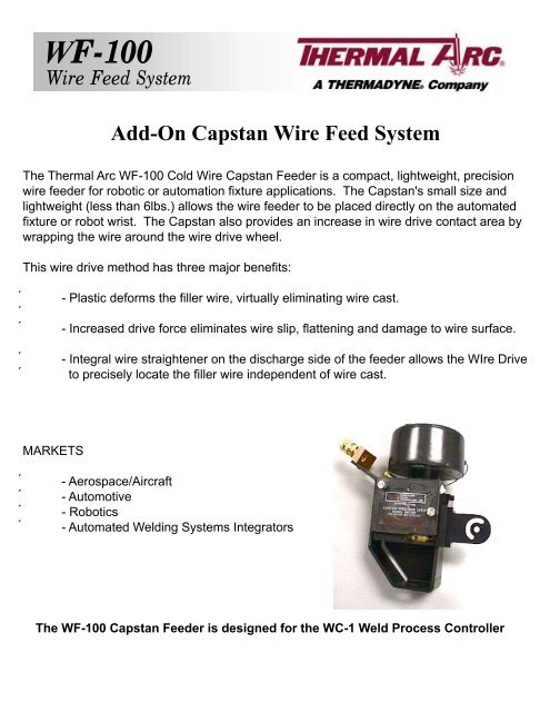
WF-100<strong>Wire</strong> Feed SystemAdd-On <strong>Capstan</strong> <strong>Wire</strong> Feed SystemThe Thermal Arc WF-100 Cold <strong>Wire</strong> <strong>Capstan</strong> <strong>Feeder</strong> is a compact, lightweight, precisionwire feeder for robotic or automation fixture appli<strong>ca</strong>tions. The <strong>Capstan</strong>'s small size <strong>and</strong>lightweight (less than 6lbs.) allows the wire feeder to be placed directly on the automatedfixture or robot wrist. The <strong>Capstan</strong> also provides an increase in wire drive contact area bywrapping the wire around the wire drive wheel.This wire drive method has three major benefits:- Plastic deforms the filler wire, virtually eliminating wire <strong>ca</strong>st.- Increased drive force eliminates wire slip, flattening <strong>and</strong> damage to wire surface.- Integral wire straightener on the discharge side of the feeder allows the WIre Driveto precisely lo<strong>ca</strong>te the filler wire independent of wire <strong>ca</strong>st.MARKETS- Aerospace/Aircraft- Automotive- Robotics- Automated Welding Systems IntegratorsThe WF-100 <strong>Capstan</strong> <strong>Feeder</strong> is designed for the WC-1 Weld Process <strong>Control</strong>ler
Ordering InformationDescriptionPLASMA WELDING SYSTEM CONFIGURATION......................................................................................1WF-100 CAPSTAN WIRE FEEDER ............................................................................................................3SYSTEM DESCRIPTION ......................................................................................................................3DRIVE TYPES .......................................................................................................................................4PRODUCT MANUALS...........................................................................................................................4FILLER WIRE SPECIFICATIONS .........................................................................................................40.030” to 0.052” STEEL ALLOY WIRE CONFIGURATIONS................................................................5CAPSTAN DRIVE TORCH BRACKET ASSEMBLY ...................................................................................7ADJUSTABLE ROBOTIC MOUNT ASSEMBLY .........................................................................................8PIVOT LINK ARM .........................................................................................................................................9LINER/CASING RETAINER .........................................................................................................................9WIRE SPOOL ASSEMBLY.........................................................................................................................10WIRE SPOOL LINER ASSEMBLIES .........................................................................................................11ARTICULATOR LINER AND CASING.......................................................................................................12COLD WIRE PLASMA TORCH ARTICULATOR ASSEMBLY..................................................................13CONTACT TIPS..........................................................................................................................................15Page
<strong>Capstan</strong> <strong>Wire</strong> <strong>Feeder</strong> <strong>and</strong> <strong>Control</strong>Parts ListPLASMA WELDING SYSTEM CONFIGURATIONThese illustrations indi<strong>ca</strong>te the st<strong>and</strong>ard equipment required for a Plasma welding configuration.<strong>Wire</strong> Spool Liner Assembly(See Page 17)<strong>Wire</strong> Spool AssemblyP/N: S2A5001(See Page 10)<strong>Capstan</strong> <strong>Wire</strong><strong>Feeder</strong> Mounting(See Next Page)1-3/8” AdjustableArticulator AssemblyP/N: E2A5194(See Page 13)Contact Tips(See Page 15)Articulator Liner <strong>and</strong> Casing(See Page 12)Plasma Welding <strong>Wire</strong> Feed System ConfigurationEffective 06-01-02Page 1
<strong>Capstan</strong> <strong>Wire</strong> <strong>Feeder</strong> <strong>and</strong> <strong>Control</strong>Parts List<strong>Capstan</strong> <strong>Wire</strong> <strong>Feeder</strong>(See Page 3)Adjustable RoboticMount Assembly(See Page 8)Torch Bracket AssemblyP/N: E2A5190(See Page 7)Liner/Casing RetainerP/N: S2A5002(See Page 9)Pivot Link ArmP/N: E2M5816(See Page 9)<strong>Capstan</strong> <strong>Wire</strong> <strong>Feeder</strong> MountingEffective 06-01-02Page 2
<strong>Capstan</strong> <strong>Wire</strong> <strong>Feeder</strong> <strong>and</strong> <strong>Control</strong>Parts ListWF-100 CAPSTAN WIRE FEEDERSYSTEM DESCRIPTIONThe <strong>Capstan</strong> <strong>Wire</strong> <strong>Feeder</strong> is a compact, lightweightprecision wire feeder for robotic or automated fixtureappli<strong>ca</strong>tions. This product was introduced in 1989.Industry analysts project dramatic growth in the use ofrobots for arc welding in future years. In a r<strong>and</strong>om surveyby an independent consultant 21 out of 55 people interviewedhad robotic or fully auotmated welding operations <strong>and</strong> 12people out of 21 who did have robotoc or auotmated weldingoperations experienced problems with feeding welding wire.Major problems cited were wire <strong>ca</strong>st, helix, <strong>and</strong> wire feedspeed control.The <strong>Capstan</strong>'s small size <strong>and</strong> light weight (less than 6 lbs.)allows the wire feeder to be placed directly on the automated fixture or robot wrist, The <strong>Capstan</strong>also provides an increase in wire drive contact area by wrapping the wire around the wire drive wheel.This wire drive method has three major benefits:Plastic deforms the filler wire, virtually eliminating existing wire <strong>ca</strong>st.Increased drive force eliminates wire slip, flattening <strong>and</strong> damage to wire surface.Integral wire straightener on the discharge side of the feeder allows the <strong>Wire</strong> Drive to preciselylo<strong>ca</strong>te the filler wire independent of wire <strong>ca</strong>st.The WF-100 <strong>Capstan</strong> wire feed drive <strong>ca</strong>n be used with the WC-1 Thermal Arc Process <strong>Control</strong>lerMARKETSAerospace/AircraftAutomotiveAutomotive Satellite IndustriesOEM's - Arc Welding RobotsAutomated Welding Systems IntegratorsADVANTAGES OVER COMPETITION<strong>Wire</strong> feed speed accuracyBroad dynamic rangeBetter/more versatile controlBetter control over wire position in the weld jointAbility to mount on robot armCompetitive priceProcess versatility (GTAW, PAW)Effective 06-01-02Page 3
<strong>Capstan</strong> <strong>Wire</strong> <strong>Feeder</strong> <strong>and</strong> <strong>Control</strong>Parts ListDRIVE TYPESThe WF-100 <strong>Capstan</strong> <strong>Wire</strong> Drive <strong>ca</strong>n be purchased in various configurations as follows:PART NO.E2A5099DESCRIPTIONWF-100 PWM Drive with 9 CM Motor<strong>Wire</strong> Feed Range: 10 - 625 IPM (4-265 mm/s)Motor Full Load Pull Capacity: 20 LBS (9 kg)Operation / Installation ManualNote: WF-100 Drives are not equipped with any specific wire component parts. Specific wire kits must beordered separately for each wire diameter <strong>and</strong> filler wire material.Interface <strong>Control</strong> Circuit for WC-1 Process <strong>Control</strong>lerPART NO.C3A5005DESCRIPTIONInterface <strong>Control</strong> Circuit (Includes <strong>Wire</strong> Feed Printed Circuit Board)Note: Must be ordered when using WC-1 Process <strong>Control</strong>lerFILLER WIRE SPECIFICATIONSThe WF-100 requires different component parts for each diameter of filler wire used. Refer to nextsections to select the correct drive wheel <strong>and</strong> inlet wire guide for the wire diameter <strong>and</strong> filler wire materialrequired. There are four primary configurations for the WF-100.1. 0.030” to 0.052” Steel Alloy <strong>Wire</strong> Configuration2. 0.030” to 0.062” Aluminum <strong>Wire</strong> Pick-up Block Configuration3. 0.030” to 0.052” Aluminum <strong>Wire</strong> Straightener Configuration4. 0.062” Aluminum <strong>Wire</strong> Straightener ConfigurationEffective 06-01-02Page 4
<strong>Capstan</strong> <strong>Wire</strong> <strong>Feeder</strong> <strong>and</strong> <strong>Control</strong>Parts List0.030” to 0.052” STEEL ALLOY WIRE CONFIGURATIONSWhen using a 0.030” to 0.052” steel alloy filler wire with the <strong>ca</strong>pstan, a Steel Alloy <strong>Wire</strong> Kit specifi<strong>ca</strong>llymade for each size wire must be installed on the <strong>ca</strong>pstan. All parts that are wire size specific in these kitsare marked with color codes to prevent mixing incompatible parts. Figure 1 shows all the parts that areincluded in these kits. The <strong>ca</strong>pstan drive is not part of these kits.CONFIGURATION KITSWIRE SIZE COLOR CODES PART NO.0.030” (0.8mm) White E2A51640.035” (0.9mm) Red E2A51650.040” (1.0mm) Gold E2A51660.045” (1.1mm) Yellow E2A51670.047” (1.2mm) Yellow E2A51670.052” (1.3mm) Blue E2A5168COMPONENT PARTSThe drawing below shows the lo<strong>ca</strong>tion of the common <strong>and</strong> wire specific parts that are included in the Steel Alloy<strong>Wire</strong> Kits.<strong>Wire</strong> Feed Cover (not included in kits)6-32 x 1/4 Lg. Socket Head Cap Screw4 Places<strong>Capstan</strong> Wheel (see next page)10-32 x 3/4 Lg. Button Hd Screw6-32 x 3/4 Lg. Button Hd Screw2 PlacesStripper Cover P/N: E2M5592Bearing P/N: X2B0373Stripper Bearing SpacerP/N: E2M5590Stripper P/N: E2M5593Cam Follower P/N: X2B5028#10 Internal Lock Washer8-32 x 3/16 Lg. Sckt. Set ScrewO-Ring P/N: X4S5010<strong>Wire</strong> Out Guide P/N: E2M5594Hex Fitting P/N: X6F5061Torch Liner (see next page)Liner - 1' Long P/N: X7C5033Inlet <strong>Wire</strong> Guide (see next page)Spring P/N: X2N5003St<strong>and</strong>ard H<strong>and</strong> <strong>Capstan</strong> Drive(not included in kits)Figure 1: Steel Alloy <strong>Wire</strong> Component PartsEffective 06-01-02Page 5
<strong>Capstan</strong> <strong>Wire</strong> <strong>Feeder</strong> <strong>and</strong> <strong>Control</strong>0.030” to 0.052” STEEL ALLOY WIRE CONFIGURATIONSPART NO.E2M5583E2M5157E2M5633E2M5156E2M5584E2M5616E2M5617E2M5634E2M5619E2M5620E7C5001E7C5002E2M5590E2M5592E2M5593E2M5594X2B0373X2B5028X2N5003X4S5010X6F5061X7C5033DESCRIPTION<strong>Capstan</strong> Wheel for 0.030" (0.8mm) <strong>Wire</strong><strong>Capstan</strong> Wheel for 0.035" (0.9 mm) <strong>Wire</strong><strong>Capstan</strong> Wheel for 0.040" (1.0 mm) <strong>Wire</strong><strong>Capstan</strong> Wheel for 0.045" (1.1 mm) <strong>and</strong> 0.047" (1.2 mm) <strong>Wire</strong><strong>Capstan</strong> Wheel for 0.052" (1.3 mm) <strong>Wire</strong>Inlet <strong>Wire</strong> Guide for 0.030" (0.8 mm) <strong>Wire</strong>Inlet <strong>Wire</strong> Guide for 0.035" (0.9 mm) <strong>Wire</strong>Inlet <strong>Wire</strong> Guide for 0.040" (1.0 mm) <strong>Wire</strong>Inlet <strong>Wire</strong> Guide for 0.045" (1.1 mm) <strong>and</strong> 0.047" (1.2 mm) <strong>Wire</strong>Inlet <strong>Wire</strong> Guide for 0.052" (1.3 mm) <strong>Wire</strong>Torch Liner for 0.030" (0.8 mm) <strong>Wire</strong> to 0.047" (1.2 mm) <strong>Wire</strong>Torch Liner for 0.052" (1.3 mm) <strong>Wire</strong>Stripper Bearing SpacerStripper CoverStripper<strong>Wire</strong> Out GuideBearingCam FollowerPressure Roller Shoe SpringO-RingHex FittingLiner, 1 foot longEffective 06-01-02Page 6
<strong>Capstan</strong> <strong>Wire</strong> <strong>Feeder</strong> <strong>and</strong> <strong>Control</strong>Parts ListCAPSTAN DRIVE TORCH BRACKET ASSEMBLYBracket Assembly is required to install our Articulator Liner <strong>and</strong> Casing onto the <strong>Capstan</strong> Drive.It includes a quick disconnect fitting for easy installation of welding wire liner.ASSEMBLIESPART NO.E2A5190DESCRIPTION<strong>Capstan</strong> Drive Torch Bracket AssemblyE2M5810X6F5090E2M5813COMPONENT PARTSPART NO.E2M5813E2M5810X6F5090<strong>Capstan</strong> Drive Torch BracketInsulating BlockQuick Disconnect FittingDESCRIPTIONEffective 06-01-02Page 7
<strong>Capstan</strong> <strong>Wire</strong> <strong>Feeder</strong> <strong>and</strong> <strong>Control</strong>Parts ListADJUSTABLE ROBOTIC MOUNT ASSEMBLYRobotic Mount <strong>ca</strong>n be installed onto <strong>Capstan</strong> with or without the Torch Bracket installed. Also, it <strong>ca</strong>n beinstalled on either side of <strong>Capstan</strong>.ASSEMBLIESPART NO.E2M5646E2A5120DESCRIPTIONAdjustable Robotic Mount Assembly for Right Side MountingAdjustable Robotic Mount Assembly for Left Side MountingE2M5710E2M5711Right Side MountingLeft Side MountingCOMPONENT PARTSPART NO.E2M5710E2M5711Bracket BaseBracket ArmDESCRIPTIONNote: Both right <strong>and</strong> left side mountings use the same component parts.Effective 06-01-02Page 8
PIVOT LINK ARM<strong>Capstan</strong> <strong>Wire</strong> <strong>Feeder</strong> <strong>and</strong> <strong>Control</strong>Parts ListPivot Link Arm operates with the Robotic Mount to make pivot adjusts for the <strong>Capstan</strong> <strong>Wire</strong> <strong>Feeder</strong>. TheArm has five mounting holes for installation onto your fixture.ASSEMBLIESPART NO.E2M5816Pivot Link ArmDESCRIPTIONLINER/CASING RETAINERThis retainer is an inexpensive way to <strong>ca</strong>pture welding wire liner <strong>and</strong> <strong>ca</strong>sing.ASSEMBLIESPART NO.S2A5002Casing/Liner RetainerDESCRIPTIONEffective 06-01-02Page 9
WIRE SPOOL ASSEMBLY<strong>Capstan</strong> <strong>Wire</strong> <strong>Feeder</strong> <strong>and</strong> <strong>Control</strong>Parts ListThis assembly will accommodate a 12” diameter welding wire spool. It issupplied with a quick disconnect fitting for easy installation of welding wireliner <strong>and</strong> <strong>ca</strong>sing.ASSEMBLIESPART NO.S2A5001<strong>Wire</strong> Spool AssemblyDESCRIPTIONCOMPONENT PARTSPART NO.S2M5027S2M5028S2M5029S2M5177X6Z5053X6F5090X6F5105DESCRIPTION<strong>Wire</strong> Spool St<strong>and</strong><strong>Wire</strong> Spool Arm<strong>Wire</strong> Spool Cover<strong>Wire</strong> Spool Shaft BracketSpool Holder AssemblyFemale Quick Disconnect Fitting¼” NPT Female x ½” NPT Male PVC Schedule 80 BushingEffective 06-01-02Page 10
<strong>Capstan</strong> <strong>Wire</strong> <strong>Feeder</strong> <strong>and</strong> <strong>Control</strong>Parts ListWIRE SPOOL LINER ASSEMBLIESOur <strong>Wire</strong> Spool Liner Assemblies are supplied in 10’ <strong>and</strong> 15’ lengths for both steel alloy <strong>and</strong> aluminumwire. They are supplied with quick disconnect fittings for ease of installation to <strong>Wire</strong> Spool Assembly <strong>and</strong><strong>Capstan</strong> <strong>Wire</strong> <strong>Feeder</strong>.ASSEMBLIESPART NO.E7A5001E7A5002E7A5003E7A5004E7A5005E7A5006E7A5007E7A5008E7A5009E7A5010DESCRIPTION10’ Long Assembly for 0.030” – 0.047” Steel Alloy <strong>Wire</strong>15’ Long Assembly for 0.030” – 0.047” Steel Alloy <strong>Wire</strong>10’ Long Assembly for 0.052” – 0.062” Steel Alloy <strong>Wire</strong>15’ Long Assembly for 0.052” – 0.062” Steel Alloy <strong>Wire</strong>10’ Long Assembly for 0.030” – 0.035” Aluminum <strong>Wire</strong>15’ Long Assembly for 0.030” – 0.035” Aluminum <strong>Wire</strong>10’ Long Assembly for 0.040” – 0.052” Aluminum <strong>Wire</strong>15’ Long Assembly for 0.040” – 0.052” Aluminum <strong>Wire</strong>10’ Long Assembly for 0.062” Aluminum <strong>Wire</strong>15’ Long Assembly for 0.062” Aluminum <strong>Wire</strong>10’ or 15’QD FittingP/N: X6F5102Tube FittingP/N: X6F5104LinerCasingTube FittingP/N: X6F5104Modified QD FittingP/N: E2M5824LinerCOMPONENT PARTSPART NO.E7C5007E7C5008E7C5009E7C5010E7C5011E7C5012E7C5013E7C5014E7C5015E7C5016E7C5017E7C5018X6F5104E2M5824X6F5102DESCRIPTION10’ Long Liner for 0.030” – 0.047” Steel Alloy <strong>Wire</strong>15’ Long Liner for 0.030” – 0.047” Steel Alloy <strong>Wire</strong>10’ Long Liner for 0.052” Steel Alloy <strong>Wire</strong>15’ Long Liner for 0.052” Steel Alloy <strong>Wire</strong>10’ Long Liner for 0.030” – 0.035” Aluminum <strong>Wire</strong>15’ Long Liner for 0.030” – 0.035” Aluminum <strong>Wire</strong>10’ Long Liner for 0.040” – 0.052” Aluminum <strong>Wire</strong>15’ Long Liner for 0.040” – 0.052” Aluminum <strong>Wire</strong>10’ Long Liner for 0.062” Aluminum <strong>Wire</strong>15’ Long Liner for 0.062” Aluminum <strong>Wire</strong>10’ Long Liner Casing15’ Long Liner CasingTube FittingModified Quick Disconnect FittingMale Quick Disconnect FittingEffective 06-01-02Page 11
<strong>Capstan</strong> <strong>Wire</strong> <strong>Feeder</strong> <strong>and</strong> <strong>Control</strong>Parts ListARTICULATOR LINER AND CASINGThese Articulator Liners <strong>and</strong> Casings are 3 foot long but <strong>ca</strong>n be supplied in longer lengths as required forboth steel alloy <strong>and</strong> aluminum wire.ASSEMBLIESPART NO.E7A5011E7A5012E7A5013E7A5014E7A5015DESCRIPTION3’ Long Assembly for 0.030” – 0.047” Steel Alloy <strong>Wire</strong>3’ Long Assembly for 0.052” – 0.062” Steel Alloy <strong>Wire</strong>3’ Long Assembly for 0.030” – 0.035” Aluminum <strong>Wire</strong>3’ Long Assembly for 0.040” – 0.052” Aluminum <strong>Wire</strong>3’ Long Assembly for 0.062” Aluminum <strong>Wire</strong>3’LinerLiner CasingCOMPONENT PARTSPART NO.E7C5019E7C5020E7C5021E7C5022E7C5023E7C5024DESCRIPTIONLiner for 0.030” – 0.047” Steel Alloy <strong>Wire</strong>Liner for 0.052” Steel Alloy <strong>Wire</strong>Liner for 0.030” – 0.035” Aluminum <strong>Wire</strong>Liner for 0.040” – 0.052” Aluminum <strong>Wire</strong>Liner for 0.062” Aluminum <strong>Wire</strong>Liner CasingEffective 06-01-02Page 12
<strong>Capstan</strong> <strong>Wire</strong> <strong>Feeder</strong> <strong>and</strong> <strong>Control</strong>Parts ListCOLD WIRE PLASMA TORCH ARTICULATOR ASSEMBLYThe Articulator Assembly provides a convenient means for adjusting the position of the cold wire withrespect to the PAW welding torch. The articulator provides X –Y– Z-axis motion <strong>and</strong> a pivot axis for wireimpingement angle. The cold wire feed guide assembly is isolated from the torch mount <strong>and</strong> uses areplaceable contact tip. The articulator may be used as a hot wire torch by connecting a power <strong>ca</strong>ble tothe wire guide assembly.COMPLETE ASSEMBLIESPART NO.E2A5194DESCRIPTION1-3/8” Adjustable Articulator AssemblyNote: Contact tips are not supplied with assemblies. See Component Parts below for a list of contact tips.Effective 06-01-02Page 13
<strong>Capstan</strong> <strong>Wire</strong> <strong>Feeder</strong> <strong>and</strong> <strong>Control</strong>Parts List116Plasma Torch(Reference Only)14 57931484 13151021512Contact Tip (For Reference Only)COMPONENT PARTSITEM PART NO. DESCRIPTION1 E2M5762 Articulator “Y” Adjust Clamp2 E2M5763 Articulator Tip Retainer3 E2M5838 1-3/8” Articulator Front Torch Barrel Clamp4 E2M5839 1-3/8” Articulator Rear Torch Barrel Clamp5 E2M5840 Articulator “XY” Adjust Clamp6 E2M5841 Articulator “X” Adjust Shaft7 E2M5842 Articulator “Y” Adjust Shaft8 E2M5843 Hex Adaptor9 X6F5085 5/16” Tube Fitting10 #8-32 x 1-1/2” Long Socket Cap Head Screw11 #8-32 x 1/2” Long Socket Cap Head Screw12 #8-32 x 7/8” Long Socket Cap Head Screw13 #8-32 Hex Nut14 #10-32 x 1/4” Long Socket Set Screw15 #5/16-18 Hex NutEffective 06-01-02Page 14
<strong>Capstan</strong> <strong>Wire</strong> <strong>Feeder</strong> <strong>and</strong> <strong>Control</strong>Parts ListCONTACT TIPSListed below are the contact tips for the Articulator Assembly.COMPONENT PARTSPART NO.X7T5005X7T5003X7T5004X7T5033X7T5034X7T5026X7T5002X7T5035X7T5027DESCRIPTION0.030" Solid or Flux Core <strong>Wire</strong>0.035" Solid or Flux Core <strong>Wire</strong>0.045"/0.047” Solid or Flux Core <strong>Wire</strong>0.052” Solid or Flux Core <strong>Wire</strong>0.030" Aluminum or Stainless Steel <strong>Wire</strong>0.035" Aluminum or Stainless Steel <strong>Wire</strong>0.045"/0.047” Aluminum or Stainless Steel <strong>Wire</strong>0.052” Aluminum or Stainless Steel <strong>Wire</strong>0.062" Aluminum or Stainless Steel <strong>Wire</strong>NOTE: Consult factory for additional required components <strong>and</strong> pricing.Form No. 84-2230 (8/02)