Fascia Mount Testing Report - Morse Industries
Fascia Mount Testing Report - Morse Industries
Fascia Mount Testing Report - Morse Industries

You also want an ePaper? Increase the reach of your titles
YUMPU automatically turns print PDFs into web optimized ePapers that Google loves.
Materials TechnologyMr. Pat HutchinsonR & B Wagner, Inc.10600 West Brown Deer RoadMilwaukee, WI 53224Stork Technimet, Inc.Failure Analysis • Materials <strong>Testing</strong> • Product Evaluation3200 S. 166th StreetNew Berlin, Wisconsin 53151-4141 USATelephone : (262) 782-6344Toll Free : (800) 726-6385Telefax : (262) 782-3653E-Mail : stork.technimet@stork.comWebsite : www.storksmt.com/technimet<strong>Report</strong> No. 0808-24792-2EVALUATION OFFASCIA MOUNT BASE SHOERob M. EvansNovember 14, 2008It is our policy to retain components and sample remnants for a minimum of 30 days from the report date, after which time they may bediscarded. The data herein represents only the item(s) tested. This report shall not be reproduced, except in full, without priorpermission of Stork Technimet, Inc.Stork Technimet, Inc. is an operating unit of Stork Materials Technology B.V.,Amsterdam, The Netherlands, which is a member of the Stork group.Page 1 of 10
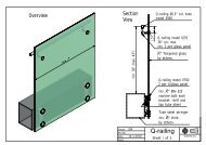
Materials TechnologyStork Technimet, Inc.DESCRIPTION AND PURPOSER & B Wagner, Inc. requested Stork Technimet to evaluate a base shoe used in commercialrailings. This base shoe was a 4 inch tall, 2.5 inch wide aluminum channel. The base shoewas five feet long, and had five countersunk holes through one side, spaced 12 inches apart.This base shoe was designed to be used with a half-inch thick, tempered glass panel as aninfill. The infill can be secured to the base shoe using plastic isolators and Panel Grips, orcan be grouted in place. In this case, it was requested to evaluate the base shoe whenmounted to a wall, or “fascia mounted,” and using panel grips.The test of this base shoe was to be according to the procedure listed in ASTM E 935,“Standard Test Methods for Performance of Permanent Metal Railing Systems and Railsfor Buildings.” The horizontal deflection was measured at the top of the rail, and evaluatedagainst the criteria in ASTM E 985, “Standard Specifications for Permanent Railing Systemsand Rails for Buildings.” Stork Technimet previously evaluated similar systems with theresults of the most recent testing presented in Stork Technimet <strong>Report</strong> No. 0804-23452,dated May 2, 2008.CONCLUSIONSThree base shoes were tested with a steel railing and one with a glass panel. Four sampleswere tested according to ASTM E 935 with a load applied at either the top-center or the cornerof the rail. At the test load of 365 pounds, the steel rail deflected 1.895, 1.978, and 1.761inches. The allowable deflections were 2.42, 2.42 and 3.58 inches, respectively. The glasspanel deflected 2.035 inches at 365 pounds with an allowable deflection of 2.38 inches. Thesewere less than the maximum allowable.The residual deflections of the steel rail after releasing the 365 pound test load were 0.198,0.291, and 0.207 inches. The allowable residual deflections were 0.483, 0.483, and 0.5inches, respectively. The residual deflection of the glass panel after releasing the 365 poundtest load was 0.099 inches with an allowable of 0.475 inches. These were less than themaximum allowable.PROCEDURE AND RESULTSFour aluminum base shoes were tested in accordance with ASTM E 935 except that a steelrailing was substituted for the typical glass panel for three of the tests. R & B Wagner, Inc.provided the steel railing, glass panel, aluminum base shoes, and the Panel Grips andperformed the installations. The base shoes were bolted to a steel plate, which was anchoredto a concrete slab. A welded steel railing or glass panel was installed in each base shoe usingfour Panel Grips set at approximately 12 inches on center.For each test, load was applied to the steel railing using a winch, and the load was measuredwith a load cell. The displacement was measured as near as practical to the load applicationpoint with a “String Pot” or Linear Displacement Transducer (LDT). The load was applied and<strong>Report</strong> No. 0808-24792-2 (REVISED) November 14, 2008 Page 2 of 10
Materials TechnologyStork Technimet, Inc.the deflection was measured at a height of approximately 43 inches for the steel railing,and 42 inches for the glass panel. This approximates the top of a typical railing.Photographs of the test setups are provided as Figures 1 through 3.At the start of each test, a preload of 180 pounds was applied and held for twominutes. The preload was then released to half, or 90 pounds. This was consideredto be the zero point per ASTM E 935. The load was then applied in increments ofapproximately 100 pounds using the winch until the desired load was achieved. Eachload was held for approximately 2 minutes. The samples were loaded to a maximum of365 pounds according to ASTM E 935, and then the load was reduced to 90 pounds todetermine the residual displacement. In addition to the requirements of ASTM E 935,the samples were also overloaded to 550 pounds. Three samples were loaded with theload centered at the midspan, and one sample was loaded with a load near the corner,as outlined in ASTM E 935.Load and displacement data were recorded continuously with an eDAQ portable dataacquisition system. The load-displacement plots for each sample are included as Figures 4through 7. The displacements at 365 pounds varied from 1.761 inches to 2.035 inches, andthe residual deflections ranged from 0.099 inches to 0.291 inches. These values of deflectionand residual deflection were within the allowable range. The results of the tests and thedeflection criteria defined in ASTM E 985 are listed in Table 1.If you have any questions concerning the contents of this report, please contact me. Itshould be noted that it is our policy to retain components and sample remnants for 30 daysfrom August 29, 2008, after which time they will be discarded. If you would like to makealternate arrangements for disposition of the material, please let me know. This project shallbe governed exclusively by the General Terms and Conditions of Sale and Performance of<strong>Testing</strong> Services by Stork Technimet, Inc. a Wisconsin business corporation d.d. March 22,2004. In no event shall Stork Technimet, Inc. be liable for any consequential, special orindirect loss or any damages above the cost of the work.Respectfully submitted,Rob M. EvansMechanical EngineerPhilip M. Dindinger, P.E.Senior Engineer<strong>Report</strong> No. 0808-24792-2 (REVISED) November 14, 2008 Page 3 of 10
Materials TechnologyStork Technimet, Inc.TestInfillLoadPointTable 1Load-Deflection Test ResultsAt365lbs.Allowableat 365 lbs.Deflections (inches)Residual*AllowableResidualAt550lbs.1 Steel Middle 1.895 2.42 0.198 0.483 3.3142 Steel Middle 1.978 2.42 0.291 0.483 3.4553 Steel Corner 1.761 3.58 0.207 0.5 3.2094 Glass Middle 2.035 2.38 0.099 0.475 3.838* Residual measured after loading to 365 pounds and releasing to 90 pounds.<strong>Report</strong> No. 0808-24792-2 (REVISED) November 14, 2008 Page 4 of 10
Materials TechnologyStork Technimet, Inc.Fig. 1 -An overall view of the first test setup is shown. The load was applied at the center ofthe of the substitute steel rail.Fig. 2 -An overall view of the second test setup is shown. The load was applied near thecorner of the of the substitute steel rail.<strong>Report</strong> No. 0808-24792-2 (REVISED) November 14, 2008 Page 5 of 10
Materials TechnologyStork Technimet, Inc.Fig. 3 -An overall view of the glass panel test setup is shown. The load was applied at thecenter of the top edge of the glass panel. Wood blocks were used to distribute theclamping pressure and prevent fracture of the glass.<strong>Report</strong> No. 0808-24792-2 (REVISED) November 14, 2008 Page 6 of 10
Materials TechnologyStork Technimet, Inc.600Sample 1 - Load Deflection With Steel RailCenter Load500400Load (pounds)300200100Residual Deflectionafter 365 pound load00 0.5 1 1.5 2 2.5 3 3.5Displacement (inches)Fig. 4 -A plot of load versus deflection for steel rail sample one with center loading.<strong>Report</strong> No. 0808-24792-2 (REVISED) November 14, 2008 Page 7 of 10
Materials TechnologyStork Technimet, Inc.600Sample 2 - Load Deflection With Steel RailCenter Load500400Load (pounds)300200100Residual Deflectionafter 365 pound load00 0.5 1 1.5 2 2.5 3 3.5 4Displacement (inches)Fig. 5 -A plot of load versus deflection for steel rail sample two with center loading.<strong>Report</strong> No. 0808-24792-2 (REVISED) November 14, 2008 Page 8 of 10
Materials TechnologyStork Technimet, Inc.600Sample 3 - Load Deflection With Steel RailCorner Load500400Load (pounds)300200100Residual Deflectionafter 365 pound load00 0.5 1 1.5 2 2.5 3 3.5Displacement (inches)Fig. 6 -A plot of load versus deflection for steel rail sample three with corner loading.<strong>Report</strong> No. 0808-24792-2 (REVISED) November 14, 2008 Page 9 of 10
Materials TechnologyStork Technimet, Inc.600Sample 4 - Load Deflection With Glass PanelCenter Load500400Load (pounds)300200100Residual Deflectionafter 365 pound load00 0.5 1 1.5 2 2.5 3 3.5 4 4.5Displacement (inches)Fig. 7 -A plot of load versus deflection for glass panel sample four with center loading.<strong>Report</strong> No. 0808-24792-2 (REVISED) November 14, 2008 Page 10 of 10