MSD 8971 Dual Mag Timing Controller - MSD Pro-Mag.com
MSD 8971 Dual Mag Timing Controller - MSD Pro-Mag.com
MSD 8971 Dual Mag Timing Controller - MSD Pro-Mag.com
- No tags were found...

Create successful ePaper yourself
Turn your PDF publications into a flip-book with our unique Google optimized e-Paper software.
<strong>MSD</strong> <strong>8971</strong> <strong>Dual</strong> <strong>Mag</strong> <strong>Timing</strong> <strong>Controller</strong>Operation, <strong>Pro</strong>gramming and Diagnostics6 January 2004The <strong>8971</strong> timing controller is programmed only with the <strong>MSD</strong> 7570 Graphics editor,which is a handheld device with an LCD touch screen. All the timing data is entered bytouching the LCD screen to select an edit function and then moving the selected datapoint by dragging it on the screen or by touching the UP, Down, Left or Right screenbuttons. See the figures illustrating the various LCD edit screens for the user selectablefunctions.The <strong>8971</strong> timing controller allows the user to program a timing retard curve with from 1to 30 data points. These data points can be moved in a range from 0 to 6 seconds, in .05second increments and with an ignition timing retard value of 0 to 30 degrees in .5 degreeincrements. Also the user can program a Pedal Lift feature, which allows three values tobe programmed, Pedal degrees, Pedal Ramp, and Pedal Inhibit. The Pedal degree value isselected to cause the ignition timing to retard to the Pedal Degree value when the throttleis lifted which deactivates the dark blue wire connected to the wide-open-throttle switch.The Pedal degree value is programmable from 0 to 30 degrees in .5-degree increments.The Pedal Ramp is programmed to ramp the ignition timing from the Pedal degree valueto the elapsed timing curve so that the ignition retard is smoothly ramped back to thecurve retard value. The Pedal Ramp value is programmable from 0 to 2.50-seconds in.01-second increments. The Pedal Inhibit value is programmable to disable or inhibit thePedal Lift Retard until the Pedal Inhibit time has elapsed from the launch, when the WOTswitch was activated to begin the retard curve timer. The Pedal Inhibit function allowsthe <strong>8971</strong> to ignore pedal lifts during the programmed time from launch so that the retardcurve will be in full authority during the programmed Pedal Inhibit time and then allowthe Pedal Degree value to override the timing curve when the driver lifts the throttle.This feature allows the driver to pedal the car off the line with no pedal lift retard untilthe desired programmed time after the launch.Note: The wide-open throttle switch must be a switch activated by sensing the pedalmovements preferably mounted near the top of the throttle pedal. This switch must bedeactivated quickly when the throttle is lifted and reactivate quickly when the throttle isreturned to full throttle. An air activated switch must not be used to properly activate thedark blue launch wire! Use only a high quality microswitch such as the type found on the<strong>Pro</strong>Stock cars clutch switch.The Reset wire input is a momentary switch that should be activated before the launch,which then will select the first retard timing data point in the retard curve. When the <strong>8971</strong>is properly reset the two red LED’s on the <strong>8971</strong> end panel will illuminate and stayilluminated until the Launch wire is activated at which time the two red LED’s turn offand the two green LED’s illuminate while the WOT switch is activated to start the timingretard timer. The two green LED’s will blink rapidly when the WOT switch isdeactivated during a pedal lift even though the retard timer still runs. If the reset switch isactivated any time after a valid launch sequence the retard timer is reset and ignition1
<strong>8971</strong> Monitor Messages:<strong>Mag</strong>Deg-0.0------+9.9 to –9.9 Deg, .1Deg incrementsMis<strong>Mag</strong>A 000----0 to 255 only displayed if >0Mis<strong>Mag</strong>B 000----0 to 255 only displayed if >0Dist----------------indicates the type of mag-pickup input as a distributor reluctorCrank-------------indicates the type of mag-pickup input as a crank triggerThe lower right message line on the 7570 LCD screen displays warning and alertmessages from the <strong>8971</strong> timing controller while it is operating or the PC.<strong>8971</strong> Warning Messages:TCDA 00.0 Hrs----0-24 Hours, in .1 hour increments displayed if >0TCDB 00.0 Hrs----0-24 Hours, in .1 hour increments displayed if >0RstA 00.0 Hrs------0-24 Hours, in .1 hour increments displayed if >0RstB 00.0 Hrs------0-24 Hours, in .1 hour increments displayed if >0<strong>Mag</strong>Deg-7.2-------<strong>Mag</strong>input Offset >=5DegLost <strong>Mag</strong>A---------Lost <strong>Mag</strong>A inputLost <strong>Mag</strong>B---------Lost <strong>Mag</strong>B input<strong>8971</strong> Alert Messages:Low Battery-------indicates the 7570 internal battery needs recharging, less than 20minutes of operating time remainVerify Error-------indicates that a file move operation was not successful or data ismismatched from the 7570 screen dataNo Reply A-------indicates that the channel A microcontroller of the <strong>8971</strong> is not<strong>com</strong>municating properly with the 7570No Reply B-------indicates that the channel B microcontroller of the <strong>8971</strong> is not<strong>com</strong>municating properly with the 7570No Reply PC-----indicates that the PC is not <strong>com</strong>municating properly with the 7570Loop Back--------7570 Com port testFile Compare----indicates that there is a mismatch of data on the 7570 screen and the PCor <strong>8971</strong> when the data is transferred or verified<strong>Pro</strong>grammingUsing the 7570 Graphic Editor the <strong>8971</strong> and other future products can be programmedwithout the need of a PC or Laptop <strong>com</strong>puter. The 7570 can be connected to a PC to savethe 6 files to the <strong>com</strong>puter for archiving or printing out a hardcopy of the files saved inthe 7570 EEPROM memory. Using the <strong>MSD</strong> GraphSave software the 7570 can move asingle file at a time to or from the 7570 LCD screen to or from the PC screen. TheGraphSave software allows the user to save the timing curve and data files and notes onthe PC or retrieve the previously saved files from the PC to loaded in the 7570, which canthen be loaded in the <strong>8971</strong> timing controller. Future versions of the <strong>MSD</strong> GraphSavesoftware will allow the timing curves and data to be edited on the PC.3
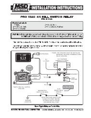
7570 Edit Pedal Screen<strong>MSD</strong> 1.350Sec 21.5Deg Retard <strong>8971</strong>Pedal Lift 25.5 Deg Ramp .37Sec Inh 1.50SecFile 0 1 2 3 4 5 60Pedal Edit button Pressedto allow user to edit thePedal degree valuePedal ramp time orPedal inhibit timeNext press the desiredScreen button for thefunction desiredSendPlotCheckEditPedalEditPointShiftCurveBackLite510152025PedalDegreesPedalRamp30Pedal DegreePedalInhibitUP DOWN ENTERPedal RampUP DOWN ENTER7570screen7a.skfPedal InhibitUP DOWN ENTERAfter the timing retard curve and Pedal Lift values have been edited the screen shouldnext be saved to a file in the 7570, which can be saved into one of 6 files for laterretrieval to load into the <strong>8971</strong> or PC. Press the File button to display the File screen andthen select a file to save the present screen to. Begin with Save1 for the first file. Afterthe Save1 button is pressed the present screen is now saved in the 7570 EEPROM andwill remain there even if power is now turned off. To recall a previously saved file frommemory in the 7570, press File and then # To Screen button to bring the selected filefrom memory to the LCD screen. See the screen illustration below of the File screen.8
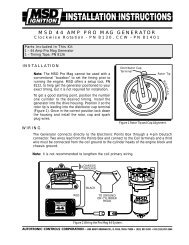
excessively long cable, poor connections on both or either cable end, low battery in 7570or power to the <strong>8971</strong> was corrupted. Check for any of these conditions and resend plotdatauntil Verify OK is displayed. See the illustrated Send Plot screen below.7570 Send Plot Screen<strong>MSD</strong> 1.350Sec 21.5Deg Retard <strong>8971</strong>Pedal Lift 25.5 Deg Ramp .37Sec Inh 1.50SecFile 0 1 2 3 4 5 60Send Plot button Pressedto allow user to send thescreen plot to the <strong>MSD</strong>product connected or tothe PC if connected orto move the file from thePC to the 7570 Screenor from the <strong>MSD</strong> productto the 7570 ScreenNext press the desiredScreen button for the functiondesired.SendPlotCheckEditPedalEditPointShiftCurveBackLite510152025To <strong>MSD</strong>To PC<strong>MSD</strong> ToScreenPC ToScreen30Verify OK-----------------------or-----------------No Reply A,B or PCMessage for move OKMessage for move not <strong>com</strong>pletedMessages will be removed after displaying for 5 secondsOther checks can be performed to verify that the data on the screen is the same data in the<strong>8971</strong> timing controller by pressing the Check button. The Check function is used toverify the last move operation or <strong>com</strong>pare the present LCD screen data with the file dataof the <strong>8971</strong> or PC screen. When the Check button is pressed the Check screen isdisplayed to allow the user to select Verify Move or Reset <strong>Mag</strong>Cnt. When the VerifyMove button is pressed the 7570 will verify that the last move operation, which could bea file save, file move to screen, or transfer to the <strong>8971</strong> or PC was successful and the datamatches the data on the LCD screen. An Alert message is displayed if the data ismismatched or there was no reply from the selected device to <strong>com</strong>municate with. See theillustrated Check Screen below.10
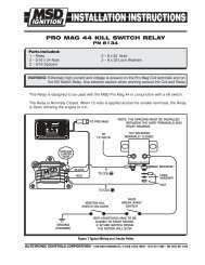
7570 Check Screen<strong>MSD</strong> 1.350Sec 21.5Deg Retard <strong>8971</strong>Pedal Lift 25.5 Deg Ramp .37Sec Inh 1.50SecFile 0 1 2 3 4 5 60Check button Pressedto allow user to verify thelast file move or to resetthe <strong>Mag</strong>countersNext press the desiredscreen button for thefunction desiredSendPlotCheckEditPedalEditPointShiftCurveBackLite510152025VerifyMoveReset<strong>Mag</strong>Cnt30Verify OK -------------------or-------------------No Reply A,B, or PCMessage for move OKMessage for move not <strong>com</strong>pletedMessages will be removed after displaying for 5 secondsThe 7570 can be connected to a PC or Laptop for saving files transferred from the 7570or allowing files to be transferred from the PC to the 7570 using the <strong>MSD</strong> GraphSavesoftware operating on any Windows operating system under Windows 95,98,XP, NT,2000, or Me. All transfers are under the control of the 7570, in that the 7570 will initiateall file transfers to and from the PC screen to the 7570 screen, and then the 7570 screendata maybe saved to a file or <strong>MSD</strong> product such as the <strong>8971</strong>. Only one device either thePC or the <strong>8971</strong> product can be connected to the 7570 at a time. Because only one sharedCom port is available for <strong>com</strong>munications, only one device may be connected at anytime. The PC allows for printing the timing curve data along with the Pedal data valuesand any notes. The file must be opened on the PC before a transfer from the PC to the7570 by pressing the Send To PC button; otherwise a zero data file will be transferred.See the Help file for the <strong>8971</strong>V1 in the <strong>MSD</strong> GraphSave program for more informationon use of the PC with the <strong>8971</strong> and 7570 Graphic Editor.DiagnosticsThe 7570 can be used to help diagnose several problems found in the <strong>8971</strong>, which mayinclude bad or intermittent mag-pickups, improperly phased mag-pickups, missing magpickupsignals, traction control detection, or <strong>com</strong>munication errors to the <strong>8971</strong> or PC.The Mis<strong>Mag</strong> counter will detect when the mag-input signal is missing and count theevent as one event each time the mag-input signal is lost for each mag-input. TheMis<strong>Mag</strong> counter is saved in the <strong>8971</strong> EEPROM so that after a run down the track or evenwith the engine running in the pits if either mag-pickup fails to produce a continuousinput signal the lost mag signal is counted and updates the <strong>8971</strong> memory to be monitored11
y the 7570 while the engine is running or after the run. The Mis<strong>Mag</strong> counter helps todiagnose a failing pickup that might otherwise only happen going down the track and notbe failing in the pits. Pressing the Check button and then the Reset <strong>Mag</strong> Cnt button toreset both Mis<strong>Mag</strong> counters will reset the Mis<strong>Mag</strong> counter; this is done with power on tothe <strong>8971</strong> and the Com cable connected. Since the <strong>8971</strong> has two mag-input channels eachmicrocontroller in the <strong>8971</strong> is constantly <strong>com</strong>paring the quality of both mag-input signalsto determine if one has gone bad by dropping out or bad by providing a noisy signalcaused by a loose connector or open pickup as well as a shorted pickup and rejects thebad pickup within one ignition cycle without letting the bad signal cause miss-triggeringof the magneto. The bad pickup is constantly being monitored to re-qualify for anacceptable input signal if it remains in the proper phase relation ship to the remaininggood pickup for a minimum number of ignition cycles. Even when a bad pickup signal isfound, both magneto trigger outputs use the remaining good pickup signal. Bothmagnetos will always trigger simultaneously from the most retarded pickup of the twoinput signals, even when the pickups are slightly staggered and one pickup is lost the<strong>8971</strong> will maintain the same ignition timing that was provided before the lost pickup.The TCD functions to detect a modified mag-input signal, which may occur when atraction control device is connected to the <strong>8971</strong> timing controller. The action of thetraction control device is very uniquely sensed by the hardware and firmware in the twomicrocontrollers of the <strong>8971</strong>. A shorted or open mag-input will not cause a TCD event tobe set in the <strong>8971</strong> because of the algorithms used to sense the difference between a badpickup and a traction control device modifying the mag-input signal. The <strong>8971</strong> will setthe TCD counter to 24.0 Hrs in memory when a valid TCD event is detected and requiresthat the <strong>8971</strong> by powered on for 24 hours to count down to reset the TCD event and turnoff the flashing red LED on the end panel, which flashes a 2 blink pause repeating TCDcode. The only other means of resetting the TCD code is by the NHRA tech-inspectorskey, which is connected to the <strong>8971</strong> to inspect and/or reset the TCD event code that alsosets the Rst 24.0Hrs counter to indicate the time elapsed from a KEY reset.The Remote mounted LED’s indicate to the crew chief or driver that both channels areproperly reset when the reset is activated and the launch timer is running when the WOTswitch is activated at the launch. The Red LED’s will not illuminate if any alert code isflashing on either channel or if only one channel resets, indicating an alert conditionexists, or one channel microcontroller is not operating. The reset function is activatedwhen the reset switch is activated in the case of alerts blinking. The LED end panelshould be visible to the crew chief when properly mounted in the car so that correctoperation can be verified after the engine is started and when the reset is activated prior tolaunch.The green LED’s can be used to verify proper actuation of the WOT switch byilluminating after a reset when the WOT switch is closed supplying +12 volts to the darkblue wire of the <strong>8971</strong>. When the throttle is lifted the green LED’s should begin rapidlyblinking to indicate the WOT switch is opened.12