Pro Mag Digital Retard Controller-Digital Controller Graphic Editor
Pro Mag Digital Retard Controller-Digital Controller Graphic Editor
Pro Mag Digital Retard Controller-Digital Controller Graphic Editor
- No tags were found...

Create successful ePaper yourself
Turn your PDF publications into a flip-book with our unique Google optimized e-Paper software.
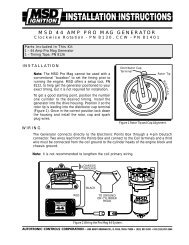
<strong>Pro</strong> <strong>Mag</strong> <strong>Digital</strong> <strong>Retard</strong> <strong>Controller</strong>, PN 8971<strong>Digital</strong> <strong>Controller</strong> <strong>Graphic</strong> <strong>Editor</strong>, PN 7570The <strong>Pro</strong> <strong>Mag</strong> <strong>Digital</strong> <strong>Retard</strong> <strong>Controller</strong> is a programmable timing control designed for the MSD<strong>Pro</strong> <strong>Mag</strong>. It can be used with single and dual <strong>Pro</strong> <strong>Mag</strong> 12 or 44 Amp systems. It is designed to beused with <strong>Pro</strong> <strong>Mag</strong> systems using a crank trigger system using non-magnetic pickups. (Thissystem will operate with the generator’s internal pickup, but is not recommended for accuratetiming.) The <strong>Digital</strong> <strong>Retard</strong> <strong>Controller</strong> has two outputs that share one common timing program.<strong>Pro</strong>gramming the <strong>Controller</strong> can only be achieved through the <strong>Graphic</strong> <strong>Editor</strong>, PN 7570. Thissystem allows you to alter the timing with up to 30 points in 0.5° increments down to every 0.05-seconds for up to 6-seconds. This battery powered <strong>Pro</strong>grammer features an LCD screen thatallows you to plot a timing curve by touching the screen. This <strong>Graphic</strong> <strong>Editor</strong> can be connectedto a PC so you can save your timing curves, or download a curve that you previously downloadedto your PC. Each time the <strong>Editor</strong> is connected to the <strong>Retard</strong> Control, it goes through aseries of checks and verifications for errors and to confirm that both trigger channels are okay.Detailed instructions on the operation of the <strong>Graphic</strong> <strong>Editor</strong> and the installation of the <strong>Retard</strong><strong>Controller</strong> follow. It is important to read and understand the operation of these controls prior tobeginning the installation.Parts Included with <strong>Retard</strong> <strong>Controller</strong>, PN 8971:4 - Vibration Mounts and Hardware6 - Gold Amp Terminals for <strong>Mag</strong> Pickup Trigger Cables2 - <strong>Mag</strong> Pickup/Deutsch Connector HarnessParts Included with <strong>Graphic</strong> <strong>Editor</strong>, PN 7570:1 - RS232 Harness 1 - Software CD, PN 96081 - 120 VAC/9VDC Charging AdapterNote: A heavy duty microswitch is required as a wide open throttle switch. The microswitchshould be mounted near the top of the pedal so it can react quickly. An air activatedswitch is not recommended unless it is a very fast responding design.Important: When the <strong>Digital</strong> <strong>Retard</strong> <strong>Controller</strong> is installed the timing will be 5° retarded.This is due to its improved mag pickup compensation circuit. The timingmust be checked and reset to your engine's specifications.OPERATIONThe PN 8971 <strong>Retard</strong> <strong>Controller</strong> can only be programmed with the MSD PN 7570 <strong>Graphic</strong>s<strong>Editor</strong>. All programming is accomplished through this unit’s LCD touch screen. When the <strong>Editor</strong>is turned On, all the timing data is entered by touching the LCD screen.PROGRAMMINGThe selections on the left side of the screen are the controls for creating, editing and savingyour timing curves. There are also two control buttons, Left and Right, for movement on thebottom right of the screen. (Figure 1)MSD IGNITION • 1490 HENRY BRENNAN DR., EL PASO, TEXAS 79936 • (915) 857-5200 • FAX (915) 857-3344
2 INSTALLATION INSTRUCTIONSFigure 1 <strong>Pro</strong>gram Controls.File: Select out of 12 files which can be opened or saved.Send Plot: This controls where to move a timing chart. You can either: send the plot to the PN 8971,send it to your PC, bring the plot from the PN 8971 to the graphic editor’s LCD screen, or bring it tothe LCD from your PC or move a selection of files from the PC to the <strong>Graphic</strong> <strong>Editor</strong>s File memory.Check: This button will verify that the last operation, whether it be a Save, Move to Screen, orTransfer, was successful. It also gives you an option to reset the mag trigger count. The Isolate<strong>Mag</strong> A/B option will allow you to check and compare the actual timing between each mag with atiming light.Edit Pedal:Pedal Degrees: <strong>Pro</strong>gram an amount of retard to occur when the pedal is lifted.Adjustable in 0.5 degree increments.Pedal Ramp: Select an amount of time that it takes for the timing to ramp back tothe timing curve. Adjustable in .01-second increments.Pedal Inhibit: Set an amount of time to inhibit the Pedal Degree program fromOccurring. The time is set from the launch point so the driver can pedal the car offthe line without the timing being affected, until the programmed inhibit time passes.Edit Curve: This will allow you to program a timing curve. Select this to Add, Delete, Move, orSelect a Point. The Shift Curve option will allow you to move an entire curve up or down. The MoveBlock option will allow you to edit a portion of the curve without moving the rest of the plot.Match Curve: This option will allow you to view two different curves at the same time. Choosingthe Toggle option will allow you to highlight the curve you wish to edit.Back Light: Turn the LCD back light On. This will remain illuminated until there is a 15 secondinterval when the screen is not touched.Left Right: These two buttons move the cursor line left and right. This line indicates the point thatthe header values read.MSD IGNITION • 1490 HENRY BRENNAN DR., EL PASO, TEXAS 79936 • (915) 857-5200 • FAX (915) 857-3344
INSTALLATION INSTRUCTIONS 3PROGRAM VALUESThe lists across the top of the screen relay the time and values that you have programmed. As youmove the cursor line, the values change so you can review every step through the programmedtiming curve.Figure 2 <strong>Pro</strong>gram Values.MSD File # or EditTime<strong>Retard</strong><strong>Pro</strong>duct Part NumberPart Number and VersionPedal Limit ValuesPedal LiftDegreesRamp SecInhibit SecIf you open an existing file, its number will show here. If youmake any changes to this file, it will read ‘Edit’. After a SendTo MSD, it will display 'MSD'.Shows the time point in the program by moving the cursorline. Time is shown in 0.025-second increments.The amount of retard that is programmed at the cursor line.The retard value is shown in 0.1° increments.Shows the product part number that is selected to beprogrammed.Shows the part number and version of the timing control thatis connected to the <strong>Editor</strong>.These values show the Pedal Limit programs that are set.The amount of retard programmed to occur if the driver lifts(opens the WOT switch).The time that it takes to ramp the timing to the timing curve.The amount of time from the launch that passes before thePedal Lift retard can be activated.MSD IGNITION • 1490 HENRY BRENNAN DR., EL PASO, TEXAS 79936 • (915) 857-5200 • FAX (915) 857-3344
4 INSTALLATION INSTRUCTIONSTRACTION CONTROL DETECTIONThe PN 8971 has a circuit that monitors the input signals of the <strong>Pro</strong> <strong>Mag</strong> and its crank triggerpickups. If these signals are modified in any way by an external traction control device it will activatea 24 hour timer that will show on the screen and flash its Red LEDs. The LEDs and the time alertcan only be reset with a special key that the sanctioning body tech officials have. When reset withthe tech key, the reset timer will indicate Rst 24.0 Hrs on the screen. Also, power can be applied tothe PN 8971 for 24 hours continuous in order to clear the screen and stop the LEDs from flashing.The TCD event time is stored in the memory of the PN 8971 so it can be accessed by the techofficials.Note: MSD Ignition technicians cannot reset or cancel a TCD event code.MESSAGES AND WARNINGSThis system watches over itself and will display several Monitor or Warning Messages on the LCDscreen to alert you of possible problems.MessagesMessages appear on the lower left of the screen, only when the PN 7570 is connected to the PN8971 with its power On (Figure 3). It can show the following:<strong>Mag</strong>Deg 0.0°Mis<strong>Mag</strong>A 0-255Dist or CrankMESSAGESWhen the engine is running, this shows the amount of difference betweenthe two crank trigger pickups. Channel A is always the reference pickup. Itwill show when channel B is up to +/- 9.9° in 0.1° increments from channelA.Each time a trigger signal is missed, this program will increment Mis<strong>Mag</strong>Bor A and display it, up to 255 events. This will give you an indication that apickup connection, wiring or the pickup itself is failing. Both pickups aremonitored. This information is stored in the PN 8971 memory so it can beviewed with or without the engine running.This indicates which type of mag pickup input is being used. Either asignal from a distributor or from a crank trigger (crank is recommended).To reset the Mis<strong>Mag</strong> memory, the <strong>Graphic</strong> <strong>Editor</strong> must be connected to the PN 8971 and powermust be On. Press the Check button, then the Reset <strong>Mag</strong>Cnt.Note: The mag inputs are constantly being monitored by the PN 8971. Whenever a bad or faultytrigger signal is found, both magnetos use the remaining good pickup signal. This meansthat both magnetos will always trigger simultaneously from the most retarded pickup of thetwo input signals. Even if the pickups are slightly staggered or one pickup is lost, bothmags will be triggered together.MSD IGNITION • 1490 HENRY BRENNAN DR., EL PASO, TEXAS 79936 • (915) 857-5200 • FAX (915) 857-3344
INSTALLATION INSTRUCTIONS 5WARNINGS AND ALERTSWarning and Alert messages will come up on the lower right side of the screen. The <strong>Graphic</strong> <strong>Editor</strong>must be connected to the <strong>Retard</strong> Control in order for Warnings or Alerts to be shown.Figure 3 Warnings and Alerts on the Screen.TCDA 00.0 HrsTCDB 00.0 HrsRstA 00.0 HrsRstB 00.0 Hrs<strong>Mag</strong>Deg-0.0°Lost <strong>Mag</strong>ALost <strong>Mag</strong>BWARNINGSThese indicate that a Traction Control Detection event has occurred onone of the magnetos and will show on the screen. The TCDA and B will countdown from 24 hours (only when the power is On) since the event occurred.After a TCD event occurs, it must be reset by the Tech Department with aspecial ‘key’. Once this is done, this Warning message will display on thescreen until 24 hours of power are applied to the PN 8971.If the Channel B pickup is offset > +/-5° from Channel A, this Warningmessage will show.The Channel A pickup signal is lost.The Channel B pickup signal is lost.MSD IGNITION • 1490 HENRY BRENNAN DR., EL PASO, TEXAS 79936 • (915) 857-5200 • FAX (915) 857-3344
6 INSTALLATION INSTRUCTIONSALERTSLow Battery Indicates that the <strong>Graphic</strong> <strong>Editor</strong>’s battery requires charging. Less than 15minutes of operating time remain (less with the backlight on).Verify ErrorNo Reply ANo Reply BNo Reply PCLoop BackFile CompareVerify OKThis will show on the screen if a file move function was not successful orwhen data is mismatched from the screen information.Indicates that Channel A of the <strong>Retard</strong> <strong>Controller</strong> is not communicatingproperly with the <strong>Graphic</strong> <strong>Editor</strong>.Indicates that Channel B of the <strong>Retard</strong> <strong>Controller</strong> is not communicatingproperly with the <strong>Graphic</strong> <strong>Editor</strong>.The PC is not communicating properly with the <strong>Graphic</strong> <strong>Editor</strong>.This tests the Com Port of the <strong>Graphic</strong> <strong>Editor</strong>This will show on the screen if the data on the screen does not match thatof the PC or the <strong>Retard</strong> <strong>Controller</strong> when a program is transferred or verified.This will show on the screen when the last file move or send wasaccomplished and verified as being okay.BATTERY INFORMATIONThe battery of the <strong>Graphic</strong> <strong>Editor</strong> must be charged approximately for two hours for every hour ofuse. When it is charging at a high current rate, the Charge LED on the panel will be lit. When thecharger decreases to trickle charge, the light will go out, it may require up to 5 hours after the LEDgoes out to achieve a full charge on the battery. Once it is charged, you will have 6-8 hours ofoperation (half of that when the back light is used constantly). The battery cannot be overchargedthus allowing the charger to remain plugged in after the LED goes off.When the Low Battery Alert appears on the screen, there will be about 10-20 minutes of operationleft (less than 10 with the backlight on).DIGITAL RETARD CONTROL INFORMATIONRedGreenA&BRedA&BLEDsThis single LED will alert you of a power supply problem. It will indicate that eitherthe current or voltage supply went too high or an over current condition is present.These LEDs indicate when the timer begins counting (when the full throttle switchis activated). It will blink if the WOT Switch is open (pedal lifted).These LEDs will turn on when the Control is reset and armed for the launch. It willalso flash a fault code if the Traction Control Detection determines a signal modificationhas occurred (see the TCD section), if the phasing between pickups is morethan 5° and if a trigger signal is lost.Trouble Codes: If there are multiple codes stored, they will follow one another in the sequence,then repeat. These codes are blinks on the red A or B LED.2 - This indicates that a Traction Control Detection event has been detected. For more information,see the TCD section on page 4.3 - Three blinks indicate that the trigger signal has been lost on the respective channel.4 - Four blinks indicate that there is an offset between the trigger signals that is greater than 5°.Note: The optional external Red LED has both channels tied into it. If it indicates a code 3 youwill have to see which built-in LED is flashing the code. Also, this LED will not illuminate atreset when there is a trouble code blinking on either channel.MSD IGNITION • 1490 HENRY BRENNAN DR., EL PASO, TEXAS 79936 • (915) 857-5200 • FAX (915) 857-3344
INSTALLATION INSTRUCTIONS 7RedWIRING8-Pin Deutsch ConnectorOn/Off Control. Connects to a switched 12 volt power source through thePN 8830 Capacitor.Black Ground. Connects to battery negative through the PN 8830 Capacitor.12 Volt Source WiresRed/Green 12 Volt Output. <strong>Pro</strong>vides a constant 12 volts when the unit is powered on.(Two) Can be used to power full throttle switch, reset switch or an external LED.Signal Input WiresDark Blue Signal Input. When 12 volts are supplied to this wire, the timer of the <strong>Controller</strong> begins.White/Blue Timer Reset Switch. When 12 volts are supplied, then removed, the timer is resetand armed to begin.External LED Control WiresWhite External LED. This wire can be used to supply ground to turn on an external LEDto alert when the timer begins.Gray External LED. This wire can be used to supply ground to turn on an external LEDto alert the timer is reset and armed.4-Pin Deutsch Connector (2) - Trigger SourcesThere are two pairs of trigger connectors for dual <strong>Pro</strong> <strong>Mag</strong> setups.Violet/ <strong>Mag</strong>netic pickup connectors. This is the input trigger signal and connect to theGreen crank trigger pickup. Violet is mag positive, Green is mag negative.Yellow Trigger Output Wire. This wire provides the generator with a trigger signal.(Connects to the clear wire of the shielded harness.)Black Shield ground wire.Tach OutputsThere are two tach output terminals that can be connected to theRace Pak for rpm acquisition information.Important: When the <strong>Digital</strong> <strong>Retard</strong> <strong>Controller</strong> is installed the timing will be 5° retarded.This is due to its improved mag pickup compensation circuit. The timingmust be checked and reset to your engines specifications.MSD IGNITION • 1490 HENRY BRENNAN DR., EL PASO, TEXAS 79936 • (915) 857-5200 • FAX (915) 857-3344
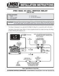
8 INSTALLATION INSTRUCTIONSFigure 4 Wiring a Single <strong>Pro</strong> <strong>Mag</strong> System.MSD IGNITION • 1490 HENRY BRENNAN DR., EL PASO, TEXAS 79936 • (915) 857-5200 • FAX (915) 857-3344
INSTALLATION INSTRUCTIONS 9Figure 5 Wiring a Dual <strong>Pro</strong> <strong>Mag</strong> System.MSD IGNITION • 1490 HENRY BRENNAN DR., EL PASO, TEXAS 79936 • (915) 857-5200 • FAX (915) 857-3344
10 INSTALLATION INSTRUCTIONSPROGRAMMINGOnce all of the wiring has been installed, connected and inspected, you should prepare to programthe Timing <strong>Controller</strong> through the Data <strong>Editor</strong>. There are no timing retards or programs built intothe units from the factory. The default is a flat timing line. You will be able to program up to 30different points within a six second time frame. The following pages will walk through setting up aprogram and files.PHASING THE PICKUPSOne thing that will need to be done prior to making a pass, is to phase the trigger pickups. Whenthe engine is started, the Data <strong>Editor</strong> will show a Message on the screen, <strong>Mag</strong>Deg 0.0°. When theengine is started, the <strong>Mag</strong>Degree message willcome onto the bottom lefton the screen (Figure 6).You will need to adjust theChannel B pickup untilthe phase difference is 0°or at least very close. ThePN 8971 will alwaystrigger off the moreretarded trigger signal. Ifthe Pickups are offset by+/-5° a Warning willdisplay on the screen.Getting StartedWhen you power On the<strong>Graphic</strong> <strong>Editor</strong>, the upperright corner will show PN7570v2 (version 2) and inthe center it will show PN8971 Timing Control andadjust to the screen. In thefuture, there will be otherproducts available for usewith the <strong>Graphic</strong> <strong>Editor</strong>and they will appear onthis opening screen.Version 2 will default tothe programming screenfor the PN 8971.Figure 6 Phasing the <strong>Mag</strong>netic Pickups.Calibrating the<strong>Graphic</strong> <strong>Editor</strong>When you power On the<strong>Graphic</strong> <strong>Editor</strong> you cancalibrate the screen. To doso touch the Adjust-Figure 7 Calibrating the <strong>Graphic</strong> <strong>Editor</strong>.Touch screen. To makeyour adjustments run your finger around the edge of the screen. Then move up, down, left or righton each edge of the impression to straighten out the border you drew with your finger. (Figure 7).To save your calibration turn off the <strong>Graphic</strong> <strong>Editor</strong>.MSD IGNITION • 1490 HENRY BRENNAN DR., EL PASO, TEXAS 79936 • (915) 857-5200 • FAX (915) 857-3344
INSTALLATION INSTRUCTIONS 11The timing chart shows six seconds going horizontally across the screen with up to 30° in .5°increments vertically on the screen. Notice that in the top left corner, it says None meaning thatthere is not a saved program open. Once you have saved files, the File Number/Name will appearhere when that file is opened. The File Name will appear in the lower left screen. Notice the verticaldotted cursor line on the timing chart. This cursor can scroll left and right throughout the six secondsof time by pressing the Left or Right button at the bottom of the screen or by touching the screenand dragging the cursor line. The values at the top of the screen will show the time and the retardamount wherever the cursor is positioned. You can also press anywhere on the timing chart tomove the cursor. When you do this, a cross hair appears to indicate the cursor position. The cursorline will remain wherever you drag it and these values will be shown above.Editing a CurvePress the Edit Curve button. Six options will come up on the screen; Select Point, Move Point,Delete Point, Add Point, Shift Curve and Move Block, then point anywhere on the screen to insertthe next point (Figure 8). Up to 30 points can be added. To move this point, select Edit Curve, thenMove Point. You can now move the point simply by pressing on the screen and draging it whereyou want or by using the move buttons at the bottom of the screen. Once moved, either pressEnter or the move will be set once there is no other movement on the screen for several seconds.Figure 8 Editing a Curve.Select or Move Point: To edit other points on a timing mag go to Edit Point and choose SelectPoint. This will allow you to pin point the exact timing point you want to modify by using the Leftand Right buttons. When the point has been determined, select Enter, then you can move thepoint Up, Down, Left or Right to move this point.Delete Point: To delete a point, select Edit Curve, then Delete Point. Choose the point you want todelete by moving the vertical cursor Left or Right. Once on the correct point, press Enter. The pointwill be deleted and the map will connect the other points.Shift Curve: If you need to move the entire curve up or down on the chart, select Shift Curve. TheUp and Down options will appear and the entire timing map will move as one up or down. Also, avalue is displayed which indicates how far the curve is being shifted from its previous position. Ifany points are at zero the timing curve cannot be shifted up further and likewise if any points are at30 degrees, the curve cannot be shifted down further.MSD IGNITION • 1490 HENRY BRENNAN DR., EL PASO, TEXAS 79936 • (915) 857-5200 • FAX (915) 857-3344
12 INSTALLATION INSTRUCTIONSNote: A ghosted image is displayed whenmoving a point or curve until the Editis completed. This shows where theedit began. To cancel an Edit youmust delete the file from the filemenu.Also, a value is displayed which indicateshow far the curve is being shifted from itsprevious position. If any points are at zerothe timing curve cannot be shifted up furtherand likewise if any points are at 30 degrees,the curve cannot be shifted down further.Move Block: If you need to move just asection of the curve up, down, left or righton the chart, select Move Block. Select theFirst point and Enter(Figure 9). Select theSecond Point and Enter (Figure 10). Now,with the up, down, left and right buttons,move the block of points you have selected,when you are done, Enter (Figure 11).Figure 9 Selecting the First Point of the Block.Edit PedalThis program is useful when the driverneeds to pedal the car. There are threesettings when programming the Edit Pedal;Pedal Degrees, Pedal Ramp and PedalInhibit (Figure 12). Once set, these valuesare shown on the second line on the top ofthe screen.When the driver lifts, you can program anamount of timing retard to occur, in additionto the <strong>Retard</strong> Curve. Select Edit Pedal, thenpress Pedal Degrees followed by Up orDown. The Pedal Edit value on the top ofthe screen will show the amount of retardand is adjusted in 0.5° increments. Whenthe driver gets back to WOT you can selectan amount of time that it takes for the timingto ramp back in. This is done through thePedal Ramp selection. Use the Up or Downbuttons to set a time in 0.01-secondincrements for up to 2.5-seconds.Figure 10 Selecting the Second of the Block.The last Edit Pedal function is Inhibit. Thisallows you to select an amount of time thatwill inhibit the Pedal <strong>Retard</strong> function. You canprogram this for up to 2.5 seconds in 0.01-second increments. This way, no pedal retardor ramp times will occur until the Inhibit timehas elapsed from the launch.Figure 11 Moving the BlockMSD IGNITION • 1490 HENRY BRENNAN DR., EL PASO, TEXAS 79936 • (915) 857-5200 • FAX (915) 857-3344
INSTALLATION INSTRUCTIONS 13Match CurveThis function can be used to view twodifferent file curves and allows the user totoggle which one of the two curves canbe edited. To edit a curve using a referencecurve on the 7570 screen, select thematch curve function (Figure 13). Thenselect a file# which will appear in aghosted form on the screen. The ghostcurve cannot be edited, only the dark curvecan be edited. Perform normal edits. Tochange which curve can be edited use thetoggle curve button (Figure 13).To exit the Match Curve function selectMatch Curve and then select Match Off.Save and Transfer a CurveOnce you have a timing map created youcan save it on the <strong>Graphic</strong> <strong>Editor</strong>. It willsave up to 12 maps (Figure 15). Select File,and Save, 1 through Save 6 will appear.Choose a file and press write File tocomplete the Save (Figure 16). To call aSaved File to the screen, select File, thenpress one of the # to Screen icons.To transfer a file from the 7570 to the 8971first retrieve the file from memory from the<strong>Graphic</strong> <strong>Editor</strong>. Press the File button andselect the appropriate File# To Screenbutton. Once you have the File you wanton the screen, you have to transfer it tothe Timing <strong>Controller</strong>. To send it to theTiming <strong>Controller</strong> (which must bepowered On and connected to the<strong>Graphic</strong> <strong>Editor</strong>, select the Send Plot thenPress to MSD (Figure 17). The upper leftcorner of the screen will display MSDindicating that the screen data nowmatches the program of the Timing<strong>Controller</strong>. The lower left line of themessage line will display Verify OK,meaning that both channels of the Timing<strong>Controller</strong> received the program.Figure 12 Setting the Pedal Lift Options.Figure 13 Match Curve Options.Figure 14 Match Curve Options.MSD IGNITION • 1490 HENRY BRENNAN DR., EL PASO, TEXAS 79936 • (915) 857-5200 • FAX (915) 857-3344
14 INSTALLATION INSTRUCTIONSIf there is a problem with thetransfer, an Alert message willbe displayed on the lower rightof the screen. Either No ReplyA, No Reply B or Verify Errorwould indicate a problem.These will generally indicate aproblem within the cable or thatpower to the <strong>Controller</strong> was notmaintained. The file could havebeen corrupted during thetransfer due to a failingconnection, electronicinterference or a low battery.Check for any of theseconditions and attempt thetransfer again.A file can also be sent to a PCwhere it can be viewed, editedand saved along with notesFigure 15 Open and Save a Curve.about the run. This is donethrough the MSD Graph Save software (supplied with the <strong>Graphic</strong> <strong>Editor</strong>, PN 7570V2), version 1.04or later. This allows you to create and edit files with all of the same functions of the <strong>Graphic</strong> <strong>Editor</strong> onyour PC. The files can also be saved in your PC and sent to the <strong>Graphic</strong> <strong>Editor</strong>. The software isdesigned for use with most Windows operating systems such as 95, 98, 2000, XP, NT or ME. Totransfer a file to your PC, connect the RS232 cable to the ‘To PC’ outlet on the PN 7570 and to yourPC. (The Timing <strong>Controller</strong> and PC cannot be connected at the same time.)To send a file to the PC, the file must be on the screen of the <strong>Graphic</strong> <strong>Editor</strong>. Press the Send Plotbutton, and select To PC. Once the timing map appears on the PC, you can edit it or save it to thehard drive. If you want totransfer a file from the PC to the<strong>Graphic</strong> <strong>Editor</strong>, (the file must beopen on the PC), select SendPlot on the <strong>Editor</strong> then press PCto Screen. The Help file of theMSD GraphSave software isuseful in learning how tomanipulate timing map files onthe PC. The PC to File allowsyou to transfer multiple filesfrom the PC to the desired filenumber in the 7570 <strong>Editor</strong>.Note: After a PC to Screen issent from the PC to the<strong>Graphic</strong> Editior it isrecommended to save itto a File Number (1-12)before sending it to thecontroller.Figure 16 Save a File options.MSD IGNITION • 1490 HENRY BRENNAN DR., EL PASO, TEXAS 79936 • (915) 857-5200 • FAX (915) 857-3344
INSTALLATION INSTRUCTIONS 15Figure 17 Sending the Timing Map.Checking the InformationThe <strong>Graphic</strong> <strong>Editor</strong> allows you to verify that the data on the screen is the same data that is loadedin the Timing <strong>Controller</strong>. With the two units connected and powered on, press the Check Buttonfollowed by Verify Move (Figure 18). The <strong>Editor</strong> will verify that the last operation (whether it be asave, send or transfer) was successful and the data matches. An Alert will show on the screen ifthere was no reply or problem.The Check button also gives you two other options, Reset <strong>Mag</strong>Cnt. This resets the <strong>Mag</strong>netic PickupCount. During each run, the Timing <strong>Controller</strong> counts any missed triggers. This information isdisplayed as a message and will read Mis<strong>Mag</strong>A or Mis<strong>Mag</strong>B 0-255. To reset the count, push Check,then Reset <strong>Mag</strong>Cnt. The second option is the Isolate <strong>Mag</strong> A/B. This will allow you to check andcompare the actual timingbetween each generator, witha timing Light.Note: In order to reset theIsolate <strong>Mag</strong> A/B, thepower to the unit mustbe turned off, then backon, or the engine shutoff.Figure 18 Confirming your Changes.MSD IGNITION • 1490 HENRY BRENNAN DR., EL PASO, TEXAS 79936 • (915) 857-5200 • FAX (915) 857-3344
TECH NOTES________________________________________________________________________________________________________________________________________________________________________________________________________________________________________________________________________________________________________________________________________________________________________________________________________________________________________________________________________________________________________________________________________________________________________________________________________________________________________________________________________________________________________________________________________________________________________________________________________________________________________________________________________________________________________________________________________________________________________________________________________________________________________________________________________________________________________________________________________________________________________________________________________________________________________________________________________________________________________________________________________________________________________________________________________________________________________________________________________________________________________________________________________________________________________________________________________________________________________________________________________________________________________________________________________________________________________________________________________________________________________________________________________________________________________________________________________________________________________________________________ServiceIn case of malfunction, this MSD component will be repaired free of charge according to the terms ofthe warranty. When returning MSD components for service, <strong>Pro</strong>of of Purchase must be supplied for warrantyverification. After the warranty period has expired, repair service is charged based on a minimum andmaximum charge.Send the unit prepaid with proof of purchase to the attention of: Customer Service Department, MSDIgnition, 12120 Esther Lama, Suite 114, El Paso, Texas 79936.When returning the unit for repair, leave all wires at the length in which you have them installed. Be sureto include a detailed account of any problems experienced, and what components and accessories areinstalled on the vehicle.The repaired unit will be returned as soon as possible after receipt, COD for any charges. (Groundshipping is covered by warranty). All units are returned regular UPS unless otherwise noted. For moreinformation, call the MSD Customer Service Line (915) 855-7123. MSD technicians are available from 8:00a.m. to 5:00 p.m. Monday - Friday (mountain time).Limited WarrantyMSD IGNITION warrants MSD Ignition products to be free from defects in material and workmanshipunder normal use and if properly installed for a period of one year from date of purchase. If found to bedefective as mentioned above, it will be replaced or repaired if returned prepaid along with proof of dateof purchase. This shall constitute the sole remedy of the purchaser and the sole liability of MSD Ignition. Tothe extent permitted by law, the foregoing is exclusive and in lieu of all other warranties or representationswhether expressed or implied, including any implied warranty of merchantability or fitness. In no eventshall MSD Ignition be liable for special or consequential damages.MSD IGNITION • 1490 HENRY BRENNAN DR., EL PASO, TEXAS 79936 • (915) 857-5200 • FAX (915) 857-3344FRM26504 Revised 1/05 Printed In U.S.A.