EL In-Place Inclinometer - Slope Indicator
EL In-Place Inclinometer - Slope Indicator
EL In-Place Inclinometer - Slope Indicator

You also want an ePaper? Increase the reach of your titles
YUMPU automatically turns print PDFs into web optimized ePapers that Google loves.
<strong>EL</strong> <strong>In</strong>-<strong>Place</strong><strong>In</strong>clinometer56804199Copyright ©2006 Durham Geo <strong>Slope</strong> <strong>In</strong>dicator. All Rights Reserved.This equipment should be installed, maintained, and operated by technically qualified personnel. Any errorsor omissions in data, or the interpretation of data, are not the responsibility of <strong>Slope</strong> <strong>In</strong>dicator Company. Theinformation herein is subject to change without notification.This document contains information that is proprietary to <strong>Slope</strong> <strong>In</strong>dicator company and is subject to returnupon request. It is transmitted for the sole purpose of aiding the transaction of business between <strong>Slope</strong> <strong>In</strong>dicatorCompany and the recipient. All information, data, designs, and drawings contained herein are proprietaryto and the property of <strong>Slope</strong> <strong>In</strong>dicator Company, and may not be reproduced or copied in any form, byphotocopy or any other means, including disclosure to outside parties, directly or indirectly, without permissionin writing from <strong>Slope</strong> <strong>In</strong>dicator Company.SLOPE INDICATOR12123 Harbour Reach DriveMukilteo, Washington, USA, 98275Tel: 425-493-6200 Fax: 425-493-6250E-mail: solutions@slope.comWebsite: www.slopeindicator.com
Contents<strong>In</strong>troduction. . . . . . . . . . . . . . . . . . . . . . . 1Pre-Assembly . . . . . . . . . . . . . . . . . . . . . 5Vertical <strong>In</strong>stallation . . . . . . . . . . . . . . . . 6Horizontal <strong>In</strong>stallation . . . . . . . . . . . . .11Manual Reading . . . . . . . . . . . . . . . . . . 14Data Logging. . . . . . . . . . . . . . . . . . . . . .16Data Reduction. . . . . . . . . . . . . . . . . . . .18Removing Sensors. . . . . . . . . . . . . . . . .23<strong>EL</strong> <strong>In</strong>-<strong>Place</strong> <strong>In</strong>clinometer, 2008/7/09
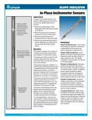
<strong>In</strong>troduction<strong>In</strong>-<strong>Place</strong><strong>In</strong>clinometersExpected Directionof Movement<strong>In</strong> vertical installations, onepair of casing grooves shouldbe aligned with the expecteddirection of movement.VerticalThe in-place inclinometer system consists ofinclinometer casing and a string of linkedin-place inclinometer sensors.The inclinometer casing provides access for subsurfacemeasurements, controls the orientation ofthe sensors, and moves with the surroundingground.<strong>In</strong> vertical installations, the inclinometer casing isinstalled in a borehole that passes through a suspectedzone of movement. One set of grooves isaligned in the expected direction of movement(downhill, for example).<strong>In</strong> horizontal installations, inclinometer casing istypically installed in a trench. One set of groovesmust be aligned to vertical, since the instrument isexpected to monitor vertical movements (settlementor heave).The string of linked sensors is positioned insidethe casing to span the zone of movement. Whenthe ground moves, the casing moves with it,changing the inclination of the sensors inside thecasing.Fixed wheelpoints atdirection ofmovementin verticalinstallationsCasingcontrolsorientationof sensorsSensorgaugelength<strong>In</strong> horizontal installations, onepair of casing grooves must bealigned to vertical.Sensors for vertical installations measure inclination from vertical. Sensorsfor horizontal installations measure inclination from horizontal.<strong>In</strong>clination measurements from the sensors are processed to providedisplacement readings in mm of displacement for the gauge length ofeach sensor.<strong>In</strong> most applications, sensors are connected to a data acquisition systemand data processing is completed by a computer program.<strong>In</strong>clinometer casing controls the orientation of the sensorFixed wheel points downin horizontal installationsSensor gauge length<strong>EL</strong> <strong>In</strong>-<strong>Place</strong> <strong>In</strong>clinometer, 2008/7/09 1
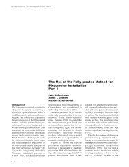
IPI SensorComponentsIPI sensor with wheelassembly and top andbottom tubing clamps.Each sensor has a serialnumber and is suppliedwith a specifiedlength of signal cable.Fixed wheel isimportant atinstallationtime.Tubing clamp connectssensor to gauge tubingGauge tubing completes thegauge length of the sensorbelow. Typically longer thanshown here.Tubing clamp connects thesensor to the gauge tubing.Fixed wheel isimportant atinstallationtime.Bottom IPI sensorincludes a swivel clampto lock the bottomwheel assembly.<strong>EL</strong> <strong>In</strong>-<strong>Place</strong> <strong>In</strong>clinometer, 2008/7/09 2
Other ComponentsSuspension Kit includes wheelassembly and hardware to clampand adjust suspension cable.Suspension kit is used with verticalinclinometers. Stainless cable isrequired, but not shown.<strong>Place</strong>ment Kit includeswheel assembly and topclamp. Clamp rests on top ofcasing and hold placementtubing in center of casing.<strong>Place</strong>ment kit is typicallyused with horizontal IPIinstallations, but can also beused for vertical installations.Coupling for placementtubing.<strong>Place</strong>ment tubing is usedto push inclinometer intoposition and then keep itthere. Generally suppliedin 10 ft. or 3 meterlength.<strong>EL</strong> <strong>In</strong>-<strong>Place</strong> <strong>In</strong>clinometer, 2008/7/09 3
Gauge TubingGauge tubing is typically ordered with the sensors. If gauge tubing isnot supplied, check project specifications for required gauge length,and then follow the instructions below:1. Choose stainless tubing that can accept tubing clamps. The standardtubing clamps have a minimum OD of 15.6 mm (0.615 inch) andexpand to a maximum OD of 17.4 mm (0.685 inch).2. Measure and mark the gauge tubing for the proper length:tubing length = total gauge length – 550 mm (21.625 inch).For example, you would cut tubing lengths of 1450 mm for a totalgauge length of 2 meters.3. Cut and deburr the gauge tubing. Check that tubing clamps fit inside.Suspension Cable<strong>Place</strong>ment TubingSuspension cable, if used, is typically ordered with the system. The suspensionkit contains hardware for 3/16 inch cable. The cable is 3/16inch, 19 x 7, stainless steel aircraft cable.<strong>Place</strong>ment tubing, if used, is typically ordered with the system. If placementtubing is required, but not supplied, follow the instructions below.1. Choose stainless tubing that can accept tubing clamps and couplings.The standard tubing clamps have a minimum OD of 15.6 mm (0.615inch) and expand to a maximum OD of 17.4 mm (0.685 inch).2. Deburr the gauge tubing and check that tubing clamps fit inside.3. Use the coupling shown on previous page to join lengths of placementtubing.4. Use in-line wheel assembly if placement tubing must be articulated.Safety Cable<strong>In</strong> vertical installations, you may find it useful to connect a safety cableto the bottom sensor to prevent accidental loss of the sensors.<strong>EL</strong> <strong>In</strong>-<strong>Place</strong> <strong>In</strong>clinometer, 2008/7/09 4
Pre-Assembly<strong>In</strong>troductionToolsIdentify andCheck SensorsAttach Gauge Tubingto Each SensorThis chapter tells how to connect gauge tubing to the sensors. We donot recommend further pre-assembly. Sensors should be joined toother sensors only as they are installed downhole.• Vice-grips to hold gauge tubing.• Wrench to tighten tubing clamps.• Test each sensor. See “Manual Readings” for instructions.• Write down the serial number and intended installation depth ofeach sensor.• Check that wheels are firmly attached to sensors.Also check that the swivel clamp isattached to the wheel assembly of the bottom(farthest) sensor.• Check that cable lengths are correct and attachsensor ID tags to ends of signal cables.• Mark sensors for order of installation.Swivelclamp onbottomsensorAs you work, be careful not to bend or damage the wheel assembly asyou work.1. Remove the tubing clamp from the top of the sensor body.2. <strong>In</strong>sert clamp into gauge tubing3. Hold tubing and tighten clamp well.4. Screw gauge tubing onto sensor body until sensor body and gaugetubing form a rigid unit.1 2 3 4<strong>EL</strong> <strong>In</strong>-<strong>Place</strong> <strong>In</strong>clinometer, 2008/7/09 5
Vertical <strong>In</strong>stallationOverview1. Lay out sensors in order of installation.2. <strong>In</strong>sert the first sensor in the preferred set of grooves. The fixed wheelshould point toward the expected direction of movement.3. Lower the sensor into the casing. Keep the top of the gauge tubeaccessible.4. Align the next sensor with the preferred set of grooves as in step 2,and connect it to the gauge tubing of the downhole sensor.5. Lower the sensors into the casing. Repeat steps 4 and 5 until all sensorshave been installed.6. Prepare the suspension kit or the placement kit.7. Lower the sensors to their final location and terminate the top.Required ToolsPreparations• Safety cable attached to bottom sensor to prevent loss of sensorsdown hole.• Vice grips (clamping pliers) for holding gauge tubing whileconnecting adjacent sensors.• Thin 17 mm wrench for tightening tubing clamps.• Tools for cable clamps or Allen wrench for securing top clamp.• Vinyl tape for securing cable to gauge tubing.1. Note serial number and position of each sensor.2. Lay out sensors in order of installation. We do not recommend preassemblyof the string of sensors. Add sensors to the string one byone as you install them downhole.3. Keep cables coiled until sensor is installed.RemovalIf it is necessary to remove sensors, take the following precautions:• Never try to remove the assembled string of sensors. The weight andleverage of long gauge lengths make it very easy to damage thewheels.• Always disassemble the string, sensor by sensor. When removingeach sensor, always clamp the gauge tubing of the downhole sensor toprevent it from twisting.<strong>EL</strong> <strong>In</strong>-<strong>Place</strong> <strong>In</strong>clinometer, 2008/7/09 6
<strong>In</strong>stall theBottom Sensor1. Attach safety line (nylon or wire rope) tobottom sensor. Secure the safety line.2. <strong>In</strong>sert first (bottom) sensor in preferred setof grooves. The fixed wheel should point tothe expected direction of movement. Checkthat the wheel has a swivel clamp.FixedWheelSwivelClamp3. Lower sensor into casing. Tape signal cable to gauge tubing.Use vice grips to clamp top of gauge tubing. Now the next sensor canbe installed.Tape signal cable to gauge tubing.Tie a safety line (nylonor wire rope) to thebottom sensor.Clamp gaugetubing withvice grip.Fixed wheel shouldpoint to expecteddirection of movement.<strong>In</strong>clinometerCasing<strong>EL</strong> <strong>In</strong>-<strong>Place</strong> <strong>In</strong>clinometer, 2008/7/09 7
<strong>In</strong>stall Next SensorConnect next sensor to the gauge tubing of the sensor below, as shownin the drawing. Continue adding sensors until the sensor string is complete.Keep the following points in mind:• Do not allow the installed sensor to twist in the casing when youtighten the connection. Twisting can damage the wheels or pop themout of the grooves.• When you lower the sensor into the casing, check that the fixedwheel is aligned in the proper direction.• Tape cables neatly, so that they do not cross each other.Tape cablesneatly foreasierinstallation.Check that fixedwheel is aligned withproper groove.Tighten tubingclamp well.Hold gaugetubing firmlyso that it doesnot twist.<strong>EL</strong> <strong>In</strong>-<strong>Place</strong> <strong>In</strong>clinometer, 2008/7/09 8
<strong>In</strong>stall Top WheelAttach top wheel from suspension kit or placement kit.• Suspension kit: Wheel supplied in suspension kit has an eyelet forsuspension cable. Connect suspension cable as shown in drawing.• <strong>Place</strong>ment kit: Wheel supplied in placement kit has tubing clamp.Attach placement tubing as shown in the drawing.SuspensionCable<strong>Place</strong>mentTubingCheck alignment offixed wheel and donot twist gauge tubewhen tightening nuts.<strong>EL</strong> <strong>In</strong>-<strong>Place</strong> <strong>In</strong>clinometer, 2008/7/09 9
Terminatewith Suspension KitThe suspension kit is used with verticalinstallations. It consists of a top wheelassembly, shown on the previous page,cable thimbles, cable clamps, and ahook for the top of the casing.1. Cut the suspension cable to theappro-priate length.2. Attach the cable to the top wheelassembly using the thimble andclamps.Cablethimble3. Attach the other end of the cable tothe chain, as shown in the drawing.4. Use the chain is used to adjust thefinal depth of the sensors.Terminate with<strong>Place</strong>ment KitThe placement kit is sometimes usedwith vertical installations. It consists ofa top wheel assembly, shown on theprevious page, and a “top” clamp forplacement tube.The top clamp holds either placementtubing - when the sensors are deeper inthe casing - or the gauge tube of thenearest sensor.The top clamp has a split collar. Loosenthe screws, slide the collar over theplacement tubing or gauge tubing, andthen tighten the screws.<strong>EL</strong> <strong>In</strong>-<strong>Place</strong> <strong>In</strong>clinometer, 2008/7/09 10
Horizontal <strong>In</strong>stallationOverview1. Lay out sensors in order of installation.2. Align the first sensor with the vertical grooves of the casing. <strong>In</strong>sertthe sensor with its fixed wheel pointing downwards.3. Push the sensor into the casing. Keep the top end of its gauge tubingaccessible.4. Connect the next sensor to the gauge tubing of the downhole sensor.Then push it into the casing.5. Continue connecting sensors until the string is complete.6. Connect the final wheel assembly.7. Prepare the placement kit and placement tubing.8. Push push sensors to final location and terminate.Required ToolsPreparations• Safety cable may be useful if sensors are to be retrieved or if casingactually slopes downwards.• Vice grips (clamping pliers) for holding gauge tubing whileconnecting adjacent sensors.• Thin 17 mm wrench for tightening tubing clamps.• Allen wrench for securing top clamp.• Vinyl tape for securing cable to gauge tubing.1. Attach gauge tubing to each sensor, as explained previously. We donot recommend joining sensors together now. Add sensors one byone to the string.2. Lay out sensors in order of installation. Note the serial number andposition of each sensor.3. Keep cables coiled until sensor is installed.RemovalIf it is necessary to remove sensors, take the following precautions:• Never try to remove the assembled string of sensors. The weight andleverage of long gauge lengths make it very easy to damage thewheels.4. Always disassemble the string, sensor by sensor. When removingeach sensor, always clamp the gauge tubing of the downhole sensorto prevent it from twisting.<strong>EL</strong> <strong>In</strong>-<strong>Place</strong> <strong>In</strong>clinometer, 2008/7/09 11
<strong>In</strong>stall theFirst Sensor1. Check that the first sensor has a swivel clamp on its wheel assembly.2. Tape signal cable to the gauge tubing.3. Align the fixed wheel with the bottom groove and push the sensorinto the casing.Swivel ClampFixed Wheel<strong>In</strong>stall More Sensors1. Prepare to connect the next sensor. Align the fixed wheel with thebottom groove.2. Push the tubing clamp into the gauge tubing of the sensor that isalready in the casing. Do not twist the gauge tubing when you tightenthe tubing clamp nuts.Do not twist gauge tubing.FixedWheelTubingClamp3. Continue adding sensors until the sensor string is complete.:Keep cable away from wheels.Allow some slack at the swivel.Arrange cables neatly so that theydo not cross. Ideally, cables shouldnot touch casing.• Do not twist the installed sensor when you tighten tubing clamps.Twisting can damage the wheels or pop them out of the grooves.• Always verify that the fixed wheel is in the bottom groove.• Tie cables neatly, so that they do not cross each other.<strong>EL</strong> <strong>In</strong>-<strong>Place</strong> <strong>In</strong>clinometer, 2008/7/09 12
Terminating the<strong>In</strong>stallationThe placement kit supplies most of the components used to terminatehorizontal installations. The placement kit includes a top wheel assemblyand a top clamp. A top clamp retainer is also available.<strong>In</strong>stall Top WheelThe top wheel completesthe gauge lengthof the nearest sensor.Align the fixed wheelwith the bottomgroove.Do not twist the sensors whenyou tighten the tubing clamp.The top wheel is not required if the gauge length of the top sensor is terminatedwith the top clamp.<strong>In</strong>stall<strong>Place</strong>ment Tubing<strong>Place</strong>ment tubing is used to position the sensors deeper into the casing.<strong>Place</strong>ment tubing is normally longer than shown in the illustration. Acoupling is used to join two placement tubes.Do not twist the sensors when youtighten the tubing clamp.<strong>In</strong>stallTop ClampThe top clamp holds placement tubing or the gauge tube of the nearestsensor.1. The top clamp has a split collar.Loosen the screws, slide the collar overthe placement tubing or gauge tubing,and then tighten the screw.2. (Optional) Use the top clamp retainerto hold the top clamp to the casing.TopclampretainerTopclamp3. <strong>In</strong> horizontal installations, the sensors normally must be pushed intothe casing. This puts the mechanical linkage of the sensors into compression.If possible, put the linkage into tension, but pushing thesensors deeper into the casing and then pulling them back intoposition.<strong>EL</strong> <strong>In</strong>-<strong>Place</strong> <strong>In</strong>clinometer, 2008/7/09 13
Manual Readings<strong>In</strong>troduction<strong>EL</strong> Data RecorderManual readings are useful for testing the system before the data acquisitionsystem is set up. This manual covers connections to IPI sensorsthat have a 2.5v signal conditioner. Previous signal conditioners used a250 mV signal conditioner with different wiring.1. Connect sensor to readout as shown in the table below.2. Switch on. Choose uniaxial or biaxial sensor.3. Tilt is displayed in volts. Temperature is displayed in degrees C.Data Recorder TerminalSignal Cable Wire1 Tilt A Orange2 Tilt B Blue3 Temp Red4 Sig Common Yellow5 Sense Violet6 Power + Green7 Power - Black8 Shield Drain WireTesting witha VoltmeterThe voltmeter should be capable of displaying values in the low millivoltdc range. You must also have a power source must supply between5.5 and 15 Vdc. An alkaline 9-volt battery is suitable1. Connect green wire to the + terminal of the power source. Connectthe violet wire and black wire to the - terminal of the power source.2. To read the A-axis sensor, connect the voltmeter to the orange wire(signal) and yellow wire (reference).3. To read the B-axis sensor, connect the voltmeter to the blue wire (signal)and yellow wire (reference).4. To read the thermistor, connect the voltmeter to the red and yellowwires.<strong>EL</strong> <strong>In</strong>-<strong>Place</strong> <strong>In</strong>clinometer, 2008/7/09 14
Test Readings1. When the sensor body is vertical, you should see a reading of about0.0 Vdc.2. The A-axis sensor measures tilt in the plane of the wheels. Tilt the topof the sensor in the direction of the fixed wheel. The reading shouldbe about 2.2 to 2.3 V as the tilt nears 10 degrees. Tilt the top of thesensor in the direction of the sprung wheel. The reading should beabout -2.2 to -2.3 V as the tilt nears 10 degrees.3. The B-axis sensor (available with biaxial sensors only) is rotated 90degrees from the A-axis sensor. Tilting the sensor to 10 degreesshould provide a reading of ±2.2 to 2.3 Volts.4. See the next section, data reduction, to learn how to convert thereading in volts to deviation in mm.5. At 25 degrees C, the thermistor reading should be about 1 Vdc.<strong>EL</strong> <strong>In</strong>-<strong>Place</strong> <strong>In</strong>clinometer, 2008/7/09 15
DataLoggingData Loggingwith CR10XWiring Diagram 1These instructions provide information needed for reading uniaxialand biaxial IPIs with the Campbell Scientific CR10X datalogger system.Sample Program: A sample CR10X monitoring program is available at<strong>Slope</strong> <strong>In</strong>dicator’s website. Go to www.slopeindicator.com - support -tech notes. Look at the data logger technotes. You’ll see a link for sampleprograms.Wiring Diagrams: The wiring g diagrams on the following pages showhow to connect uniaxial and biaxial IPIs to the Campbell ScientificCR10X datalogger system.Connecting a uniaxial sensor directly to the CR10XWiring Diagram 2Connecting a biaxial sensor directly to CR10X<strong>EL</strong> <strong>In</strong>-<strong>Place</strong> <strong>In</strong>clinometer, 2008/7/09 16
Wiring Diagram 3Connecting uniaxial sensors to an AM416 multiplexerWiring Diagram 4Connecting biaxial sensors to an AM416 multiplexer<strong>EL</strong> <strong>In</strong>-<strong>Place</strong> <strong>In</strong>clinometer, 2008/7/09 17
Data Reduction<strong>In</strong>troductionData reduction is usually automated because it involves a large numberof readings and a large number of calculations.Here, we explain how to use the sensor calibration record and providean example of converting a single reading from voltage to mm of deviationand mm of displacement.Calibration RecordA calibration record is provided with each <strong>EL</strong> IPI sensor. Note that calibrationsare unique for each sensor, so use sensor serial numbers tomatch sensors with their calibrations.The sensor calibration record lists three setsof factors for each axis of the sensor andone factor for the temperature sensor. Thetable at right shows factors for sensor serialnumber 10001. Your sensors will have differentfactors.C0 to C5: Use these factors to convert areading in volts to mm per meter of gaugelength.S0 to S2: Use these factors if it is necessaryto adjust the mm/m value above for temperature-relatedchanges in sensor sensitivity.F0 to F2: Use these factors if it is necessaryto adjust the mm/meter value for temperature-relatedchanges in the offset of the sensor.Toffset: Use this factor in the equation toconvert a thermistor reading in volts todegrees C.C0 -7.0311C1 73.878C2 -0.22265C3 -0.33079C4 0.019426C5 0.020221S0 1S1 0.00059828S2 0.0000068117F0 00012125F1 0.016273F2 0.00096919Toffset 0.19Tnom 12Tnom: Tnom is normally 12 degrees C.However, the value shown on the sensor calibration record may behigher or lower if your sensors were calibrated over a custom range oftemperatures.<strong>EL</strong> <strong>In</strong>-<strong>Place</strong> <strong>In</strong>clinometer, 2008/7/09 18
ApplyingCalibration FactorsConvertingsensor readingsto mm per meterSuppose you obtain a reading of 0.57V from sensor 10001, which has agauge length of 2 meters. How do you convert the voltage reading tomm of deviation?Apply the C factors to the voltage reading as shown below. <strong>EL</strong> representsa reading in volts. C5 through C0 are factors that appear on thesensor calibration record. The result of the calculation is a value in mmper meter.mm/meter = C5 • <strong>EL</strong> 5 + C4 • <strong>EL</strong> 4 + C3 • <strong>EL</strong> 3 + C2 • <strong>EL</strong> 2 + C1 • <strong>EL</strong> + C0C Factor <strong>EL</strong> Reading ValueC0 -7.0311 -70311C1 73.878 0.57 42.11046C2 -0.22265 0.572 -0.07234C3 -0.33079 0.573 -0.06126C4 0.19426 0.574 0.002051C5 0.020221 0.575 0.001217mm per meter deviation = 34.94903CalculatingDeviationTo calculate deviation for a particular gauge, multiply themm/meter value by the gauge length of the sensor. <strong>In</strong> this example, thegauge length is 2 meters, so the deviation would be 2 x 34.949 mm orabout 70 mm.deviation in mm = mm per meter value • gauge length of sensor in meters<strong>In</strong> this example, the gauge length is 2 meters, so the deviation would be2 x 34.949 mm or about 70 mm.CalculatingDisplacementDisplacement (movement) is the change in deviation. The next pageshows the direction of movement associated with negative and positivedisplacement values.displacement = deviation current - deviation initial<strong>EL</strong> <strong>In</strong>-<strong>Place</strong> <strong>In</strong>clinometer, 2008/7/09 19
Direction ofMovementfor Vertical IPIs<strong>In</strong>clinometer casing is typically installed so that one set of grooves isparallel with the expected direction of movement. Sensors are installedso that their fixed wheels point to the direction of movement.When the bottom of the casing or the bottom of the sensor is used asreference, positive displacement values indicate movement in the directionof the fixed wheels (normally the expected direction).A positive displacementvalue for the A axis indicatesmovement in the direction ofthe fixed wheels.+ –A negative displacementvalue in the A axis indicatesmovement in the directionof the sprung wheels.Displacements are referencedto the bottom of the casingor the bottom of the sensor.<strong>EL</strong> <strong>In</strong>-<strong>Place</strong> <strong>In</strong>clinometer, 2008/7/09 20
Direction ofMovementHorizontal SensorFar-End ReferenceHorizontal inclinometer casing must be installed with one set ofgrooves oriented to the vertical. Sensors are installed with the fixedwheel pointing down.When the far end of the casing or the far end of the sensor is used as thereference, negative displacements indicate upward movement and positivedisplacements indicate downward movement:A negative displacementvalue indicates movementin the direction of thesprung wheels.–Far end of casing orfar end of sensor usedas reference.+A positive displacementvalue indicates movementin the direction of the fixedwheels.Near-End ReferenceWhen the near end of the casing or the near end of the sensor is used asthe reference, negative displacements indicate downward movementand positive displacements indicate upward movement:A positive displacementvalue indicates movementin the direction of thesprung wheel.+Near end of casing ornear end of sensorused as reference.–A negative displacementvalue indicates movementin the direction thefixed wheel.<strong>EL</strong> <strong>In</strong>-<strong>Place</strong> <strong>In</strong>clinometer, 2008/7/09 21
TemperatureReadingsThe CR10 delivers thermistor readings in volts. The equation belowshows how to convert the volt reading to degrees C. The factors in theequation are optimized for temperatures between -15 and 85 degrees C.ET is the volt reading. Toffset is taken from the sensor calibration sheet.DegC = ( 9.3219 x ET 5 ) + ( -54.3038 x ET 4 ) + ( 131.165 x ET 3 ) + ( -161.2568 x ET 2 ) + ( 137.7711 x ET ) + ( -37.7705 ) - ToffsetTemperatureCorrectionsIf the temperature of the sensors remains relatively constant, as is thecase for most underground applications, temperature corrections maynot be useful. However, if the sensors experience wide variations intemperatures, temperature corrections may be necessary. There are twocorrections: a sensitivity correction called SENSTC and an offsetcorrection OFFSTC.1. Find the change in temperature from Tnom, which is a value on thesensor calibration sheet.DeltaT = DegC - TnomExample: DegC is 19.3 and Tnom is 12 degrees C,so DeltaT, the change in temperature, is 7.3 degrees C2. Calculate the sensitivity correction:SENSTC = S2•DeltaT 2 + S1•DeltaT + S0S Factor DeltaT ValueS0 1 1S1 0.00059828 7.3 0.004367S2 0.0000068117 7.3 2 0.000363SENSTC = 1.004733. Calculate the offset correction:OFFSTC = F2•DeltaT 2 + F1•DeltaT + F0F Factor DeltaT ValueF0 0.00012125 .000121F1 0.016273 7.3 0.118793F2 0.00096919 7.3 2 0.051648OFFSTC = 0.1705624. Apply the corrections:corrected value = ( mm/meter value • SENSTC ) + OFFSTC= ( 34.94903 • 1.00473 ) + 0.170562= 35.28491<strong>EL</strong> <strong>In</strong>-<strong>Place</strong> <strong>In</strong>clinometer, 2008/7/09 22
Removing SensorsRemoval of SensorsIf it is necessary to remove sensors, take the following precautions:• Never try to remove the assembled string of sensors. The weight andleverage of long gauge lengths make it very easy to damage thewheels.• You must disassemble the string as you withdraw it, so that you actuallyremove sensors one by one. When removing each sensor, alwaysclamp the gauge tubing of the downhole sensor to prevent it fromtwisting.<strong>EL</strong> <strong>In</strong>-<strong>Place</strong> <strong>In</strong>clinometer, 2008/7/09 23