contreras-grout-in-p.. - Slope Indicator
contreras-grout-in-p.. - Slope Indicator
contreras-grout-in-p.. - Slope Indicator
- No tags were found...

You also want an ePaper? Increase the reach of your titles
YUMPU automatically turns print PDFs into web optimized ePapers that Google loves.
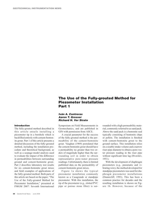
GEOTECHNICAL INSTRUMENTATION NEWSThe Use of the Fully-<strong>grout</strong>ed Method forPiezometer InstallationPart 1Iván A. ContrerasAaron T. GrosserRichard H. Ver StrateIntroductionThe fully-<strong>grout</strong>ed method described <strong>in</strong>this article entails <strong>in</strong>stall<strong>in</strong>g apiezometer tip <strong>in</strong> a borehole which isbackfilled entirely with cement-bentonite<strong>grout</strong>. Part 1 of this article presents adetailed discussion of the fully-<strong>grout</strong>edmethod, <strong>in</strong>clud<strong>in</strong>g the <strong>in</strong>stallation procedureand theoretical background, aswell as a seepage-model analysis usedto evaluate the impact of the difference<strong>in</strong> permeabilities between surround<strong>in</strong>gground and cement-bentonite <strong>grout</strong>.Part 2 describes laboratory test resultsfor six cement-bentonite <strong>grout</strong> mixesand field examples of applications ofthe fully-<strong>grout</strong>ed method. Both parts ofthis article are based on the paper, “TheUse of the Fully-<strong>grout</strong>ed Method forPiezometer Installation,” presented atFMGM 2007: Seventh InternationalSymposium on Field Measurements <strong>in</strong>Geomechanics, and are published <strong>in</strong>GIN with permission from ASCE.A crucial parameter for the successof the fully-<strong>grout</strong>ed method is the permeabilityof the cement-bentonite<strong>grout</strong>. Vaughan (1969) postulated thatthe cement-bentonite <strong>grout</strong> should havea permeability no greater than two ordersof magnitude higher than the surround<strong>in</strong>gsoil <strong>in</strong> order to obta<strong>in</strong>representative pore-water pressureread<strong>in</strong>gs. Unfortunately, there is limitedpublished data on the permeability ofcement-bentonite <strong>grout</strong> mixes.Figure 1a shows the typicalpiezometer <strong>in</strong>stallation commonlyknown as a Casagrande or standpipepiezometer. With this <strong>in</strong>stallation, thetip of the piezometer (e.g., slotted PVCpipe or porous stone filter) is surroundedwith a high permeability material,commonly referred to as sand pack.Above the sand pack is a bentonite sealtypically consist<strong>in</strong>g of bentonite chipsor pellets. The <strong>in</strong>stallation is f<strong>in</strong>ishedwith cement-bentonite <strong>grout</strong> to theground surface. This <strong>in</strong>stallation relieson a sizable <strong>in</strong>take volume and a narrowriser-pipe diameter to obta<strong>in</strong> a pore-waterpressure read<strong>in</strong>g <strong>in</strong> the riser pipewithout significant time lag (Hvorslev,1951).With the development of diaphragmpiezometers (e.g., pneumatic and vibrat<strong>in</strong>gwire), the method developed forstandpipe piezometers was used for diaphragmpiezometer <strong>in</strong>stallations(Dunnicliff, 1993). This has been acommon practice for decades and theresult<strong>in</strong>g <strong>in</strong>stallation is shown on Figure1b. However, because of the30 Geotechnical News, June 2008
GEOTECHNICAL INSTRUMENTATION NEWSFigure 1(a). Traditional standpipe piezometer with sand pack.Figure 1(b). Diaphragm piezometer with sand pack.Figure 1(c). Fully-<strong>grout</strong>ed piezometer.Figure 2. Schematic computer model to simulate seepagearound a fully-<strong>grout</strong>ed piezometer (borehole not to scale).low-volume operation of diaphragmpiezometers, the sand pack around the<strong>in</strong>strument tip is unnecessary, and thediaphragm piezometer can be <strong>in</strong>stalled<strong>in</strong> the borehole surrounded by cement-bentonite<strong>grout</strong>. This procedure iscommonly known as the fully-<strong>grout</strong>edmethod (Mikkelsen and Green, 2003)and is shown on Figure 1c.Fully-<strong>grout</strong>ed MethodFigure 1c shows a piezometer <strong>in</strong>stallationus<strong>in</strong>g the fully-<strong>grout</strong>ed method, <strong>in</strong>which a diaphragm piezometer tip is set<strong>in</strong> a drilled borehole and entirely backfilledwith cement-bentonite <strong>grout</strong>. Thefollow<strong>in</strong>g is a detailed description of the<strong>in</strong>stallation procedure for a vibrat<strong>in</strong>g-wiresensor tip <strong>in</strong> typicalgeotechnical boreholes (i.e., 140 mm),<strong>in</strong>clud<strong>in</strong>g preparation of piezometer assemblyand materials, <strong>grout</strong> mix<strong>in</strong>g,piezometer construction, and theoreticalbackground.Piezometer AssemblyConstruction of the piezometer assemblycommonly beg<strong>in</strong>s with attachmentof the sensor tip to a sacrificial <strong>grout</strong>pipe. The sacrificial <strong>grout</strong> pipe, whichcan be either belled-end electrical conduitor threaded PVC well cas<strong>in</strong>g, isgenerally constructed or laid out on theground <strong>in</strong> manageable lengths for handl<strong>in</strong>g.The piezometer location is selectedby review<strong>in</strong>g the soil stratigraphy.The sacrificial <strong>grout</strong> pipe willgenerally extend to the bottom of theborehole for support; therefore, it ispossible to determ<strong>in</strong>e the location of thepiezometer tip from the top or bottom ofthe borehole s<strong>in</strong>ce the pipe is left <strong>in</strong>place.After drill<strong>in</strong>g a borehole, thepiezometer tip is attached to the <strong>grout</strong>pipe at the appropriate location. Forboreholes with a diameter of 140 mm, atypical <strong>grout</strong> pipe (such as 25.4-mm diameterPVC well cas<strong>in</strong>g) is used.Large-diameter or stronger <strong>grout</strong> pipemay be required for deeper <strong>in</strong>stallationswith higher pump<strong>in</strong>g pressures.The sensor tip, which has been saturatedfollow<strong>in</strong>g the manufacturer’s directions,is typically set with the sensor<strong>in</strong> the upward position to m<strong>in</strong>imize thepossibility of desaturation. The cableconnected to the sensor tip is attached tothe pipe at approximate <strong>in</strong>tervals alongthe <strong>grout</strong> pipe, leav<strong>in</strong>g some slack <strong>in</strong> thel<strong>in</strong>e. The <strong>grout</strong> pipe, sensor tip, and cableare then lowered <strong>in</strong>to the boreholewith the <strong>grout</strong> pipe placed on the bottomfor support. The piezometer tip is nowlocated with<strong>in</strong> the desired monitor<strong>in</strong>gzone. The cable is brought to the surfacewhere read<strong>in</strong>gs are taken with a readoutdevice.One advantage of the fully-<strong>grout</strong>edmethod is that it can be used for <strong>in</strong>stallationof nested piezometers. In a nestedpiezometer configuration, more thanone piezometer tip is attached to thesacrificial <strong>grout</strong> pipe. The authors havesuccessfully <strong>in</strong>stalled up to fourpiezometer tips <strong>in</strong> a borehole. Dur<strong>in</strong>g<strong>in</strong>stallation the drill cas<strong>in</strong>g should be removedcarefully to prevent damage tothe cables and the cables should be separatedaround the <strong>grout</strong> pipe to prevent adirect seepage path along a bundle ofcables.Another advantage of thefully-<strong>grout</strong>ed method is the feasibilityof us<strong>in</strong>g a s<strong>in</strong>gle borehole to <strong>in</strong>stallmore than one type of <strong>in</strong>strument. Forexample, the piezometer tips can be attachedto an <strong>in</strong>cl<strong>in</strong>ometer cas<strong>in</strong>g, and as<strong>in</strong>gle borehole is used for measur<strong>in</strong>gboth deformation and pore-water pressures,result<strong>in</strong>g <strong>in</strong> reduced drill<strong>in</strong>gcosts. However, the <strong>in</strong>cl<strong>in</strong>ometer cas<strong>in</strong>gjo<strong>in</strong>ts must be sealed. This techniquehas been used successfully by the authorson several projects.MaterialsThe cement-bentonite mixes described<strong>in</strong> this article use Type I Portland cementand sodium bentonite powdersuch as Baroid Aquagel Gold Seal orQuickgel. The water used <strong>in</strong> the mixesshould be potable water to prevent possible<strong>in</strong>teraction of chemical constituents<strong>in</strong> the water with the cement-bentonitemixture.Grout Mix<strong>in</strong>gThe mix<strong>in</strong>g procedure described <strong>in</strong> thisarticle assumes the availability of a capabledrill-rig pump and a high-pressure,jet-type nozzle attachment on theend of a mix<strong>in</strong>g hose. In most cases, thedrill-rig pump provides enough pressurefor the jet-mix<strong>in</strong>g required to obta<strong>in</strong>a desirable mixture. Other methodsGeotechnical News, June 2008 31
GEOTECHNICAL INSTRUMENTATION NEWSFigure 3. Normalized error versus permeability ratio.The seepage analyses were performedsimulat<strong>in</strong>g upward and downwardflow us<strong>in</strong>g two sets of imposedtotal head conditions (i.e., 10 and 20 m)that <strong>in</strong>duce flow under steady-state conditions.This set of boundary conditionscorresponds to the one-dimensionalflow condition <strong>in</strong> the vertical direction.In all cases, fully saturated conditionswere used for all the materials <strong>in</strong> themodel. The error, ε, def<strong>in</strong>ed as the difference<strong>in</strong> computed pore-water pressurebetween the soil and the <strong>grout</strong>, wasdeterm<strong>in</strong>ed dur<strong>in</strong>g each model run atpo<strong>in</strong>ts <strong>in</strong> the soil and <strong>grout</strong> 20 m belowthe ground surface, as shown on Figure2.Results of Computer Model<strong>in</strong>gSeveral model runs were made <strong>in</strong> whichthe permeability ratio, k <strong>grout</strong> /k soil ,wasvaried from 1 to 10 7 . Figure 3 shows theresults of the seepage simulations <strong>in</strong>terms of the normalized error, i.e., ε dividedby the pore-water pressure <strong>in</strong> soil,u soil , aga<strong>in</strong>st the permeability ratio. Figure3 also shows that the normalized erroris zero for all practical purposes upto permeability ratios of 1,000 fordownward and upward flow and the twosets of imposed total heads. As the permeabilityratio <strong>in</strong>creases beyond 1,000,the normalized error <strong>in</strong>creases up toabout ±10 percent at permeability ratiosof 10,000. As the permeability ratiocont<strong>in</strong>ues to <strong>in</strong>crease to 10 7 , the normalizederror also <strong>in</strong>creases up to about23 and 40 percent, respectively, for the10-m and 20-m imposed total heads.In summary, the f<strong>in</strong>ite-element computermodel revealed that the permeabilityof the <strong>grout</strong> mix can be up tothree orders of magnitude greater thanthe permeability of the surround<strong>in</strong>gground without <strong>in</strong>troduc<strong>in</strong>g significanterror. This f<strong>in</strong>d<strong>in</strong>g differs from previousassessments, which <strong>in</strong>dicated that thepermeability of the <strong>grout</strong> mix shouldonly be one or two orders of magnitudegreater than the permeability of the surround<strong>in</strong>gground. The m<strong>in</strong>imum permeabilitythat is likely to beencountered <strong>in</strong> natural soils is on the orderof 10 -9 cm/s. As a result, the cement-bentonite<strong>grout</strong> mix used <strong>in</strong> thefully-<strong>grout</strong>ed method needs to have apermeability of, at most, 10 -6 cm/s.Part 2 of this article will discuss laboratorytest results of six cement-bentonite<strong>grout</strong> mixes and field examples ofapplications of the fully-<strong>grout</strong>edmethod.The Use of the Fully-<strong>grout</strong>ed Method forPiezometer InstallationPart 2Laboratory Test<strong>in</strong>g ProgramA laboratory test<strong>in</strong>g program was developedto evaluate the range <strong>in</strong> permeabilityand strength of cement-bentonite<strong>grout</strong> for piezometer <strong>in</strong>stallationsus<strong>in</strong>g the fully-<strong>grout</strong>ed method. Thetest program was designed so that smallbatches of <strong>grout</strong> could be mixed <strong>in</strong> acontrolled environment without large<strong>grout</strong>-batch mix<strong>in</strong>g equipment. Six mixdesigns were chosen to represent a widerange of values that would reasonablybe used on projects.Sample PreparationMix<strong>in</strong>g the <strong>grout</strong> used for laboratorytest<strong>in</strong>g began with calculat<strong>in</strong>g the desiredquantities of material and thenweigh<strong>in</strong>g <strong>in</strong>dividual portions of cement,water, and bentonite. Additionalbentonite was prepared <strong>in</strong> anticipationGeotechnical News, June 2008 33