531nm Green Lasing of InGaN Based Laser Diodes on Semi-Polar ...
531nm Green Lasing of InGaN Based Laser Diodes on Semi-Polar ...
531nm Green Lasing of InGaN Based Laser Diodes on Semi-Polar ...

You also want an ePaper? Increase the reach of your titles
YUMPU automatically turns print PDFs into web optimized ePapers that Google loves.
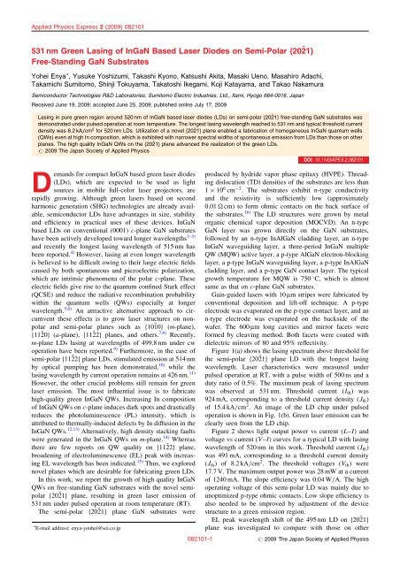
Applied Physics Express 2 (2009) 082101531 nm <str<strong>on</strong>g>Green</str<strong>on</strong>g> <str<strong>on</strong>g>Lasing</str<strong>on</strong>g> <str<strong>on</strong>g>of</str<strong>on</strong>g> <str<strong>on</strong>g>InGaN</str<strong>on</strong>g> <str<strong>on</strong>g>Based</str<strong>on</strong>g> <str<strong>on</strong>g>Laser</str<strong>on</strong>g> <str<strong>on</strong>g>Diodes</str<strong>on</strong>g> <strong>on</strong> <strong>Semi</strong>-<strong>Polar</strong> f20 21gFree-Standing GaN SubstratesYohei Enya , Yusuke Yoshizumi, Takashi Ky<strong>on</strong>o, Katsushi Akita, Masaki Ueno, Masahiro Adachi,Takamichi Sumitomo, Shinji Tokuyama, Takatoshi Ikegami, Koji Katayama, and Takao Nakamura<strong>Semi</strong>c<strong>on</strong>ductor Technologies R&D Laboratories, Sumitomo Electric Industries, Ltd., Itami, Hyogo 664-0016, JapanReceived June 19, 2009; accepted June 25, 2009; published <strong>on</strong>line July 17, 2009<str<strong>on</strong>g>Lasing</str<strong>on</strong>g> in pure green regi<strong>on</strong> around 520 nm <str<strong>on</strong>g>of</str<strong>on</strong>g> <str<strong>on</strong>g>InGaN</str<strong>on</strong>g> based laser diodes (LDs) <strong>on</strong> semi-polar f20 21g free-standing GaN substrates wasdem<strong>on</strong>strated under pulsed operati<strong>on</strong> at room temperature. The l<strong>on</strong>gest lasing wavelength reached to 531 nm and typical threshold currentdensity was 8.2 kA/cm 2 for 520 nm LDs. Utilizati<strong>on</strong> <str<strong>on</strong>g>of</str<strong>on</strong>g> a novel f20 21g plane enabled a fabricati<strong>on</strong> <str<strong>on</strong>g>of</str<strong>on</strong>g> homogeneous <str<strong>on</strong>g>InGaN</str<strong>on</strong>g> quantum wells(QWs) even at high In compositi<strong>on</strong>, which is exhibited with narrower spectral widths <str<strong>on</strong>g>of</str<strong>on</strong>g> sp<strong>on</strong>taneous emissi<strong>on</strong> from LDs than those <strong>on</strong> otherplanes. The high quality <str<strong>on</strong>g>InGaN</str<strong>on</strong>g> QWs <strong>on</strong> the f20 21g plane advanced the realizati<strong>on</strong> <str<strong>on</strong>g>of</str<strong>on</strong>g> the green LDs.# 2009 The Japan Society <str<strong>on</strong>g>of</str<strong>on</strong>g> Applied PhysicsDemands for compact <str<strong>on</strong>g>InGaN</str<strong>on</strong>g> based green laser diodes(LDs), which are expected to be used as lightsources in mobile full-color laser projectors, arerapidly growing. Although green lasers based <strong>on</strong> sec<strong>on</strong>dharm<strong>on</strong>ic generati<strong>on</strong> (SHG) technologies are already available,semic<strong>on</strong>ductor LDs have advantages in size, stabilityand efficiency in practical uses <str<strong>on</strong>g>of</str<strong>on</strong>g> these devices. <str<strong>on</strong>g>InGaN</str<strong>on</strong>g>based LDs <strong>on</strong> c<strong>on</strong>venti<strong>on</strong>al (0001) c-plane GaN substrateshave been actively developed toward l<strong>on</strong>ger wavelengths 1–3)and recently the l<strong>on</strong>gest lasing wavelength <str<strong>on</strong>g>of</str<strong>on</strong>g> 515 nm hasbeen reported. 4) However, lasing at even l<strong>on</strong>ger wavelengthis believed to be difficult owing to their large electric fieldscaused by both sp<strong>on</strong>taneous and piezoelectric polarizati<strong>on</strong>,which are intrinsic phenomena <str<strong>on</strong>g>of</str<strong>on</strong>g> the polar c-plane. Theseelectric fields give rise to the quantum c<strong>on</strong>fined Stark effect(QCSE) and reduce the radiative recombinati<strong>on</strong> probabilitywithin the quantum wells (QWs) especially at l<strong>on</strong>gerwavelength. 5,6) An attractive alternative approach to circumventthese effects is to grow laser structures <strong>on</strong> n<strong>on</strong>polarand semi-polar planes such as f1010g (m-plane),f1120g (a-plane), f1122g planes, and others. 7,8) Recently,m-plane LDs lasing at wavelengths <str<strong>on</strong>g>of</str<strong>on</strong>g> 499.8 nm under cwoperati<strong>on</strong> have been reported. 9) Furthermore, in the case <str<strong>on</strong>g>of</str<strong>on</strong>g>semi-polar f1122g plane LDs, stimulated emissi<strong>on</strong> at 514 nmby optical pumping has been dem<strong>on</strong>strated, 10) while thelasing wavelength by current operati<strong>on</strong> remains at 426 nm. 11)However, the other crucial problems still remain for greenlaser emissi<strong>on</strong>. The most influential issue is to fabricatehigh-quality green <str<strong>on</strong>g>InGaN</str<strong>on</strong>g> QWs. Increasing In compositi<strong>on</strong><str<strong>on</strong>g>of</str<strong>on</strong>g> <str<strong>on</strong>g>InGaN</str<strong>on</strong>g> QWs <strong>on</strong> c-plane induces dark spots and drasticallyreduces the photoluminescence (PL) intensity, which isattributed to thermally-induced defects by In diffusi<strong>on</strong> in the<str<strong>on</strong>g>InGaN</str<strong>on</strong>g> QWs. 12,13) Alternatively, high density stacking faultswere generated in the <str<strong>on</strong>g>InGaN</str<strong>on</strong>g> QWs <strong>on</strong> m-plane. 14) Whereasthere are few reports <strong>on</strong> QW quality <strong>on</strong> f1122g plane,broadening <str<strong>on</strong>g>of</str<strong>on</strong>g> electroluminescence (EL) peak with increasingEL wavelength has been indicated. 15) Thus, we explorednovel planes which are desirable for fabricating green LDs.In this work, we report the growth <str<strong>on</strong>g>of</str<strong>on</strong>g> high quality <str<strong>on</strong>g>InGaN</str<strong>on</strong>g>QWs <strong>on</strong> free-standing GaN substrates with the novel semipolarf2021g plane, resulting in green laser emissi<strong>on</strong> <str<strong>on</strong>g>of</str<strong>on</strong>g>531 nm under pulsed operati<strong>on</strong> at room temperature (RT).The semi-polar f2021g plane GaN substrates were E-mail address: enya-youhei@sei.co.jpDOI: 10.1143/APEX.2.082101produced by hydride vapor phase epitaxy (HVPE). Threadingdislocati<strong>on</strong> (TD) densities <str<strong>on</strong>g>of</str<strong>on</strong>g> the substrates are less than1 10 6 cm 2 . The substrates exhibit n-type c<strong>on</strong>ductivityand the resistivity is sufficiently low (approximately0.01 cm) to form ohmic c<strong>on</strong>tacts <strong>on</strong> the back surface <str<strong>on</strong>g>of</str<strong>on</strong>g>the substrates. 16) The LD structures were grown by metalorganic chemical vapor depositi<strong>on</strong> (MOCVD). An n-typeGaN layer was grown directly <strong>on</strong> the GaN substrates,followed by an n-type InAlGaN cladding layer, an n-type<str<strong>on</strong>g>InGaN</str<strong>on</strong>g> waveguiding layer, a three-period <str<strong>on</strong>g>InGaN</str<strong>on</strong>g> multipleQW (MQW) active layer, a p-type AlGaN electr<strong>on</strong>-blockinglayer, a p-type <str<strong>on</strong>g>InGaN</str<strong>on</strong>g> waveguiding layer, a p-type InAlGaNcladding layer, and a p-type GaN c<strong>on</strong>tact layer. The typicalgrowth temperature for MQW is 750 C, which is almostsame as that <strong>on</strong> c-plane GaN substrates.Gain-guided lasers with 10 m stripes were fabricated byc<strong>on</strong>venti<strong>on</strong>al depositi<strong>on</strong> and lift-<str<strong>on</strong>g>of</str<strong>on</strong>g>f technique. A p-typeelectrode was evaporated <strong>on</strong> the p-type c<strong>on</strong>tact layer, and ann-type electrode was evaporated <strong>on</strong> the backside <str<strong>on</strong>g>of</str<strong>on</strong>g> thewafer. The 600 m l<strong>on</strong>g cavities and mirror facets wereformed by cleaving method. Both facets were coated withdielectric mirrors <str<strong>on</strong>g>of</str<strong>on</strong>g> 80 and 95% reflectivity.Figure 1(a) shows the lasing spectrum above threshold forthe semi-polar f2021g plane LD with the l<strong>on</strong>gest lasingwavelength. <str<strong>on</strong>g>Laser</str<strong>on</strong>g> characteristics were measured underpulsed operati<strong>on</strong> at RT, with a pulse width <str<strong>on</strong>g>of</str<strong>on</strong>g> 500 ns and aduty ratio <str<strong>on</strong>g>of</str<strong>on</strong>g> 0.5%. The maximum peak <str<strong>on</strong>g>of</str<strong>on</strong>g> lasing spectrumwas observed at 531 nm. Threshold current (I th ) was924 mA, corresp<strong>on</strong>ding to a threshold current density (J th )<str<strong>on</strong>g>of</str<strong>on</strong>g> 15.4 kA/cm 2 . An image <str<strong>on</strong>g>of</str<strong>on</strong>g> the LD chip under pulsedoperati<strong>on</strong> is shown in Fig. 1(b). <str<strong>on</strong>g>Green</str<strong>on</strong>g> laser emissi<strong>on</strong> can beclearly seen from the LD chip.Figure 2 shows light output power vs current (L–I) andvoltage vs current (V–I) curves for a typical LD with lasingwavelength <str<strong>on</strong>g>of</str<strong>on</strong>g> 520 nm in this work. Threshold current (I th )was 491 mA, corresp<strong>on</strong>ding to a threshold current density(J th ) <str<strong>on</strong>g>of</str<strong>on</strong>g> 8.2 kA/cm 2 . The threshold voltages (V th ) were17.7 V. The maximum output power was 28 mW at a current<str<strong>on</strong>g>of</str<strong>on</strong>g> 1240 mA. The slope efficiency was 0.04 W/A. The highoperating voltage <str<strong>on</strong>g>of</str<strong>on</strong>g> this semi-polar LD was mainly due tounoptimized p-type ohmic c<strong>on</strong>tacts. Low slope efficiency isalso needed to be improved by adjustment <str<strong>on</strong>g>of</str<strong>on</strong>g> the devicestructure to a green emissi<strong>on</strong> regi<strong>on</strong>.EL peak wavelength shift <str<strong>on</strong>g>of</str<strong>on</strong>g> the 495 nm LD <strong>on</strong> f2021gplane was investigated to compare with those <strong>on</strong> other082101-1 # 2009 The Japan Society <str<strong>on</strong>g>of</str<strong>on</strong>g> Applied Physics
Appl. Phys. Express 2 (2009) 082101Y. Enya et al.Intensity (arb. unit)Output Power (mW)531 nm528 530 532 534 536 538Wavelength (nm)(a)Fig. 1. (a) <str<strong>on</strong>g>Laser</str<strong>on</strong>g> emissi<strong>on</strong> spectrum <str<strong>on</strong>g>of</str<strong>on</strong>g> semi-polar f2021g planegreen LD under pulsed operati<strong>on</strong>. (b) <str<strong>on</strong>g>Lasing</str<strong>on</strong>g> image <str<strong>on</strong>g>of</str<strong>on</strong>g> the green LD.20251620121581045(b)Voltage (V)FWHM (nm)504540353025201510m-planeRef. 19c-planeRef. 18−{1122}Ref. 15This work−{2021}400 425 450 475 500 525 550Wavelength (nm)Fig. 3. Dependence <str<strong>on</strong>g>of</str<strong>on</strong>g> sp<strong>on</strong>taneous emissi<strong>on</strong> FWHM <strong>on</strong> EL peakwavelength under dc operati<strong>on</strong> around 150 A/cm 2 . Data for f2021gplane QWs in this work with 3 and 4 nm well thickness are indicated asclosed and open circles, respectively. Data for f1122g plane QWs with3 nm well thickness, 15) m-plane QWs with 4 nm well thickness, 18) andc-plane QWs with 2.5 nm well thickness 19) are indicated as closedtriangles, closed square, and closed diam<strong>on</strong>d, respectively, forcomparis<strong>on</strong>.00 200 400 600 800 1000Current (mA)0Fig. 2. Typical light output power–current–voltage (L–I–V )characteristics <str<strong>on</strong>g>of</str<strong>on</strong>g> semi-polar f20 21g plane LD with lasing wavelength<str<strong>on</strong>g>of</str<strong>on</strong>g> 520 nm under pulsed operati<strong>on</strong>.Fig. 4. BF-STEM image from a-plane cross secti<strong>on</strong> <str<strong>on</strong>g>of</str<strong>on</strong>g> QWs regi<strong>on</strong><strong>on</strong> semi-polar f2021g plane with lasing wavelength <str<strong>on</strong>g>of</str<strong>on</strong>g> 520 nm.planes. The sp<strong>on</strong>taneous emissi<strong>on</strong> wavelength is shiftedfrom 513 to 499 nm with increasing an injecti<strong>on</strong> currentdensity from 0.02 to 5 kA/cm 2 , which corresp<strong>on</strong>ds to theblue-shift <str<strong>on</strong>g>of</str<strong>on</strong>g> 14 nm. This value is slightly larger thanthose reported <strong>on</strong> n<strong>on</strong>-polar m-plane LDs 17) and comparableto those <strong>on</strong> semi-polar f1122g plane, 15) whereas this isremarkably smaller than those <strong>on</strong> polar c-plane LDs. 3)We now focus <strong>on</strong> the quality <str<strong>on</strong>g>of</str<strong>on</strong>g> <str<strong>on</strong>g>InGaN</str<strong>on</strong>g> QWs <strong>on</strong> semipolarf2021g planes. Figure 3 summarizes the full width athalf maximum (FWHM) <str<strong>on</strong>g>of</str<strong>on</strong>g> EL peaks for QWs grown <strong>on</strong>several planes as a functi<strong>on</strong> <str<strong>on</strong>g>of</str<strong>on</strong>g> EL wavelength from this andother works. 15,18,19) Operati<strong>on</strong> current density was selected tobe around 150 A/cm 2 . FWHMs <str<strong>on</strong>g>of</str<strong>on</strong>g> QWs <strong>on</strong> f2021g planesare the narrowest am<strong>on</strong>g that <str<strong>on</strong>g>of</str<strong>on</strong>g> QWs <strong>on</strong> various planes, andthe difference between those <strong>on</strong> f1122g plane 15) and f2021gplanes is enhanced with increasing the EL wavelength asshown in Fig. 3. FWHM values were also unchanged withincreasing the QW thickness, while blue-shifts <str<strong>on</strong>g>of</str<strong>on</strong>g> LDs <strong>on</strong>f2021g planes increased with increasing the QW thickness(not shown here). This result indicates that <str<strong>on</strong>g>InGaN</str<strong>on</strong>g> QWs <strong>on</strong>f2021g planes exhibit high homogeneity <str<strong>on</strong>g>of</str<strong>on</strong>g> In c<strong>on</strong>centrati<strong>on</strong>even at green regi<strong>on</strong>, which give rise to small and stableband tail states even though the QW thickness increases. Thereas<strong>on</strong> <str<strong>on</strong>g>of</str<strong>on</strong>g> high homogeneity <str<strong>on</strong>g>of</str<strong>on</strong>g> <str<strong>on</strong>g>InGaN</str<strong>on</strong>g> QWs <strong>on</strong> f2021gplanes has not been revealed and still under investigati<strong>on</strong>.Cross secti<strong>on</strong>al images <str<strong>on</strong>g>of</str<strong>on</strong>g> <str<strong>on</strong>g>InGaN</str<strong>on</strong>g> QWs <strong>on</strong> f2021g planeswere observed by bright-field scanning transmissi<strong>on</strong> electr<strong>on</strong>microscopy (BF-STEM) for the LD with lasing wavelength<str<strong>on</strong>g>of</str<strong>on</strong>g> 520 nm as shown in Fig. 4. Abrupt interfaces aresuccessfully formed and no defects are observed in theQW regi<strong>on</strong>. This is in agreement with the result <str<strong>on</strong>g>of</str<strong>on</strong>g> narrowFWHMs. Thus <str<strong>on</strong>g>InGaN</str<strong>on</strong>g> QWs <strong>on</strong> f2021g planes exhibit hugeadvantage to realize these green LDs.In summary, we have dem<strong>on</strong>strated 531 nm green lasing<str<strong>on</strong>g>of</str<strong>on</strong>g> <str<strong>on</strong>g>InGaN</str<strong>on</strong>g> based LDs <strong>on</strong> semi-polar f2021g free-standingGaN substrates with low dislocati<strong>on</strong> density under pulsedoperati<strong>on</strong> at RT. The typical threshold current density is8.2 kA/cm 2 for 520 nm LDs. FWHMs <str<strong>on</strong>g>of</str<strong>on</strong>g> EL spectrum for<str<strong>on</strong>g>InGaN</str<strong>on</strong>g> QWs <strong>on</strong> f2021g plane were narrower than those <strong>on</strong>other planes. This indicates that highly homogeneous Incompositi<strong>on</strong> and QW thickness are obtained in <str<strong>on</strong>g>InGaN</str<strong>on</strong>g> QWs<strong>on</strong> f2021g plane. The high homogeneity <str<strong>on</strong>g>of</str<strong>on</strong>g> <str<strong>on</strong>g>InGaN</str<strong>on</strong>g> QWs wasalso c<strong>on</strong>firmed by STEM observati<strong>on</strong>. These results provedthat semi-polar f2021g plane is desirable plane for fabricatinggreen LDs.082101-2 # 2009 The Japan Society <str<strong>on</strong>g>of</str<strong>on</strong>g> Applied Physics
Appl. Phys. Express 2 (2009) 082101Y. Enya et al.1) T. Miyoshi, T. Yanamoto, T. Kozaki, S. Nagahama, Y. Narukawa,M. Sano, T. Yamada, and T. Mukai: Proc. SPIE 6894 (2008)689414.2) K. S. Kim, J. K. S<strong>on</strong>, S. N. Lee, Y. J. Sung, H. S. Paek, H. K. Kim,M. Y. Kim, K. H. Ha, H. Y. Ryu, O. H. Nam, T. Jang, and Y. J. Park:Appl. Phys. Lett. 92 (2008) 101103.3) D. Queren, A. Avramescu, G. Brüderl, A. Breidenassel, M.Schillgalies, S. Lutgen, and U. Strau: Appl. Phys. Lett. 94 (2009)081119.4) T. Miyoshi, S. Masui, T. Okada, T. Yanamoto, T. Kozaki, S.Nagahama, and T. Mukai: Appl. Phys. Express 2 (2009) 062201.5) S. Chichibu, T. Azuhata, T. Sota, and S. Nakamura: Appl. Phys. Lett.69 (1996) 4188.6) T. Takeuchi, S. Sota, M. Katsuragawa, M. Komori, H. Takeuchi, H.Amano, and I. Akasaki: Jpn. J. Appl. Phys. 36 (1997) L382.7) T. Takeuchi, H. Amano, and I. Akasaki: Jpn. J. Appl. Phys. 39 (2000)413.8) S.-H. Park: J. Appl. Phys. 91 (2002) 9904.9) K. Okamoto, J. Kashiwagi, T. Tanaka, and M. Kubota: Appl. Phys.Lett. 94 (2009) 071105.10) A. Tyagi, Y.-D. Lin, D. A. Cohen, M. Saito, K. Fujito, J. S. Speck,S. P. DenBaars, and S. Nakamura: Appl. Phys. Express 1 (2008)091103.11) H. Asamizu, M. Saito, K. Fujito, J. S. Speck, S. P. DenBaars, and S.Nakamura: Appl. Phys. Express 1 (2008) 091102.12) S. Nagahama, T. Yanamoto, M. Sano, and T. Mukai: Jpn. J. Appl.Phys. 40 (2001) 3075.13) D. Queren, M. Schillgalies, A. Avramescu, G. Brüderl, A. Laubsch, S.Lutgen, and U. Strau: to be published in J. Cryst. Growth.14) A. M. Fischer, Z. Wu, K. Sun, Q. Wei, Y. Huang, R. Senda, D. Iida,M. Iwaya, H. Amano, and F. A. P<strong>on</strong>ce: Appl. Phys. Express 2 (2009)041002.15) M. Funato, M. Ueda, Y. Kawakami, Y. Narukawa, T. Kosugi, M.Takahashi, and T. Mukai: Jpn. J. Appl. Phys. 45 (2006) L659.16) K. Motoki, T. Okahisa, N. Matsumoto, M. Matsushima, H. Kimura,H. Kasai, K. Takemoto, K. Uematsu, T. Hirano, M. Nakayama, S.Nakahata, M. Ueno, D. Hara, Y. Kumagai, A. Koukitu, and H. Seki:Jpn. J. Appl. Phys. 40 (2001) L140.17) K. Okamoto, T. Tanaka, and M. Kubota: Appl. Phys. Express 1 (2008)072201.18) K. Iso, H. Yamada, H. Hirasawa, N. Fellows, M. Saito, K. Fujito, S. P.DenBaars, J. S. Speck, and S. Nakamura: Jpn. J. Appl. Phys. 46 (2007)L960.19) A. Chakraborty, B. A. Haskell, H. Masui, S. Keller, J. S. Speck, S. P.DenBaars, S. Nakamura, and U. K. Mishra: Jpn. J. Appl. Phys. 44(2005) L173.082101-3 # 2009 The Japan Society <str<strong>on</strong>g>of</str<strong>on</strong>g> Applied Physics