
You also want an ePaper? Increase the reach of your titles
YUMPU automatically turns print PDFs into web optimized ePapers that Google loves.
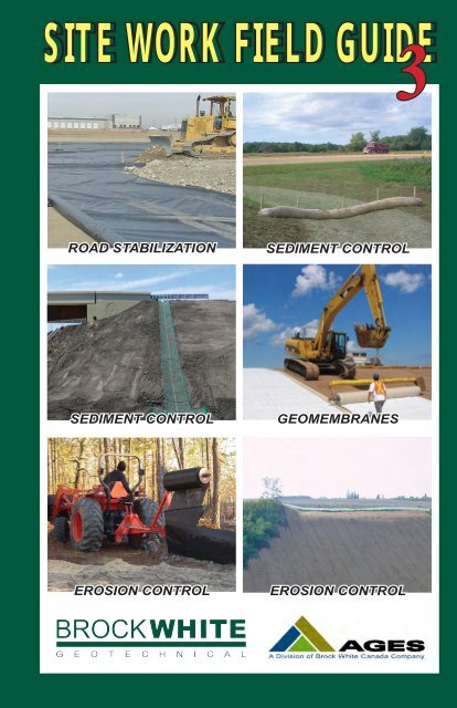
<strong>SITE</strong> <strong>WORK</strong> <strong>FIELD</strong> <strong>GUIDE</strong>3ROAD STABILIZATIONROAD STABILIZATIONSEDIMENT CONTROLGEOMEMBRANESSEDIMENT CONTROLSEDIMENT CONTROLGEOMEMBRANESEROSION CONTROLEROSION CONTROLEROSION CONTROL
Silt and Sediment Control Guidelines:Field Guide for the Resource IndustryGuidelinesSite Work Field GuideThe following field guide outlines the general guideline for placement oferosion and sediment control materials and details the various types of siltcontrol materials suitable for applications typical of resource industryconstruction. Attached are corresponding drawings, referenced in the text,that relate to these descriptions.The following typical applications are addressed here:1.) Road ditches2.) Bridge abutments and approaches3.) Fill sections4.) Natural drainage/culvert outlets5.) Sedimentation PondsMaterial types and specifications:1.) Standard AGES Premium Silt Fencing2.) Wire Supported Silt Fencing3.) Sediment Logs4.) Erosion Control Matting5.) ScourStop6.) FlocculantsTYPICAL APPLICATIONS1.) Road DitchesWhen downhill grades are sufficient to create flowing water in ditches,measures should be taken to reduce flow velocities and minimize erosion.Wherever possible divert the ditches with the use of cross swales to directflow into natural vegetation, treed areas, or other protected areas. Before thesediversions, sediment logs should be used to trap any silt, in order to avoiddepositing eroded materials into natural areas and slow flow to prevent erosion(see Figure 3). Where a defined ditch is not present a series of silt fence canbe used to keep smaller amounts of flowing water in check (see Figure 1 andFigure 4).2.) Bridge Approaches and AbutmentsTypically it is required to build up the grade at bridge locations. In theseinstances it will be required to take extra precaution as the work progressesand once work is completed, due to the immediate proximity to the creeks andthe potential of siltation to streams.www.<strong>Brock</strong><strong>White</strong>.com A - 1
GuidelinesSite Work Field Guide2.) Bridge Approaches and Abutments ContinuedSmall creeks have a tendency to freeze down and spread wide during thewinter, causing a wider flood area in the spring. Proximity to the creek canalso be a concern when large rainfall events cause creeks to wander or floodagainst the new road fill at the bridge approaches. Larger fills or those subjectto scour from spring runoff should be armored with rock or erosion mattingon the upstream side to minimize erosion from rainfall on the slopes and fromwater flowing off the road grade (see Figure 1: Erosion/Sediment Control,Detail G). The downstream side of the embankment can be isolated with siltfences at the toe of the embankment (see Figure 1: Erosion/Sediment Control,Detail H).Smaller fills can be left uncovered, but a silt fence should be placed along thetoe of the fill to hold eroded particles close to the toe and away fromdrainages. If a ditch is also present along the toe of the embankment(i.e. running parallel to the embankment), sediment logs should also beplaced to slow flow and trap sediment (see Figure 1: Erosion/SedimentControl, Detail E).Additional wing walls may be required to hold the fill in place at the bridgesupport areas. Gabion baskets can be used to restrain and protect the fill inhigh water situations. This may also be accomplished with timbers or logs andwill need to be assessed during the construction of the bridges (see Figure 1:Erosion/Sediment Control, Detail F).3.) Fill Sections (Lease pads, road embankments and stockpiles)Fill sections are subject to erosion from rainfall and snowmelt. Anyexposed slope that has the ability to shed water towards a natural drainage orwaterway should be protected by an erosion blanket. For temporarystockpiles silt fence can be installed at the toe to collect material washed fromthe exposed fill. A tackifier, such as Silt Stop, can also be used to temporarilystabilize the slope to prevent erosion on areas that will be left undisturbed.4.) Culvert discharges, ditch ends and log crossingsDischarge areas can be dealt with by applying sections of silt fence within theright-of-way to retain silts before they discharge into the natural drainages.Silt fences can be installed in wide semi-circle configurations to allow a wideintercept zone where there is often little to no defined watercourse. A row ofsilt fence or sediment logs can be placed immediately downstream of the logcrossing to trap particles washing from the fill or from the road.A - 2BURNABY • LANGLEY • PRINCE GEORGE • EDMONTON • CALGARY • LLOYDMINSTER • SASKATOON • REGINA • WINNIPEG • THUNDER BAY
GuidelinesSite Work Field Guide4.) Culvert discharges, ditch ends and log crossings continuedThe immediate area of a culvert discharge should be protected by rip rap or analternative such as ScourStop to reduce velocity and prevent scour. Logcrossings should be built with a layer of non-woven geotextile over the logsprior to placing fill. This keeps the fill material from bleeding into voids, andwill reduce the amount of fines entering the drainage area.5.) Sedimentation pondsSedimentation ponds may be implemented on occasions where the naturallay of the land and drainage lend favorably to this. A pond can be created byexcavating a small depression (about 1m) at the end of a long ditch section.The outlet elevation is to be kept higher, and approximately the top 300 mmdammed with sediment logs or rock. The pond will fill with water and spillover the sediment log or rock to drain away into a selected area, leavingsediment in the pond (see Figure 1: Erosion/Sediment Control, Detail I). FlocLogs can also be integrated into a pond system to decrease the settling time ofthe sediment.SEDIMENT CONTROL MATERIALS1.) AGES Premium Silt Fencing (see Figure 2: Supported Silt Fence,Detail J) This is a conventional woven silt fence that has been improved tomeet Canadian climatic and construction requirements. It has been designedto be tough and long lasting, and be able to withstand wind and general roughhandling (due to rough installation or fill piling against it, etc.).AGES has designed this silt fence with four longitudinal reinforcing stripsthat are twice the strength of a regular silt fence weave. It has a higher thanaverage flow capacity, and is supplied pre-attached to 2” x 2” wooden posts at10’ spacing. Standard roll size is 3’ x 100’. The fabric is made in Calgary andis available in green (to blend with the natural environment) as well as orangeand standard black.2.) Wire Supported Silt Fencing (see Figure 2: Supported Silt Fence,Detail K) AGES wire supported silt fencing is composed of the same AGESPremium silt fence as above and is pre-attached to steel page wire fence. Thisproduct is provided in 3’ x 110’ rolls without stakes. The fence is usuallyattached in the field to steel “T”- Posts or heavy-duty fence posts for morelong-term installations. The steel page wire provides full support of the fabricto keep from sagging, and to support where fill may roll onto fence.www.<strong>Brock</strong><strong>White</strong>.com A - 3
GuidelinesSite Work Field Guide3.) Sediment Logs (see Figure 4: Ditch Sediment Control)Sediment Logs are comprised of excelsior fibers that reduce velocity allowingsediment to drop out of suspension while allowing water to filter through theporous fibers. They are well-suited for ditches, slope interruption and perimetersediment devices.4.) Erosion Control MattingRECBs (Rolled Erosion Control Blankets) are biodegradable and syntheticblankets used to cover exposed soil in ditches and fill slopes. They work toprotect the soil and seed from rainfall, wind, heat and overland flow therebyencouraging germination and reducing competition species. The matting ispinned to a prepared area that has been seeded.5.) ScourStopScourStop is a rip rap alternative for culvert discharge areas to provide atransition zone for concentrated flows of water. It protects the immediate areafrom erosion and redirects the flow to effectively reduce velocity downstreamof the discharge area. It is an HDPE mat with voids present to allow for vegetationto be established as a green alternative to rip rap.6.) Silt Stop & Floc LogsThese are two forms of flocculant that work with the soils present to bind soilparticles together. SiltStop is a powder that is broadcast over exposed soil andworks as a tackifier. Floc Logs are in a block form that, when placed withinflowing water, increase the settling capabilities of sediment that is suspended.Other erosion and sediment control materials are available from<strong>Brock</strong> <strong>White</strong>, though these materials will address most of the issuesyou encounter on a day-to-day basis.Please call 403-204-3322 or 1-877-304-2437 for design assistance,assistance developing an erosion control plan, or help with any othererosion or sediment control issue.A - 4BURNABY • LANGLEY • PRINCE GEORGE • EDMONTON • CALGARY • LLOYDMINSTER • SASKATOON • REGINA • WINNIPEG • THUNDER BAY
GuidelinesSite Work Field GuideApplications of Erosion and Sediment Control PracticesThe common reason erosion and sediment control practices are ineffectiveis not lack of common sense. Frequently, the wrong BMP is implementedfor the type of control needed. A sediment control BMP should not beused for erosion control and an erosion control BMP should not be usedwhen runoff control is needed. When the needed control is treated with thewrong type of BMP, failure usually occurs.For example, a silt fence is placed across a slope to prevent erosion.Maybe the designer wanted to stop sheet and rill erosion. In actual practicethe silt fence collected and concentrated water which was diverted to a lowspot where the fence becomes overloaded and failed. An Erosion ControlBMP should have been chosen to treat the erosion problem. Silt fences areintended for sediment control and should, therefore, be installed in relativelyflat areas suitable for ponding water and depositing sediment.A good way to avoid confusion when choosing BMPs is to have a clearunderstanding of what type control is needed and what are the correspondingBMPs. There are three general categories of controls that have distincttreatments associated with them; 1) erosion control, 2) runoff control, and3) sediment control.Erosion ControlErosion control is any practice that protects the soil surfaces and preventsthe soil particles from being detached by rainfall or wind. Erosion control,therefore, is a source control that treats the soil as a resource that has valueand should be kept in place.www.<strong>Brock</strong><strong>White</strong>.com A - 5
GuidelinesSite Work Field GuideSediment ControlSedimentation is the deposition of soil particles that have been transportedby water or wind. The amount of sediment produced during constructionis directly proportional to the degree and effectiveness of erosion controlpractices implemented. The quantity and size of the particles transportedincreases with the velocity of the runoff.Sediment control is used to keep sediment, the product of erosion, on-site.Sediment control involves the construction of structures that allowsediment to settle out of suspension. Sediment control structures, therefore,require frequent inspection and maintenance.Generally, sediment is retained on-site by two methods: a) slowing runoffvelocities, as they flow through an area, sufficiently so that sedimentcannot be transported, and b) impounding sediment-laden runoff for aperiod of time so that the soil particles settle out.Sediment controls are not filters. Practices referred to as “sedimentfiltering” actually work by slowing velocities and allowing sedimentimpoundment to de-water in a very slow and controlled manner. Foreffective sediment control planning and design, materials such asgeotextiles, silt fences, and straw bales should be considered for theirability to impound water and slow runoff velocities, not for their ability to“filter” sediment.Key Point: Effective sediment control involves ponding sediment-ladenrunoff long enough for the soil particles to settle out of suspension.Reducing runoff velocities will also reduce sediment transport and therebyhelp retain sediment on-site.What are some effective sediment control BMPs?Key point: Structural sediment control can be divided into three generaltypes; 1) sediment basins, 2) sediment traps, and 3) sediment barriers.Temporary Sediment Basins are recommended for the outlet of disturbeddrainage areas ranging from 5 ac (2 ha) to 100 ac (40 ha). Sediment Basinsshould be designed by a qualified professional.www.<strong>Brock</strong><strong>White</strong>.com A - 7
GuidelinesSite Work Field GuideWhat are some effective sediment control BMPs? continued...Temporary Sediment Traps are recommended for disturbed drainage areasless than 5 ac (2 ha). A typical Sediment Trap designed to handle .5 inches(12.7 mm) of runoff over a 24 hour period would require a settling zonecapacity of 67 yd3 / ac (130 m3 / ha) of contributing drainage area and asediment storage capacity of 33 yd3 / ac (65 m3 / ha) of drainage area.Excavated Sediment Traps require less rigorous design work, are smallerin size and they are easier to construct, therefore, a preferable alternativeis to sub-divide large projects into smaller sub-areas (less than 5 ac) andutilize numerous sediment traps. Multiple traps and / or additional volumemay be required to accommodate site specific rainfall and soil conditions.This approach may facilitate phased construction along relatively narrowhighway ROW.Excavated Storm Drain Inlets are small excavated sediment traps locatedat storm drain inlets and are effective as part of phased construction. Thedesign capacity of excavated inlet sediment traps shall be 67 yd3 / acre(1800 ft3 / ac) of contributing drainage area. These excavations aretemporary and they are not very effective for trapping small particles (siltand clay) and they should not be used where runoff velocities are high.Sediment Barriers are BMPs that are intended to separate sediment fromsheet flow runoff. They function by reducing runoff velocity and pondingsmall quantities of storm water. Sediment barriers are only intended forareas experiencing sheet flow and they must be installed in areas that canpond water and accumulate sediment and, most importantly, they must beaccessible for cleanout. Sediment barriers are the most common type ofpractices used on construction sites.• Sediment Barriers• Silt Fence• Straw Wattle or Sediment Log• Continuous Berms• Storm Drain Inlet BarriersA - 8BURNABY • LANGLEY • PRINCE GEORGE • EDMONTON • CALGARY • LLOYDMINSTER • SASKATOON • REGINA • WINNIPEG • THUNDER BAY
GuidelinesSite Work Field GuideVegetation as a SolutionDense, healthy vegetation and the associated leaf litter protects the soilfrom raindrop impact. Raindrop impact is a major force in dislodging soilparticles which then allows them to move downslope or form a crust onthe soil surface. When a crust forms on the soil surface the rainfallinfiltration rate decreases and runoff increases.Vegetation also protects the soil from sheet and rill erosion. It shields thesoil surface from the transport of soil particles and scour from overlandflow (sheet flow) and it decreases the erosive energy of the flowing waterby reducing velocity.The shielding effect of the plant canopy and leaves is augmented by rootsand rhyzomes that hold the soil in place, improve the soil’s physical condition,and increase the rate of infiltration, further decreasing runoff. Plantsalso remove water from the soil through transpiration, thus increasing itscapacity to absorb water.Suitable vegetative cover provides excellent erosion protection, andreduces the need for high cost, low efficiency, high maintenance sedimentcontrol measures. Vegetative cover is relatively inexpensive to achieve andtends to be self-healing; it is often the only practical, long-term solution ofstabilization and erosion control on most disturbed sites.Initial investigation of site characteristics and planning for vegetationstabilization reduces its cost, minimizes maintenance and repair, andmakes other erosion and sediment control measures more effective andless costly to maintain. Permanent erosion control (post-constructionlandscaping) is also less costly where soils have not been eroded.Exposed subsoils are generally difficult to amend, are infertile, and requiremore irrigation. Natural, undisturbed areas can provide low-maintenancelandscaping, shade, and privacy. Large trees increase property values whenthey are properly protected during construction.A - 10BURNABY • LANGLEY • PRINCE GEORGE • EDMONTON • CALGARY • LLOYDMINSTER • SASKATOON • REGINA • WINNIPEG • THUNDER BAY
Vegetation as a Solution Continued...GuidelinesSite Work Field GuideBesides preventing erosion, healthy vegetative cover provides a stable landsurface, reduces heat reflectance and dust, restricts weed growth, andcomplements architecture. The result is a pleasant environment foremployees, tenants and customers, and an attractive site for homes.Property values can be increased dramatically by small investments inerosion control. The final landscaping represents a small fraction of totalconstruction costs, but can contribute greatly to an increased market valueof the development. Healthy vegetation and planned development willreduce concentrated flows and peak discharge, thus reducing channelerosion and flooding. Good, healthy vegetative cover greatly reduces theenvironmental impacts that poor water quality and habitat reduction ishaving on rivers and streams.Erosion Control Blankets and MatsDefinition: The installation of protective mulch blankets or soilstabilization mats (turf reinforcement mats) to the prepared soil surface ofa steep slope, channel or shoreline.Purpose: Erosion control blankets are used to temporarily stabilize andprotect disturbed soil from raindrop impact and surface erosion, to increaseinfiltration, decrease compaction and soil crusting, and to conserve soilmoisture. Mulching with erosion control blankets will increase thegermination rates for grasses and legumes and promote vegetationestablishment. Erosion control blankets also protect seeds from predators,reduce desiccation and evaporation by insulating the soil and seedenvironment.Some types of erosion control blankets and turf reinforcement mats arespecifically designed to stabilize channelized flow areas. These blanketsand mats can aide the establishment of vegetation in waterways andincrease the maximum permissible velocity of the given channel byreinforcing the soil and vegetation to resist the forces of erosion duringrunoff events. Stems, roots and rhizomes of the vegetation becomeintertwined with the mat, reinforcing the vegetation and anchoring the mat.www.<strong>Brock</strong><strong>White</strong>.com A - 11
GuidelinesSite Work Field GuideErosion Control Blankets and Mats Continued...Conditions Where Practice Applies: Establishing vegetation in channelsor on slopes may require additional measures beyond seeding and strawmulching. Conditions where erosion control blankets and mats areappropriate may include:• Slopes and disturbed soils where mulch must be anchored and othermethods such as crimping or tackifying are notfeasible nor adequate.• Steep slopes, generally steeper than 3:1• Slopes where erosion hazard is high.• Critical slopes adjacent to sensitive areas such as streams and wetlands.• Disturbed soil areas where planting is likely to be slow in providingadequate protective cover.• Channels with flow exceeding 2-4 ft./sec. (0.6-1 m/sec.).• In channels intended to be vegetated and where the design flowexceeds the permissible velocity. Allowable velocity, with turfreinforcement mats after vegetative establishment, is up to 10 ft/sec.(3 m/sec).Specifications: Erosion control blankets are generally a machine producedmat of organic, biodegradable mulch such as straw, curled wood fiber(excelsior), coconut fiber or a combination thereof, evenly distributed onor between photodegradable polypropylene or biodegradable natural fibernetting. Synthetic erosion control blankets are a machine produced mat ofultraviolet stabilized synthetic fibers and filaments. The nettings and mulchmaterial are stitched to ensure integrity and the blankets are provided inrolls for ease of handling and installation.Soil stabilization and turf reinforcement mats are high strength, flexible,machine produced, three dimensional matrix of nylon, polyethylene,polypropylene or polyvinyl chloride that have ultra violet (UV)stabilizers added to the compounds to ensure endurance and provide‘permanent vegetation stabilization.’A - 12BURNABY • LANGLEY • PRINCE GEORGE • EDMONTON • CALGARY • LLOYDMINSTER • SASKATOON • REGINA • WINNIPEG • THUNDER BAY
GuidelinesSite Work Field GuideErosion Control Blankets and Mats Continued...Planning Considerations: Erosion control blankets and turfreinforcement matting can be applied to problem areas to supplementnature’s erosion control system (vegetation) in its initial establishment andin providing a safe and ‘natural’ conveyance for high velocity stormwaterrunoff.These products are being used today in many applications wherepreviously a structural lining or armoring would have been required.Care must be taken to choose the type of blanket or matting which is moreappropriate for the specific needs of a project.There are many soil stabilization products available today and it is verydifficult to cover all the advantages, disadvantages and specifications ofall the manufactured blankets and mats. therefore, as with many erosioncontrol type products, there is no substitute for a thorough understandingof manufacture’s instructions and recommendations and a site visit by adesigner or plan reviewer to verify a product’s appropriateness.Site Preparation:Construction Specifications• Construction phasing minimizes risk.• Proper site preparation is essential to ensure complete contact of theprotection matting with the soil.• Grade and shape area of installation.• Remove all rocks, clods, vegetative or other obstructions so that theinstalled blankets or mats will have direct contact with the soil.• Prepare seedbed by loosening 2-3 inches (50-75 mm) of topsoil abovefinal grade.• Incorporate amendments, such as lime and fertilizer, into soil accordingto soil test and the seeding plan.www.<strong>Brock</strong><strong>White</strong>.com A - 13
Construction Specifications Continued...Installation in channels:GuidelinesSite Work Field Guide• Dig initial anchor trench 12 inches (0.3 m) deep and 6 inches (0.2 m)wide across the channel at the lower end of the project area.• Excavate intermittent check slots, 6 inches (0.2 m) deep and 6 inches(0.2 m) wide across the channel at 25-30 foot (7.6-9.1 m) intervalsalong the channel.• Cut longitudinal channel anchor slots 4 inches (101 mm) deep and 4inches (101 mm) wide along each side of the installation to bury edgesof matting. Whenever possible extend matting 2-3 inches (51-76 mm)above the crest of channel side slopes.• Beginning at the downstream end and in the center of the channel,place the initial end of the first roll in the anchor trench and securewith fastening devices at 1 foot (0.3 m) intervals.• Note: matting will initially be upside down in anchor trench.• In the same manner, position adjacent rolls in anchor trench,overlapping the preceding roll a minimum of 3 inches (76 mm).• Secure these initial ends of mats with anchors at 1 foot (300 mm)intervals, backfill and compact soil.• Unroll center strip of matting upstream. Stop at next check slot orterminal anchor trench.• Unroll adjacent mats upstream in similar fashion, maintaining a 3 inch(76 mm) overlap.• Fold and secure all rolls of matting snugly into all transverse checkslots. Lay mat in the bottom of the slot then fold back against itself.Anchor through both layers of mat at 1 inch (25 mm) intervals, thenbackfill and compact soil. Continue rolling all mat widths upstream tothe next check slot or terminal anchor trench.• Alternate method for noncritical installations: place two rows ofanchors on 6 inch (0.2 m) centers at 25-30 feet (7.6-9.1 m) intervals inlieu of excavated check slots.• Shingle-lap spliced ends by a minimum of 1 foot (0.3 m) with upstreammat on top to prevent uplifting by water or begin new rolls in a checkslot. Anchor overlapped area by placing two rows of anchors, 1 foot(0.3 m) apart on 1 foot (0.3 m) intervals.www.<strong>Brock</strong><strong>White</strong>.com A - 15
GuidelinesSite Work Field GuideConstruction Specifications Continued...Installation in channels continued...• Place edges of outside mats in previously excavated longitudinal slots,anchor using prescribed staple pattern, backfill and compact soil.• Anchor, fill and compact upstream end of mat in a 12 inch (0.3 m) x 6inch (0.2 m) terminal trench.• Secure mat to ground surface using U-shaped wire staples geotextilepins or wooden stakes.• Seed and fill turf reinforcement matting with soil, if specified.Soil filling if specified for turf reinforcement:• After seeding, spread and lightly rake 1/2-3/4 inches (13-19 mm) offine topsoil into the mat apertures to completely fill mat thickness. Usebackside of rake or other flat implement.• Spread topsoil using lightweight loader, backhoe, or other powerequipment. Avoid sharp turns with equipment. Do not drive tracked orheavy equipment over mat.• Avoid any traffic over matting if loose or wet soil conditions exist.• Use shovels, rakes or brooms for fine grading and touch up.• Smooth out soil filling, just exposing top netting of matrix.Inspection and Maintenance:• All blanket and mats should be inspected periodically followinginstallation.• Inspect installation after significant rainstorms to check for erosion andundermining. Any failure should be repaired immediately.• If washout or breakage occurs, re-install the material after repairing thedamage to the slope or drainageway.A - 16BURNABY • LANGLEY • PRINCE GEORGE • EDMONTON • CALGARY • LLOYDMINSTER • SASKATOON • REGINA • WINNIPEG • THUNDER BAY
Propex GeotexSite Work Field GuideFeaturing high tensile strengths which range from 135 to 370lbs and low elongations, ourGeotex woven geotextiles have a remarkable capacity for filtering soils, distributing loads,reducing rutting and extending the life of paved and unpaved roadways. Made fromindividual yarns woven together to provide dimensionally stable geotextiles, they areresistant to ultraviolet(UV) degradation and to biological and chemical environmentsnormally found in soils.www.<strong>Brock</strong><strong>White</strong>.com B - 1
Propex GeotexSite Work Field GuideGeotex soil reinforcement geotextiles are specially designed for structural reinforcement incivil and environmental applications. They are woven with high-tenacity polysester and/orpolypropylene yarns, and they possess superior hydraulic and strength characteristics.These properties make Geotex geotextiles ideal for reinforcing embankments over soft soils,steepened slopes, retaining walls, lagoon closures and landfill lining systems.Slopes reinforced with Geotex geotextilesmaximize land use in transportation and sitedevelopment projects.The unique weave of Geotex wovengeotextiles forms a robust fabric with hightensile strengths and superior hydrauliccharacteristics.Sudden changes in elevation may requirewrapped-face or modular block walls.Geotex soil reinforcement geotextileshelp protect new landfill lining systems in“piggyback” construction techniques.B - 2 BURNABY • LANGLEY • PRINCE GEORGE • EDMONTON • CALGARY • LLOYDMINSTER • SASKATOON • REGINA • WINNIPEG • THUNDER BAY
Propex GeotexSite Work Field GuideMade from the highest quality polypropylene fibers, our Geotex nonwoven geotextiles areneedlepunched to form a strong fabric that retains its dimensional stability, adding years tothe life of any roadway, railroad, landfill or civil/environmental engineering project. Used insubsurface drainage, separation, stabilization, erosion control and cushioning applications,our geotextiles are resistant to ultraviolet (UV) degradation and to bilogical and chemicalenvironments normally found in soils.www.<strong>Brock</strong><strong>White</strong>.com B - 3
Woven & Nonwoven Cross ReferenceSite Work Field GuideB - 4 BURNABY • LANGLEY • PRINCE GEORGE • EDMONTON • CALGARY • LLOYDMINSTER • SASKATOON • REGINA • WINNIPEG • THUNDER BAY
<strong>Brock</strong> <strong>White</strong> Biaxial Geogrid Comparison ChartSite Work Field Guidewww.<strong>Brock</strong><strong>White</strong>.com B - 5
Huesker Grid-ReinforcementSite Work Field GuideHaTelit® is made from high-modulus polyester and coated with bitumen to achievea good bond to the asphalt. One side has an ultra-lightweight nonwoven attached,also coated with bitumen. This nonwoven simplifies installation and ensurescontinuous bond between the layers.This strong bond allows HaTelit® to take up tensile forces and distribute themevenly over a large area. Therefore HaTelit® provides an effective method ofpreventing reflective cracking in asphalt layers. Over 35 years of experience withHaTelit® have shown that maintenance intervals can be increased by a factorof 3-4. This advantage applies in cold, temperate and hot climate zones. A roadreinforced with suitably designed and properly installed HaTelit® reinforcement willremain crack-free for many years.Properties:• High temperature stability• Elongation characteristics match the modulus of the asphalt• Long-term dynamic load-carrying capability• Good bonding characteristics with asphaltTypical applications:• Anti-cracking reinforcement in asphalt• Reinforcement of joints• Overlays to old concrete roads• Reinforcement of asphalt layers in hydraulic engineering and landfillHUESKER Synthetic GmbH isISO 9001:2000 accredited.HaTelit® is a registered trademarkof HUESKER Synthetic GmbH.B - 6 BURNABY • LANGLEY • PRINCE GEORGE • EDMONTON • CALGARY • LLOYDMINSTER • SASKATOON • REGINA • WINNIPEG • THUNDER BAY
Terrafix Biaxial GeogridsSite Work Field GuideBiaxial Geogrids forSuperior Reinforcementterrafix® Biaxial Geogrids provide a simple, cost effective solution for soilreinforcement. Improve roadways, highways and other heavily trafficked areaswith terrafix® Biaxial Geogrids.Even when conditions are less than perfect, including: weak subgrades,contaminated soils, heavy loads, high granular costs and shallow-buried utilities,an engineered solution is possible.Geogrids save time and money by:- reducing aggregate fill thicknesses- reducing sub-excavation- simplifying construction- extending service life of pavement- reducing labour and equipmentrequirementsImproved Performance for- Municipal roads- Highways- Railway ballast- Site access roads- Haul roads- Parking lots- Industrial shipping yards- Foundation footings… and moreAggregate interlocks with geogrid apertureswww.<strong>Brock</strong><strong>White</strong>.com B - 7
NAUE - Secugrid & CombigridSite Work Field GuideSecugrid and Combigrid geogrids are the next generation of geogrids produced with state ofthe art manufacturing technology unlike any other geogrid on the marketiplace today. Thereinforcement element is a highly oriented polypropylene or polyester strap that is extrudedand drawn to achieve high modulus and strength at low elongations. This is combined withNAUE patented vibratory welding technology to provide a structurally sound and stablegeogrid.Secugrid Q1 GeogridsThese biaxial geogrdis have uniform, square-shaped grid openings. With these geogrids themachine and cross direction extruded polypropylene straps exhibit uniform strengths in eachdirection. The numbers in each of the product names e.g. 30/30 for Secugrid 30/30 Q1 definemachine and cross machine direction ultimate strength values.Combigrid Q1 CompositeThe Combigrid series incorporate a needle-punched polypropylene or polyester Secutexnonwoven geotextile separator that is placed firmly between the flat straps on themanufacturing line during the production process.Stress Strain BehaviorSecugrid and Combigrid haveexcellent stress strain behaviorespecially in the low elongationrange which is important in basereinforcement applications.ApplicationsSecurgrid and Combigrid biaxialgeogrids are used in all basereinforcement applications.Secugrid and Combigridgeogrids can be used toincrease the bearingcapacity of soils, allow a highertraffic load on the base course,reduce rutting in a base courseand save costs by increasingdesign life-time, or reduce thebase course thickness.Typical applications are in roadbase reinforcement, parking lotstabilization and storage aresupport.B - 8 BURNABY • LANGLEY • PRINCE GEORGE • EDMONTON • CALGARY • LLOYDMINSTER • SASKATOON • REGINA • WINNIPEG • THUNDER BAY
Mud Mats(Patent Pending)AGES Mud MatsSite Work Field GuideCROSSINGSENSITIVE AREASALTERNATIVE TOROCK ENTRANCESRESIDENTIAL CONSTRUCTIONENTRANCE<strong>SITE</strong> ACCESSUnroll this amazing new product and drive on any muddy, swampy ground without gettingstuck, rutting or tracking mud off site.Mud Mats consist of pocketed, double-wall, high-strength fabric with high tensile reinforcingribs confined within each sleeve; this allows for easy deployment and amazing structuralstability. The mats connect together to form custom sizes. Ground pressure from vehicletires is reduced up to 40x causing minimal ground disturbance!•Light weight •Quick to deploy •Roll up when done •Washes easilyUse confidently in oil & gas construction, agriculture, golf & parks and other delicate areaswhere vehicle access is required.Each Mud Mat is 15’ x 8’ and approximately 90lbs. Custom sizes can be made byconnecting the straps of the Mud Mats together.www.<strong>Brock</strong><strong>White</strong>.com B - 9
Propex LandlokSite Work Field GuideLandlok SuperGro ECB is made of a lightweight geocomposite material with a rapidlydegradable polypropylene scrim and a thin web of green soil reinforcement polypropylenefiber. These elements allow SuperGro mats to not only control erosion on slopes,but also enhance seed propogation. Heres how: SuperGro’s hair-like web of green fibermixes with and conforms to the soil surface, creating a root-like matrix. This matrix locksseed and fertilizer into the soil and holds the system in place for maximum germinationand protection from runoff.SUPERIOR EROSION CONTROL• Provides fiber reinforcement to soils• Conformability gives highest percentground contact• Effective on less prepared, uneven surfaces• Much more resistant to undercutting by waterthan thicker, stiffer products• Withstands heavy rainfall intensities• Fibrous ground cover retains soil particlesbetter• Netting engineered to degrade rapidly• Chemically inertFAST VEGETATIVE ESTABLISHMENT• More sunlight, air and water reaches theseeds and vegetation• Fibrous web secures seed and fertilizerin place• Promotes ground absorption of waterinstead of just water absorption by the productEASIER TO INSTALL• Wide, long rolls for maximum coverage• Large rolls mean fewer trips and lessoverlap area• Less site preparation• Rolls can be installed to site horizontallyor vertically• Easy to handle, lightweight rolls• Adheres to ground better• No special installation equipmentneededMORE EFFICIENT TRANSPORTATIONAND STORAGE• Easy to stack and handle• Minimal transportation costs• Maximum use of storage area• Inside storage with no odor• Long shelf lifeB - 10 BURNABY • LANGLEY • PRINCE GEORGE • EDMONTON • CALGARY • LLOYDMINSTER • SASKATOON • REGINA • WINNIPEG • THUNDER BAY
Propex ArmormaxSite Work Field GuideArmorMax Anchored Reinforced Vegetation System is the most advanced flexible armoringtechnology available for severe erosion challenges. The ArmorMax system can be used in nonstructuralapplications where additional factors of safety are required, including protecting earthenlevees from storm surge and wave overtopping and stream, river and canal banks from scourand erosion. In addition, this system is ideally suited to protect storm water channels in arid andsemi-arid environments where vegetation densities of less than 30% coverage are anticipated.For structural applications, the system can be engineered to provide surficial slope stabilization toresist shallow plane failures. Consisting of our woven three-dimensional High Performance TurfReinforcement Mat (HPTRM) with X3® fiber technology and earth percussion anchors, you cancount on the ArmorMax system to hold its ground.• 1st generation turfreinforcement mats(TRMs)• Moderate-flowchannels, bankprotection and steepsoil slopes• Up to 10 years• 2nd generation turfreinforcement mats (TRMs)• Moderate-flow channels,bank protection and steepsoil slopes where greaterloading and/or survivabilityis required• Up to 25 years• High performanceturf reinforcement mat(HPTRM)• High-flow channels,extreme slopes, pipeinlets & outlets and otherarid/semi-arid applications• Up to 50 years• Anchored reinforcedvegetation systemconsisting of HPTRM &earth percussion anchors• Earthen levees & stream,river & canal banks• Surfical slope stabilization• Up to 50 years or greaterwww.<strong>Brock</strong><strong>White</strong>.com B - 11
Mat, IncSite Work Field GuideMat, Inc is the manufacturer of quality erosion control producs for thehydraulic seeding industy. Our family of products is desinged to satisfyrequirements from the most difficult mountain slope to an easy home lawn.Flex Guard ® is a Fiber Reinforced Matrix (FRM)hydromulch engineered with pasteurized wood fibers,dispersible synthetic fibers and exclusive soil-bondingagents for immediate and effective erosion protection onchallenging terrain even during hard rains. The nontoxicformula maintains fiber loft for impact resistance, aircirculation and moisture retention that promotes seedgermination and plant growth. Flex Guard ® maximizes thetime savings and cost efficiencies of hydraulic application,and delivers dependable results from the start.Soil Guard ® Bonded Fiber Matrix (BFM) represents abreakthrough in erosion control technology. It is a one ortwo-step erosion control system that revolutionized thepractice of soil conservation. It is a cost-effective erosioncontrol system that has been a market leader since 1993.It is the only BFM on the market requiring application byCertified Applicators and comes with a company backedwarranty.Hydraulically applied Soil Guard ® conforms to thecontours of the ground and dries to form a bonded fibermatrix. Once dry, the matrix can by hydrated repeatedlyand will hold soil and seed without washing away. Asvegetation takes hold, Soil Guard ® slowly decomposes toenrich the soil.Spray Guard ® Stabilized Mulch Matrix (SMM) is a newproduct made to stabilize soils on all types ofconstruction and building sites. The wood fibers andexclusive soil bonding agent immediately create a stablesoil surface. And, unlike some stabilizer products that needon-site blending, Spray Guard ® SMM comes pre-blendedand ready for quick and easy hydraulic application...Saving you time and money!B - 12 BURNABY • LANGLEY • PRINCE GEORGE • EDMONTON • CALGARY • LLOYDMINSTER • SASKATOON • REGINA • WINNIPEG • THUNDER BAY
Mat, IncSite Work Field GuideRevegetationProductsMat-Fiber Plus ® is a 100% wood fiber mulch designed to give topperformance in hydraulic planting equipment. It features a highgrade organic tackifier measured and premixed 3% by weight. Itdelivers increased performance and erosion control by stronglybonding the seed, fiber, and soil together. The tackifier alsolubricates the slurry for improved pumpability and easy application.Mat-Blend Plus ® is a special blend of wood fiber, recylcednewspring, and a high quality tackifier. It is premixed so it is easier,safer, and more effective to use. Tests show that premixed fiber andtackifier combinations are 20-30% more effective than when mixedin the field.Mat-Fiber ® is a 100% wood fiber hydraulic planting mulch. Itslong fibers interlock and cling to the soil, forming a protectiveweb-like network that holds seeds in place. Sprays easily in oneapplication for consistent growth and reliable performance. Theresult is faster, uniform growth, using the least amount of materialat the lowest total cost.Mat-Blend ® combines the economy of clean recycled newsprintwith the powerful performance of Mat-Fiber. The result is anoutstanding mulch for a wide range of applications. It is vastlysuperior to straight paper mulch. The blend makes an unbeatablevalue/performance ratio.Grass-Mat ® is a revegetation blanket made from a blend of cleanAspen or Birch wood fibers and corn stover. It is reinforced withphoto-degradable polypropylene netting. It is designed for thevegetation of soils on slopes and flat areas. Manufactured in fivefoot widths, the mats can be custom made to any length.Mat-RCP Plus ® has all the economic and performance benefits ofour straight paper mulch RCP but features the added benefit of apowerful tackifier. Our guar based tackifier is premixed by weightright in the bag so there is no need for measuring and mixing to bedone in the field. This mulch is designed to handle basic lawn andturf applications and is rated for slopes of up to 4:1. Mat-RCP Plusis ideal for straw tacking or temporary ground cover.www.<strong>Brock</strong><strong>White</strong>.com B - 13
Encap PAM-12Site Work Field GuideADVANCED SOIL TECHNOLOGYWhat Is It?ENCAP has developed a patented carrier technology of Polyacrylamide (PAM), aversatile, cost effective solution for soil stabilization.How Does It Work?The asymmetrical shaped paper-based mulch granule acts as the carrier to slowlyrelease the PAM to the soil. The PAM itself binds to the soil minerals keeping theaggregate structure intact during rain events and keeps the soil from eroding away.Why Use AST?ENCAP’s mulch products don’t act as “covers” or “blankets” as the other mulchproducts do. AST is the only technology that interacts with the soil, allowing the mulchto deliver the PAM to the soil, not to act as the “cover”. This allows you to putsignificantly less material down at application reducing hard and soft costs.AST not only controls erosion, but it also increases water infiltration, breaks up soilcrusting, and improves seed germination and plant establishment.ENCAP’s mulches are versatile for easy application: applied through traditionalspreaders, hydroseeders, and blowers. The asymmetrical granules allow seed to beblended consistently without the worry of the seed settling.What Products Are Available with AST?• Pam-12 (AST Only), available in 50lb bags covering up to 6,000 sq. ft.• Lawn Starter Mulch (AST, Seed Watering Guide, and Starter Fertilizer), availablein 20lb bags covering 1,000 sq. ft. and 50lb bags covering 2,500 sq. ft.• New Lawn Kit (Lawn Starter Mulch plus Turf Seed), available in 20lb bagscovering 1,000 sq. ft.B - 14 BURNABY • LANGLEY • PRINCE GEORGE • EDMONTON • CALGARY • LLOYDMINSTER • SASKATOON • REGINA • WINNIPEG • THUNDER BAY
ECB - Erosion Control BlanketSite Work Field GuideStandard Roll DetailsWidth 8ft 16ftStandard Length 112.5ft 112.5ftArea 100yd 2 200yd 2“Big Daddy” Roll Details Width 8ft 16ft Up to 1,000 sq yd. rolls!Commercial ProductsAll of our commercail products have been specifically developed andengineered to meet nearly every environmental extreme and do soeconomically. The commercial products are available in 8’ or 16’widths and Big Daddy rolls for your convenience.S31 - Single sided 100% wheat straw blanket, Performance: ShortTerm For use on slopes with gradients not exceeding 3:1 (h:v)S32 - Double sided 100% wheat straw blanket, Performance: ShortTerm For use on slopes with gradients not exceeding 2:1 (h:v)SC32 - Double sided 70% straw & 30% coconut fibers, Performance:Extended Term, For use on slopes with gradients of 1.5:1 (h:v)C32 - 100% Coconut fibers sewn between two heavy nets, Performance: Long term, For useon slopes with gradients of 1:1 (h:v)P42 - 100% Polypropylene fibers sewn between a 25g/m2 and 14g/m2 netResidential ProductsWe utilize only rapid UV degrading nettings (white) and thread in ourUVD series to better ensure their consistent breakdown fortrouble-free mowing and maintenance.S31 UVD - Single sided 100% wheat straw blanket, Performance:Ultra Short Term For use on slopes with gradients not exceeding3:1 (h:v)S32 UVD - Double sided 100% wheat straw blanket, Performance:Ultra Short Term For use on slopes with gradients not exceeding2:1 (h:v)Ecological ProductsSpecifically designed and engineered using 100% biodegradablematerials for ecologically sensitive areas like wetlands, stream bankstabilization, and forest lands.S31 BD - 100% wheat straw sewn to one loose-weave jute net witha shear-enhancing, double reinforced leno weave that allows forexpanding net hole size, Performance: Short Term For use on slopeswith gradients not exceeding 2:1 (h:v)S32 BD - 100% wheat straw sewn to two loose-weave jute net with ashear-enhancing, double reinforcing strips on a leno weave thatallows for expanding net hole size, Performance: Extended Term,For use on slopes with gradients of 2:1 (h:v)SC32 BD - 70% straw and 30% coconut fibers sewn between 2 loose-weave jute nets withshear-enhancing, double reinforcing strips on a weave that allows for expanding net holesize, Performance: Extended long term, For use on slopes with gradients of 1.5:1 (h:v)C32 BD - 100% coconut fibers sewn between 2 loose weave jute nets with shear-enhancing,double reinforcing strips on a weave that allows for expanding net hole size. Performance:Long Term, For use on slopes with gradients of 1:1 (h:v)* Only sold at select <strong>Brock</strong> <strong>White</strong> locationswww.<strong>Brock</strong><strong>White</strong>.com B - 15
ECB - Erosion Control BlanketSite Work Field GuideB - 16 BURNABY • LANGLEY • PRINCE GEORGE • EDMONTON • CALGARY • LLOYDMINSTER • SASKATOON • REGINA • WINNIPEG • THUNDER BAY
AEC - American Excelsior CompanySite Work Field Guidewww.<strong>Brock</strong><strong>White</strong>.com B - 17
AEC - American Excelsior CompanySite Work Field GuideCurlex ® CL BlanketsCurlex ® CL blankets consist of unique softly barbed, interlocking,curled, Aspen excelsior fibers. They are 100% free of any seeds.Curlex ® blankets are specifically designed to promote ideal growingconditions for seeds, while simultaneously protecting topsoil from windand water erosion. Curlex ® blankets are designed with a built-in swellfactor - wet curled excelsior fibers slightly expand in thickness andinterlock to form a strong fiber matrix. This allows the fibers to provide intimate contact with localterrain. Water flow is trained to follow the curled fiber matrix. The roughness of the curledexcelsior matrix slows the velocity to a point where gravity takes over, which allows moisture toslowly seep into the topsoil to promote ideal growing conditions.Curlex ® BlanketsCurlex ® blankets are available with a variety of environmentally sensitiveand/or stronger netting types to match job site requirements. We offer agreen color-coded plastic netting for applications requiring UV resistance,strength, and longevity. Our photo-degradable Quick Mow netting isrecommended for urban, golf course, and certain roadside projects. It iscolor-coded (white) to identify it as a rapid breakdown, polypropylenenetting designed for use in areas to be mowed. Also available is our FibreNet - 100%biodegradable netting - for use in critical environmentally sensitive areas.Curlex ® NetFree Curlex ® NetFree is a 100% biodegradable erosion blanket. Using theunique interlocking, curled, Great Lakes Aspen excelsior wood fibersstitched together with a 100% biodegradable thread allows the blanketto be manufactured without the use of plastic or jute nettings.Depending on job site requirements, the Curlex ® NetFree blanket canbring a higher performance characteristic to your job site overconventional mulch mats, blown straw with plastic netting, or other single net straight fiberblankets. Curlex ® NetFree excelsior blankets are available individually wrapped or in masterpacks to allow for mechanical unloading and stacking.Curlex ® RoadRunner RoadRunner is a patented system designed to allow one person tomechanically unload a flatbed of blankets on-site in less than one hour.After unloading, just change to the installation mode and install with themost labor efficient system available. All you need to install RoadRunner ECBs is one operator and two to three persons to staple the blankets.RoadRunner installation equipment allows you to minimize crew size andmaximize labor efficiency by installing wider and longer ECBs. RoadRunners allow for a fast,smooth installation. Available colors are natural Aspen or QuickGRASS® (dyed green) for urbanaesthetics.B - 18 BURNABY • LANGLEY • PRINCE GEORGE • EDMONTON • CALGARY • LLOYDMINSTER • SASKATOON • REGINA • WINNIPEG • THUNDER BAY
AEC - American Excelsior CompanySite Work Field GuideRecyclex ® TRM & Recyclex ® TRM-VRecyclex - the first permanent erosion control mat made from 100%recycled post-consumer goods - “green or brown bottles”. That is right,there are 20 bottles in every pound of Recyclex turf reinforcement mats (TRMs). American ExcelsiorCompany invented the first biodegradable blanket, Curlex®, and we have done the same withrecycled fibers to create Recyclex. Not only is Recyclex environmentally responsible, it is designedto meet your most difficult erosion control challenges. For long-term permanent erosion control,Recyclex is the answer.Curlex ® Heavy Duty BlanketsHeavy Duty Curlex Blankets, for long-term protection against wind andwater erosion, are a natural choice in place of stone or riprap in swales,ditch bottoms, and on long, steep slopes.Premier Straw ®Premier Straw ECBs are biodegradable ECBs consisting of the fineststraw fibers available. At a standard width of 8 feet, which is 18 incheswider than conventional straw ECBs, our Premier Straw ECBs arespecifically designed to provide you with the most effective installationwidths available. Lightweight and easy to handle, you can rely on AECPremier Straw to hold its own in the everyday basic ECB applications.Premier Straw/Coconut & Premier Coconut AEC Premier Straw/Coconut blend and AEC Premier Coconut ECBs are designed for mid tolong-term erosion protection and vegetation establishment on slopes, channels, and shorelines.AEC Premier Straw/Coconut ECB combines 70% straw with 30% coconut to create a longerlife ECB than standard AEC Premier Straw® ECBs. The 100% AEC Premier Coconut ECB willprovide a longer life, degradable ECB for severe applications or where special grasses needlong-term protection. Both of these Premier products have longer duration photodegradable, UVenhanced nettings on both sides. Our FibreNet- 100% jute netting - is available forenvironmentally sensitive areas while maintaining performance standards100% Biodegradable OptionsThe importance of using 100% biodegradable products is paramount with the environmentalconcerns and regulations we face today. Environmentally sensitive areas, shorelines, rivers,lakes, and streams are some of the focal points for protection erosion control applications, whichmay require a 100% biodegradable solution. Keeping soil on site is a concern for manyengineers, developers, and contractors. Proper erosion control is important when working with adisturbed site. Selecting a product that fits the design parameters is crucial for a favorable outcome.•Curlex® NetFree•Curlex® I FibreNet•Curlex® II FibreNet•Curlex® III FibreNet•Curlex® High Velocity FibreNet•E-Staple®•AEC Premier Straw® Single Net FibreNet•AEC Premier Straw® Double Net FibreNet•AEC Premier Straw/Coconut FibreNet•AEC Premier Coconut FibreNetwww.<strong>Brock</strong><strong>White</strong>.com B - 19
Propex Pyramat HPTRMSite Work Field GuidePyramat High Performance Turf Reinforcement Mats (HPTRMs) feature our patended X3fiber technology uniquely designed to lock soil in place. These mats are composed of aunique three-dimensional matrix of polypropylene yarns woven into a uniform, dimensionallystable and homogenous configuration fo pyramid-like structures. HPTRMs exhibit very hightensile strength as well as superior interlock and reinforcement capacity with both soil androot systems.They are especially designed for the toughest erosion applications where permanentsolutions are required, including steep slopes, arid and semi-arid environments, pipe inletsand outlets, high-flow channels or areas where greater factors of safety are desired.Featured and Benefits• Ideal for extended ultraviolet (UV) exposure, utility cuts, maintenance equipment traffix,pipe inlets and outlets and other high vehicular loadings• Pyramid structure featuring X3 fiber technology delivers higher sediment capture andretention capabilities• X3 cross-sectional area for additional tensile strength and flexiblity• Holds seed and soil in place on channels and slopes while vegetation grows• Provides permanent reinforcement to enhance vegetation’s natural ability to filter soilparticles and prevent soil loss during storm events.• Vegetation solution providing mroe pleasing aesthetics than conventional methods(i.e. rock riprap and concrete paving)• Flexibility allows mat to conform to subgrade easier• Superior product testing and performance.B - 20 BURNABY • LANGLEY • PRINCE GEORGE • EDMONTON • CALGARY • LLOYDMINSTER • SASKATOON • REGINA • WINNIPEG • THUNDER BAY
Propex Landlok & TRMSite Work Field GuideLandlok Turf Reinforcement Mats are constructed of a dense web of crimped,interlocking polypropylene fibers positioned between two biaxially oriented nets. All ofour TRMs have 100% synthetic, ultraviolet (UV) - stabilized components and featureourpatented X3 fiber technology, which provides 40 percent greater surface area fortrapping and protecting seed and soil. Unlike ECBs, these flexible, three-dimensionalreinforcement systems remain a permanent part of your application, anchoring matureplants to the soil for superior, long-term erosion resistance.Features and Benefits• Provides permanent turf reinforcement to enhance vegetation’s natural ability tofilter soil particles and prevent soil loss during storm events• 100% synthetic and UV-stabilized components for long-term performance• Utilizes X3 fiber technology for up to 40% greater surface area to protectemerging seedlings and sediment retention• More aesthetically pleasing than conventional methods (i.e. rock riprap andconcrete paving)• Superior product testing and performance• Nationwide distribution network for easy availabliity• Easier installation than conventional solutions (no heavy equipment required)www.<strong>Brock</strong><strong>White</strong>.com B - 21
Tri-lockSite Work Field GuidePermeability - TriLock allows effectivehyrdaulic pressure relief due to the closeproximity and interval of its voids. The voidsare created by the configuration of theassembly of the blocks and not by holesmade through the blocks. This uniquemethod assures the blocks are notweakened by penetrations that may causestress cracking.Flexibility - This system is not the mostflexible of any revetment system. Theflexibility is achieved by providing adequatetapers at all the interlocking junctions.Tri-Lock will flex to approximately one meterradius in all directions and remain flexibility.It is recommended that the maxiumum designradius be 1.2 metres to allow for soilsettlement.Revegetation - The voids within thesystem provide sufficient space for topsoilto support lush vegetation when necessaryor desire. channels are created betweenthe system’s voids allowing root systems tomigrate between cells to thoroughly interlockand avoid being exposed to traffic or otherdamaging events. The relatively smoothsurface of the system allows for grass cuttingwith conventional grass cutting equipment ifrequired. The resultant benefit of hard armourperformance with improved natural habitatand reduced urban heat island effects aremajor benefits of Tri-Lock.Access - The completed Tri-Lockrevetment will support both pedestrianand vehicular traffic, provided the subsurfacehas been designed to supportthat traffic. Should vegetation not bedesired, for instance, in the case of anaccess or boat ramp, the voids may thenbe filled with 20mm rock chip or gravel.Penetrations - Because Tri-Lockmodules are connected to three adjacentmodules, the removal of one or moremodules is possible without causing thesystem to be disconnected. This featureallow safe and easy access for theinstallation of drainage pipes, piles andthe like. To neaten the penetrations it isusual to construct a cement grout collararound the openings taking care not tofix the collar to the penetrating pile orpipe so that it maintains flexiblity andallows free settlement around the feature.BEFOREAFTERB - 22 BURNABY • LANGLEY • PRINCE GEORGE • EDMONTON • CALGARY • LLOYDMINSTER • SASKATOON • REGINA • WINNIPEG • THUNDER BAY
Tri-lockSite Work Field GuideTri-Lock is designed for the protection of soils from erosion under a wide range ofcirumstances, including: Slope protection, spillways, stormwater channels and drains,river and canal banks, culvert outlets, ford crossings, wave protection, lake shores, stormponds, ocean foreshores, dam faces, pipeline scour protection, boat ramps and accessramps. Additional uses include: Emergency vehicle ramps, temporary roads, fire accessroads, car parking areas, and bridge abutments.www.<strong>Brock</strong><strong>White</strong>.com B - 23
ScourStopSite Work Field GuideB - 24 BURNABY • LANGLEY • PRINCE GEORGE • EDMONTON • CALGARY • LLOYDMINSTER • SASKATOON • REGINA • WINNIPEG • THUNDER BAY
AGES Silt FenceSite Work Field GuideAGES Silt Fence<strong>Brock</strong> <strong>White</strong> is pleased to introduce two new silt fence styles to our product line. Joiningthe Successful AGES 600 G (green) are new orange (600S) and black (600B) versions.Available in 18”, 36”, 48”, 60” and 96” widths, these highly UV stabilized fabrics aredesigned to withstand extreme environmental conditions. All three versions aremanufactured in Canada to meet AASHTO M-288 standards for silt fence usage. Thehigh-grade 600G version is fabricated with reinforcement strips at 8” intervals to offersuperior fastening to posts and to maintain higher wind resistance.All versions are available in master rolls of 1640 ft. or fabricated with wood posts or wirereinforcement for added stability. For more information, contact your local <strong>Brock</strong> <strong>White</strong>branch or visit our website at www.brockwhite.com.www.<strong>Brock</strong><strong>White</strong>.com B - 25
BioSolSite Work Field GuideHIGH ALTITUDE RECLAMATIONBEFORE BIOSOL ®Approximately 3000 yards of fill wastaken from this hill and no topsoilwas available for replacement. Theslope was hydroseeded with theabove application rates. Excellentvegetation was established after onlyone year.3 YEARSAFTER BIOSOL ®No additional fertilizeror maintenanceafter initial application6 YEARS AFTER BIOSOL ®B - 26 BURNABY • LANGLEY • PRINCE GEORGE • EDMONTON • CALGARY • LLOYDMINSTER • SASKATOON • REGINA • WINNIPEG • THUNDER BAY
BioSolSite Work Field GuideEROSION CONTROLBEFORE BIOSOL ®1 YEAR AFTER BIOSOL ®www.<strong>Brock</strong><strong>White</strong>.com B - 27
Turbidity CurtainsSite Work Field GuideTurbidity curtains (also known as turbidity barriers or silt curtains) are “in-water silt fences”that are designed to restrict, or prevent the migration of suspended sediments in a body ofwater. Turbidity curtains are manufactured to site-specific requirements, taking itno accountsuch variables as depth and length of the curtain, required permeability of the skirt, waterflow rate,length of time the curtain is to beutilized, and tidal or current specifics.Turbidity curtains are used when there is thepotential for construction to causesedimentation of an adjacent water body.They are also an excellent barrier for dredgeand dragline operations in open water. Thefloats provide effective containment forfloating debris, and with the addition of an oilabsorbent float can contain hydrocarbons andother surface contaminant.AGES Turbidity curtains consist of a heatsealed, high strength PVC coated polyesterfloatation cover enclosing closed cellpolyethylene floats, a geotextile skirt, and aballast chain. A top tension cable is added forincreased overall strength. Floats are availablein avariety of fabrics. AGES Turbidity curtainsare made to withstand extreme conditions.Turbidity curtains are availalbe for eitherpurchase or rental, and all turbidity curtainsmay be modified to meet your specific needs.Turbidity CurtainsFloating Silt Containment BarriersB - 28 BURNABY • LANGLEY • PRINCE GEORGE • EDMONTON • CALGARY • LLOYDMINSTER • SASKATOON • REGINA • WINNIPEG • THUNDER BAY
Stego ® Wrap Vapour BarrierSite Work Field GuideSTEGO ® WRAP VAPOUR BARRIERASTM E 1745 Class A-B-C CompliantSTEGO ® WRAPVAPOUR BARRIERrepresents a recent breakthroughin state-of-the-art plastic extrusionprocesses.By combining multi-layerextrusion technology with our proventrade secret blend of prime virginresins and additives, we at StegoIndustries have produced an ASTME 1745 Class A polyolefin VAPORBARRIER. Stego’s emphasis hasalways been very low permeance(the most important quality accordingto industry experts).Our latest blend continues to providenext to zero permeance, whileexceeding ASTM E 1745 Class Arequirements for puncture resistanceand tensile strength. All this comeswith the same competitive pricing ourcustomers have come to expect.THE STEGO ® ADVANTAGESSUPERIOR DEFENSE Against Floor Failures:Experts say “the need for a vapor barrier (as opposed toa vapor retarder) is becoming increasingly clear.”Concrete Construction Magazine, August 2003, p.18.Infiltration of moisture through concrete slabs is a majorbuilding defect liability. Stego Wrap Vapor Barrier has anextremely low permeance preventing water vapor,soil gases (i.e. Radon), alkaline salts and soil sulfatesfrom compromising the integrity of the building envelopeand leading to serious problems with the concrete slab,floor coverings and indoor air quality. Stego Wrap VaporBarrier is the best protection against these costly failures.LONGEVITY AND STRENGTH:Stego Wrap Vapor Barrier is NOT made with recycledmaterials and will not degrade. Prime, virgin resins arethe key. Molecules within Stego Wrap “interlock” to providestrength, durability and unprecedented resistanceto moisture vapor and radon gas. Stego Wrap’s punctureresistance is excellent. Stego Wrap will not tear, crack,flake,snag or puncture, even when 18,000 lb. laserscreedmachines are driving directly across the barrier(see the following page for Stego Wrap Vapor Barrier’sspecifications).www.<strong>Brock</strong><strong>White</strong>.com B - 29
Stego ® Wrap Vapour BarrierSite Work Field GuideB - 30 BURNABY • LANGLEY • PRINCE GEORGE • EDMONTON • CALGARY • LLOYDMINSTER • SASKATOON • REGINA • WINNIPEG • THUNDER BAY
BentofixSite Work Field GuideThermal Lock Clay Liners• The industry’s only Thermal Lock Geosynthetic Clay Liner• The industry’s only Scrim-Reinforced Geosynthetic Clay Liner• The only Canadian made Geosynthetic Clay Liner• Now available as a geomembraneFeatures and BenefitsAs a replacement for thick clay liners or as a replacement togeomembranes, whether as part of a compostite liner or as astand-alone liner, GCLs offer several advantages:• Installation is relatively simple, requireing unrolling andlapping of adjacent panels, as opposed to the placement,compaction, and detailed testing of multiple lifts of claymaterials comprising a clay liner.• No welding is required unlike geomembranes• Due to significantly reduced thickness, GCL’s either requireless excavation to develop a given containment volume,or consume a significantly reduced portion of the availablecontainment volume.• Due to the simplified process, it is possible to place thecovering layer immediately upon placement of the GCL,whereas multi-lift clay layers could take several daysor even weeks to install, during which time th eliner issusceptible to the elements, and leads to considerablerework or repair.Multi FuntionalBy needle punching fibres through the sodium bentonite claylayer, a completely uniform, reinforced CGL is productd - withshear strength and stability advantages important to anyapplication such as:• Environmental protection barrier under roads and railways• Secondary containment for above ground tanks• Stormwater management ponds• Landfill cap closures/base liner• Vertical trench cutoff barrier• Groundwater protection cover• Golf course ponds• Recreational ponds• Dams/Dikeswww.<strong>Brock</strong><strong>White</strong>.com B - 31
RavenSite Work Field GuideRUFCO 1000 SeriesExtruded (Mono-Layer)Very flexible geomembrane. Linear lowdensitypolyethylene resin provides highelongation, tremendous tear resistanceandbursting strength. Tehse are veryflexible materials that will conform to almost any surface. Rufco1000 Series products are available in 20 mil up to 40 milthicknesses and in widths up to 200’ or up to 50,000 square-footpanels (20mil).RUFCO 10 SeriesExtruded (Mono-Layer)Mono-layer blended, Rufco 10 Series membranes consist ofmedium-density polyethylene. Manfuactured from virgin andselect reprocessed resins, they are designed to provide a highquality yet economical geomembrane. Available in thicknessesfrom 6mil up to 20mil and in widths up to 200’ wide or up to90,000 squre-foot panels.DURA-SKRIM J-Series1300 Denier Polyester ReinforcedDura-Skrim J30, J36 & J45 are Linear Low Density Polyethylenegeomembranes reinforced with a heavy encapsulated 1300Denier polyester reinforcement. In addition to excellentdimensional stability, the Tri-directional reinforcememnt providesexceptional tear and tensile strength. Dura-Skrim J-Seriesmembranes are formulated with thermal and UV stabilizers toassure a long service life. Custom colors are available based onminimum volume requirements.DURA-SKRIM SeriesExtrusion Laminated (4 & 7 Layers)Dura-Skrim Series products are manufactured using layers ofhigh-strength polyethylene and bonding layer(s) of moltenpolyethylene. Heavy polyester scrim reinforcement is placedbetween these plies to greatly enhance tear resistance andincrease service life. This results in a strong, light-weightconstruction that is excellent for use as a cover or liner in manyconditions. The Dura-Skrim Series is manufactured in panels upto 90,000 square feet.RUFCO PP SeriesExtruded (Mono-Layer)Rufco PP Series products are exceptionally flexiblegeomembranes that incorporate high levels of ethylenepropylene rubber into polypropylene. These membranes provideoutstanding resistance to environmental stress cracking even atelevated temperatures and in aggressive chemical environments.B - 32 BURNABY • LANGLEY • PRINCE GEORGE • EDMONTON • CALGARY • LLOYDMINSTER • SASKATOON • REGINA • WINNIPEG • THUNDER BAY
Firestone GeomembraneSite Work Field GuideAvailable in standard or reinforced with a scrim, FirestoneEPDMGeomembrane systems offer the strength and resilienceto perform in many of the most demanding environments.This makes Firestone EPDM Geomembrane ideal for:• Agricultural Pits and Ponds• Exposed Covers and Caps• Aquaculture Applications• Golf Course Water Features• Canals• Landscaping FeaturesEASY TO INSTALLFirestone EPDM Geomembrane is available in a variety of membrane panel sizes to reducethe amount of field seaming needed. Additionally, Firestone’s QuickSeam Tape provides aneasy and dependable seam solution without requiring special tools or utilities for installation.EXTREMELY FLEXIBLEFirestone EPDM Geomembrane can elongate over 300 percent, offering exceptionalconformance and lay flat characteristics that are ideal for irregular shapes and contours.EXCELLENT WEATHERING RESISTANCEEven when exposed to UV, ozone, extreme temperatures and other harmful environmentalconditions, Firestone EPDM Geomembrane’s specially compounded material preventscracking. The result is outstanding age stability with little or no maintenance.FISH AND PLANT FRIENDLYFirestone EPDM Geomembrane is specifically formulated to be safe for fish and plant life.Firestone fPP-R Geomembrane is a polypropylene/rubber-basedmembrane. Our standard product is reinforced with a scriminserted between the top and bottom plies but it is also available ina non-reinforced panel. Flexible and heat-weldable, FirestonefPP-R Geomembrane is perfect for a variety of exposed andsubsurface applications, including:• Agricultural Pits and Ponds• Floating Covers• Aquaculture Applications• Golf Course Water Features• Canals• Constructed Wetlands• Mining Applications• Decorative Water Features• Retention Ponds• Evaporation Ponds• Water Reservoirs• Evaporation Ponds• Water Conservation Applications• Exposed Covers and Caps• Water Reservoirs• Mining ApplicationsDURABILITYDesigned with exceptional tensile strength and excellent chemical and environmental stress-crackingresistance, Firestone fPP-R Geomembrane protects against punctures and remains unaffectedby UV, ozone and soil bacteria. In addition, heat-welded seams mean Firestone fPP-RGeomembranes can be installed in relatively low ambient temperatures and ensure long lastingseams.<strong>FIELD</strong> INSTALLATIONFirestone approved applicators can have pre-fabricated, large, custom sized panels delivered toyour project location, reducing installation cost.POTABLE AND ENVIRONMENTALLY FRIENDLYFirestone fPP-R is plasticizer and chlorine free. A certificate of NSF water purity is available ifrequested with placement of material order.ACCESSORIESOur fPP-R Geomembrane system is complimented by a full line of accessories including FirestonefPP-R Flashing and Firestone fPP-R Welding Rod, making Firestone Specialty Products aconvenient, one-stop source of materials for any commercial water feature or critical containmentapplication.www.<strong>Brock</strong><strong>White</strong>.com B - 33
Invisible StructuresSite Work Field GuideGrasspave2 porous paving allows you to park, drive, walk, ride, or loungeon a beautiful grass surface. It performs the functions of asphalt or concretepavement, but with the aesthetics of a lawn – all while enhancing theenvironment.Beachrings2 provides an attractive, comfortable, and slip resistant surfacefor people walking barefoot, in shoes, assisted by walkers or crutches,wheelchairs, strollers, bicycles, motorcycles, and automobiles (emergencyand law enforcement).Draincore2 is a high volume drainage layer capable of withstanding heavyloads in direct contact. This drainage core is wrapped in a geotextile fabric,which allows water to enter from any direction, with the rings placedvertically or horizontally. Water can flow between rings in either vertical orlateral directions simultaneously.Gravelpave2 porous paving allows you to park, drive, walk, or ride on abeautiful decorative gravel surface. Gravelpave2 is a structure to provideheavy load bearing support and true containment of gravel to create aporous surface with unlimited traffic volume and/or duration time forparking. The system can be used for storage and filtration of rainwater.Rainstore3 is a plastic structure used to store stormwater underground.Made from injection molded plastic, a single panel contains 36 verticalcolumns and exceeds H-20 loading, allowing the construction of drivingareas, parking lots, or other small structures above the system.Slopetame2 is much more than an erosion control blanket or mat.Slopetame2 is a permanent three-dimensional reinforcement andstabilization matrix for steep vegetated slopes and channel banks. Theintegral rings, bars, grid, and fabric act to contain upper root zone soils,allow vegetation roots to easily pass through, and minimize movement andloss by rain or flowing water.B - 34 BURNABY • LANGLEY • PRINCE GEORGE • EDMONTON • CALGARY • LLOYDMINSTER • SASKATOON • REGINA • WINNIPEG • THUNDER BAY
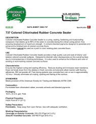
Drawings & Detail PlansInstallation GuidelinesTypical Bridge Approach ZonesNote: Where significant amounts of runoff collected byditches, utilize sedimentation ponds to slow flow anddeposit sediment before flowing from right of way intotreed areas.Sediment Logs securedat outlet.DETAIL FDETAIL ISilt fence1 - 4m x 1m x 1mgabion basket retention wingSilt FenceDETAIL HSedimentationPond (1m depth)Road BridgeRip Rap to high water elev.RoadDETAIL GDETAIL EFlowWhere ditches present installsediment logs to dissipateflow and collect siltSilt fenceNote: Additional Silt Fence should be utilizedin all areas where construction activities mayleave disturbed areas exposed and subject to erosion.This is especially important close to stream areas.Note: Details shown are typical and may need tobe modified to suit field situations. Please use this planas a guide to implement the suitable components.TMFigure 1: Erosion/Sediment ControlNTSA Division of <strong>Brock</strong> <strong>White</strong> Canada Companywww.<strong>Brock</strong><strong>White</strong>.com C - 1
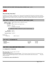
Drawings & Detail PlansInstallation Guidelineswooden posts or steel“T”- posts600 mmNote: Silt Fenceflap anchoredin key trench orburied to preventunderflow.600 mmDETAIL J: Silt Fence Standard DetailTMA Division of <strong>Brock</strong> <strong>White</strong> Canada Company32” page wire withAGES Premium wovenSilt FenceFabric clipped to page wireat 450mm interval along topmid point and bottomOptional 1”x 2” Strapping200 mm key trenchDETAIL K: Wire Supported Silt FenceFigure 2: Supported Silt FenceNTSC - 2 BURNABY • LANGLEY • PRINCE GEORGE • EDMONTON • CALGARY • LLOYDMINSTER • SASKATOON • REGINA • WINNIPEG • THUNDER BAY
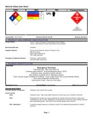
Drawings & Detail PlansInstallation GuidelinesTypical Sediment Log Ditch ApplicationTMA Division of <strong>Brock</strong> <strong>White</strong> Canada CompanyFigure 3: Ditch Sediment ControlNTSRoadLevelFlowDitch GradeStandard SpacingWooden Stakeswww.<strong>Brock</strong><strong>White</strong>.com C - 3
Drawings & Detail PlansInstallation GuidelinesConstruction Specifications:- The height of a silt fence shall not exceed 36 inches (0.9 m).Storage height and ponding height shall never exceed 18 inches (0.5m).Smile Formation- To minimize erosion, install silt fence at the head of a slope to slowvelocity and create a large storage area.SLOPE DIRECTION SLOPE DIRECTION- Silt fences placed at the toe of a slope shall be set at least 6 feet (1.8m) from the toe in order to Increase ponding volume.- The fence line shall follow the contour of the slope as closely aspossible.1) CONSTRUCT FIRST LEG- The ends of the fence should be turned uphill.-A key trench must be excavated along the the contour on theupslope side of the barrier.- Posts should be utilized, properly spaced and driven intocompacted soil. If a fence reinforced with page wire is required, 6’steel t-posts are used. Otherwise, wooden posts are used.- The fabric must be extended into the trench and stapled or wireddirectly to the posts. If reinforced fence is being used, then the fabricmust be stapled or wired to the page wire.- Fabric should be attached to the posts with three diagonal ties(plastic or wire).- Filter fabric shall not be stapled to existing trees.- Post spacing shall be 2m-3m, based on the strength of the fabricused.- The trench is then backfilled and the soil is compacted over the filterfabric to ensure that no gaps exist between the ground and fabric.Silt fences do not work without proper trenching andcompacted backfill.- Use of a reinforced fence is recommended for applications with highflow volume, adverse soil conditions (including heaving), high windconditions, or any other environmental or construction condition thatwould make the fence susceptible to failure.SLOPE DIRECTION2) CONSTRUCT MAIN DAMSLOPE DIRECTION3) CONSTRUCT SECOND LEGAttaching Two Sections of Silt Fencing:1) The end post of the second fence must first be placed inside the endpost of the first.2) Rotate the posts clockwise together at least 100o to create a seal.3) Both posts must be driven into the ground and the flap buried at adepth of about 25 cmInspection and Maintenance:- Silt fences and filter barriers shall be inspected weekly and after each significant storm (1inch, or 24.5 mm) in 24 hours. Any required repairs shall be made immediately.- Sediment should be removed when it reaches 1/3 height of the fence of 9 inches (0.3 m)maximum- The removed sediment shall conform to the existing grade and be vegetated or otherwisestabilized.- Silt fences shall be removed when they have served their useful purpose, but not before theupslope area has been permanently stabilized and any sediment stored behind the siltfence has been removed.TMFigure 4:Silt Fence InstallationA Division of <strong>Brock</strong> <strong>White</strong> Canada CompanyC - 4 BURNABY • LANGLEY • PRINCE GEORGE • EDMONTON • CALGARY • LLOYDMINSTER • SASKATOON • REGINA • WINNIPEG • THUNDER BAY
Propex GeotextilesInstallation GuidelinesINTRODUCTIONPropex’s Geotex family of geotextiles can enhance the performance of paved and unpavedroadways, parking lots, airports, loading docks, and storage areas through separation/stabilization of the roadway structure. the geotextiles provide three important functions;separations/stabilization, drainage, and reinforcement. The fabric serves as a permeableseparation/stabilization layer, preventing the aggregate and subgrade soils from intermixingwhile allowing the passage of water. The geotextile also enhances the structural propertiesof the subgrade and the roadway aggregate to minimize the coast of the road structure.The successful use of geotextiles in these applications requires proper installation. The fourbasic steps of proper installation include:• Subgrade preparation• Geotextile placement• Aggregate placement• Aggregate compactionGeotex stabilization geotextiles can be used in most weather and temperature conditions.Adequate planning and preparation for each installation step will speed construction andensure good performance.These guidelines provide recommendations for installation of geotextiles in separation/stabilization applications.The guidelines are intended to assist the contractor responsible for installation of thespecified geotextile.They are to be considered general guidelines, appropriate for common constructionconditions. Specific site conditions, design requirements, or other variables may requiremodification to these guidelines.Subgrade PreparationInitially, the site should be cleared of tree stumps, large stones, and other sharp objects thatcould puncture the fabric. This step should be performed regardless of subgrade strength.Roadway subgrade preparation typically involves removal of all vegetation, roots, and topsoil.Localized soft or otherwise unsuitable subgrade areas may be required to be excavatedand backfilled with select material. In some very soft soil applications, it is beneficial to leavevegetation, roots, and topsoil in place to limit subgrade soil disturbance and loss of strength.www.<strong>Brock</strong><strong>White</strong>.com C - 5
Propex GeotextilesInstallation GuidelinesGeotextile PlacementTwo people can easily place Geotex separation/stabilization geotextiles. The fabric should berolled out onto the subgrade beginning at a point that allows easy access for constructionequipment yet is consistent with the layout plan. On very soft subgrades the fabric layout andaggregate placement should begin on firm soil on the site perimeter, to establish an “anchorpoint.” From there the fabric can be rolled onto softer sections. The geotextile should not bedragged across the subgrade. the geotextile is usually laid in the direction of construction traffic;however, specific project dimensions may alter this layout. Geotextile panels should beoverlapped both site-to-side and end-to-end, in the direction of aggregate placement. Therecommended overlap ranges from 1.5 to 3 feet, depending on subgrade strength. Overlaprecommendations are provided in Table 1.Alternatively, adjacent fabric edges can be sewntogether rather than overlapped. Sewn seams must beused when the geotextile provides significant tensilereinforcement. This is the case, for example, when thesubgrade is very soft (CBR
Propex GeotextilesInstallation GuidelinesAggregate PlacementAggregate is placed and spread on the fabric using conventional construction practices andequipment. Soil, rocks, or pins should be used to anchor the leading edge of the fabric toprevent it from lifting during placement of the first aggregate lift. The aggregate is typicallyback-dumped onto the geotextile, as the truck should not drive directly on the fabric. Theaggregate is then spread over the geotextile. A tracked bulldozer is best used for thisoperation. Low ground pressure models are recommended for work on soft subgrades.Lift thickness should not be less than 6 inches. The first lift should be as thick as necessaryto limit rutting to less than 4 inches. during spreading, the bulldozer should blade into theload and slightly upward to prevent stressing the fabric. This procedure should be followedfor each load until the fabric is completely covered. The dozer operator can determine whichareas may need additional aggregate for good stability by observing aggregate layer rutting.On very soft subgrades, care should be taken during aggregate placement to ensure that thefabric is not moved out of position nor the subgrade overstressed. Over some very soft soilconditions, “mud waves” may appear during or subsequent to aggregate placement. Mudwaves result from overstressing the subgrade during fill placement, causing the subsurfacesoil to move away and up from the loaded area. They are normally not a problem if they donot heave above the surface of the aggregate base. If severe mud waves are anticipated aPropex representative can provide information on construction procedures to minimize theiradverse effects.Sudden stops or turns by equipment operating over the geotextile should be avoided. Undertypical conditions, vehicles should not be allowed to drive directly on the geotextile. If spaceconstraints make this impractical, the possible damage from direct vehicle contact should beevaluated on a test section of the geotextile. If the fabric is damaged such that it cannot fulfillproject requirements, a more damage-resistant geotextile should be specified. If the fabric isdamaged during installation, the damaged section should be exposed and a patch of fabricplaced over it. the patch should be large enough to overlap onto undamaged areas asrecommended in Table 1. The aggregate is then replaced and compacted.Aggregate CompactionThe aggregate must be compacted as required by the project specifications. The aggregateshould be initially compacted by “walking” the tracked bulldozer back and forth over theaggregate until reasonable stability is obtained. Final compaction is achieved by rolling thearea with a vibratory compactor, first without vibration for several passes and then with fullvibration. Any weak areas found during final compaction usually indicate inadequateaggregate thickness in those locations. Do not grade ruts down; simply fill with additionalaggregate and compact to the specified density. This also applies to any future rutmaintenance that might be required.Construction MonitoringIt is important that the construction conditions and process be monitored. If the actualsubgrade has lower strength than that assumed for design, the structural section designthicknesses must be re-evaluated. Observation of rutting of the aggregate layer, for example,can pinpoint weak subgrade areas, allowing design adjustments to be made on site ifnecessary. One advantage of an unpaved road is the ability to identify and resurface weakareas to avoid over-designing the entire road. Aggregate base placed for a new pavementmay also be monitored for weak areas and corrected before the pavement layer(s) is placed.www.<strong>Brock</strong><strong>White</strong>.com C - 7
Propex GeotextilesInstallation GuidelinesARMORMAX Anchored Reinforced Vegetation SystemWOVEN THREE-DIMENSIONAL HPTRM PROTECTIONLAYER FEATURING X3® FIBER TECHNOLOGYUnique X3 fiber shape provides over 40% more surfacearea than conventional fibers to capture the moisture, soiland water required for rapid vegetation growthExhibits extremely high tensile strength as well assuperior interlock and reinforcement capacity with bothsoil and root systemsMaximum ultraviolet protection for long-term design lifeNetless, rugged material construction stands up to thetoughest erosion applications where high loading and/or highsurvivability conditions are requiredEARTH PERCUSSION ANCHORS TO SECURETHE MAT TO THE GROUNDMade of corrosion resistant aluminum alloy, gravitydie cast and heat treated to give considerable increasein mechanical strength and curability both duringinstallation and in serviceConnected to a threaded rod or stainless tendon tofully enhance corrosion resistance particularly at thesoil/air interfaceAs the loadexerted onsoilPlatethe soil byHPTRMthe ArmorMaxsystemincreases, abody of soilEarth percussion anchor above theanchor is compressed and provides resistance to anyfurther anchor movement — permanently securing themat to the groundCompressedARMORMAX NON-STRUCTURAL APPLICATIONSThe figures below illustrate the ArmorMax system for non-structural applications. The system is comprised of the HPTRM andtypically Type 2 earth percussion anchors.LEVEE ARMORINGARID/SEMI-ARID STORM WATER CHANNELSCANAL, STREAM AND RIVER BANK PROTECTIONARMORMAX STRUCTURAL APPLICATIONThe figures below illustrate the use of ArmorMax in a structural application for surficial slope stabilization. The system iscomprised of the HPTRM and Type 1A or 1B earth percussion anchors as specified by the project engineer.SHALLOW PLANE FAILUREAPPLY ARMORMAX SYSTEMVEGETATION GROWTHC - 8 BURNABY • LANGLEY • PRINCE GEORGE • EDMONTON • CALGARY • LLOYDMINSTER • SASKATOON • REGINA • WINNIPEG • THUNDER BAY
American Excelsior CompanyInstallation GuidelinesInstallation InstructionsSlope Application1) Prepare soil so that area is smooth, then add fertilizerand lime as required.2) Start by stapling the blanket at the top of the slope in a6” deep x 6” wide trench. Backfill & compact trench sothat the water will flow evenly onto the blanket.3)(a) Roll blanket down the slope, or (b) horizontallyacross slopes < 50’ insuring soil blanket contact.4) Overlap edges of blanket a minimum of 2” withparallel blankets.5) If more than one blanket is needed for the run thenoverlap adjoining ends a minimum of 4” shingle style.Staple overlap areas with staggered pattern with staples.Channel Application1) Prepare soil so that area is smooth, then add seed,fertilizer & lime as required.2) Start by spaling the blanket at the top of the channelin a 6” deep x 6” wide trench. Backfill & compact trenchso that the water will flow evenly onto the blanket.3) Roll center blanket in the bottom of the channel &place 4 staples per square yard. Follow staple patternon back to determine pattern for your situation.4) Place adjoining ends overlapping 6” securing theoverlap with a double row of staplesstaggered 4” apart. Overlap edges of blanket aminimum of 6” with parallel blankets.5) The full length of the blanket at the top of the channel must beanchored in a 6” wide x 6” deep trench then backfilled & compactedafter placing staples in the trench 3ft. apart. Insure compacting so that water canflow evenly onto the blanket from the sides of the channel.6) Place a double row of staggered staples 4” apart every 33ft.7) Insure blanket is placed on side banks of channel 1ft. higher than expected water flow.8) At the terminal end of the channel, the blanket must be anchored such that the water will flow to thedesired area. If the end of the channel is a culvert, the blanket must be placed underthe culvert & secured with staples 4” apart in a staggered pattern.Shoreline Application1) If possible lower level of water for ease of application.If water is artificially lowered before application, installblanket before water level is raised.2) Prepare soil so that area is smooth then add seed,fertilizer & lime as required.3) Start by stapling the blanket at the top of the slope in a6” deep x 6” wide trench. Backfill & compact trench sothat the water will flow evenly onto the blanket.4)(a) for slopes over 50ft. in length lay blanket downthe slope. (b) for slopes < 50ft lay horizontally.5) Overlap blanket 4”, staple through both blankets ofoverlapped area with one staple every 12”6) The bottom of the blanket that falls below the water level must be placed in a trench that is 12” deepand 6” wide, stapled, backfilled, & compacted.7) If the soil is loose, the use of longer staples may be required.www.<strong>Brock</strong><strong>White</strong>.com C - 9
American Excelsior CompanyInstallation GuidelinesC - 10 BURNABY • LANGLEY • PRINCE GEORGE • EDMONTON • CALGARY • LLOYDMINSTER • SASKATOON • REGINA • WINNIPEG • THUNDER BAY
American Excelsior CompanyInstallation Guidelineswww.<strong>Brock</strong><strong>White</strong>.com C - 11
Propex Landlok & TRMsInstallation GuidelinesBefore you BeginIt is important to follow these installation guidelines for a successful project. (Note:Construction shall be performed in accordance with the specific project biddocuments, construction drawings, and specifications). In addition, we suggest thata pre-installation meeting be held with the construction team and a representativefrom Propex. Propexsuggests that installation monitoring of our TRMs and HPTRMs be performed by aqualified independent third party.Site Preparation• Grade and compact area of TRM/HPTRM installation as directed and approved byEngineer. Subgrade shall be uniform and smooth. Remove all rocks, clods,vegetation or other objects so the installed mat will have direct contact with soilsurface.• Prepare seedbed by loosening the top 2-3 inches minimum of soil• Incorporate amendments such as lime and fertilizer and/or wet the soil if needed.• Do not mulch areas where mat is to be placed.Seeding• Apply seed to soil surface before installing mat. Disturbed areas shall be reseeded.• When soil filling, first install the mat, apply seed and then soil-fill.• Consult project plans and/or specifications for seed types and application rates.C - 12 BURNABY • LANGLEY • PRINCE GEORGE • EDMONTON • CALGARY • LLOYDMINSTER • SASKATOON • REGINA • WINNIPEG • THUNDER BAY
Propex Landlok & TRMsInstallation GuidelinesInstallation on Stable Soil Slopes• Excavate a 12” x 6” minimum longitudinal anchor trench 2-3 ft. over crest of slope.• Install top end of mat into trench and secure to bottom using suggested ground anchoringdevices spaced every 12” minimum. Backfill and compact soil into trench.• Unroll mat down slope. Landlok 1051 shall have the geotextile on bottom.• Overlaps shall be 6” minimum and anchored every 18” minimum along the overlap. Secureusing suggested ground anchoring devices shown below for appropriate frequency andpattern. Overlaps are shingled away from prevailing winds.• Unroll mat in a manner to maintain direct contact with soil. Secure mat to ground surfaceusing ground anchoring devices.• Excavate a 12” x 6” key anchor trench at toe of slope• Place bottom end of mat into key anchor trench at toe of slope and secure to bottom oftrench using suggested ground anchoring devices spaced every 12” minimum. Backfill andcompact soil into trench.• If the potential for standing and/or flowing water exists at the toe of slope, the key anchortrench at the toe detail is not sufficient. Consult the project engineer for the appropriatedetail.• Irrigate as necessary to establish/maintain vegetation. Do not over-irrigate.Figure 1.Installation ofpermanent turfreinforcement maton slope- Overlaps 6” min.- Space anchors 18”along overlapsdown the slope- Anchor pattern shallbe in accordancewith the “anchorpattern guide”www.<strong>Brock</strong><strong>White</strong>.com C - 13
Propex Landlok & TRMsInstallation GuidelinesFigure 2.Longitudinal anchortrench at top of slope- space anchors 12”along bottom oftrenchFigure 3.Key anchor trenchat toe of slopeInstallation in Storm Water Channels• Excavate an initial anchor trench 12” min. deep and 12” min. wide across the channel atdownstream end of project. Deeper initial anchor trench is needed in channels that havethe potential to scour.• Excavate longitudinal anchor trenches 12” min. deep and 6” min. wide along both sides ofthe installation to bury edges of mat. The trench shall be located 2-3ft. over crest of slope.• Place roll end into the initial anchor trench and secure with anchoring devices at 12” min.intervals. Position adjacent rolls and secure in anchor trench in same manner. Backfill andcompact soil into trench.• Unroll mat in the upstream direction over the compacted trench.• Continue installation as described above, overlapping adjacent rolls as follows: Roll edge6” min. with upslope mat on top. Secure with one row of ground anchoring devices on 12”min. intervals. Roll end 12” min. with upstream mat on top. Secure with two rows of groundanchoring devices staggered 12” min. apart on 12” min. intervals.• Fold and secure mat rolls snugly into intermittent check slots. Lay mat in the bottom andfold back against itself. Anchor through both layers of blanket or mat at 1ft. intervals thenbackfill and compact soil. Continue rolling upstream over the compacted slot to the nextcheck slot or terminal anchor trench. Check slots are placed at 25 to 30ft. intervalsperpendicular to flow.C - 14 BURNABY • LANGLEY • PRINCE GEORGE • EDMONTON • CALGARY • LLOYDMINSTER • SASKATOON • REGINA • WINNIPEG • THUNDER BAY
Propex Landlok & TRMsInstallation GuidelinesFigure 4. Installation of TRMs & HPTRMs in storm water channelsFigure 5. Initial anchor trench (downstream) detail• Alternative method to the intermittentcheck slot is the simulated check slot.This method includes placing twostaggered rows of anchors on 4” centersat 30ft. intervals.• Excavate terminal anchor trench 12”wide x 12” deep min. across thechannel at the upstream end of theproject. Deeper terminal anchor trenchis needed in channels that have thepotential for scour.• Anchor, backfill & compact upstreamend of mat in 12x12” min. terminalanchor trench. Unroll mat in downstreamdirection over compacted trench with aminimum 2ft. lap.• Secure mat using suggested groundanchoring devices for appropriatefrequency and pattern• Seed and fill with soil for enhancedperformance.• When using Landlok 1051, seed afterinstalling mat and then fill with soil.• Irrigate as necessary to establish/maintain vegetation. Do not over irrigate.Figure 6. Longitudinal anchor trench detailNOTE: If you encounter roll with factoryoverlap, install factory seam such that itshingles in the direction of the flow of water.www.<strong>Brock</strong><strong>White</strong>.com C - 15
Propex Landlok & TRMsInstallation GuidelinesFigure 7. Overlap at roll edgeFigure 8. Overlap at roll endFigure 9. Intermittent check slot (channels)Figure 10. Simulated check slotFigure 11. Terminal anchor trench (upstream) detailC - 16 BURNABY • LANGLEY • PRINCE GEORGE • EDMONTON • CALGARY • LLOYDMINSTER • SASKATOON • REGINA • WINNIPEG • THUNDER BAY
Propex Landlok & TRMsInstallation GuidelinesSpecial Transition GuidelinesRock Riprap• Excavate an anchor trench 12” x 12” minimum at the transition between the mat and the rockriprap• Place roll end into anchor trench and secure with suggested anchoring devices at 12”minimum intervals. Position adjacent rolls and secure in anchor trench in same manner.• Backfill the anchor trench with rock riprapConcrete• Alternative 1: Concrete Apron. Place ready mixed concrete directly onto a 3ft. wide minimumstrip of mat.• Alternative 2: Excavate an anchor trench 12” x 12” minimum at the edge of the concretestructure. Place roll end into anchor trench and secure with suggested anchoring devices at12” minimum intervals. Position adjacent rolls and secure in anchor trench in same manner.Backfill trench with concrete slurry.• Alternative 3: Bolt to Structure (HPTRMs Only) Cast threaded dowel in fresh ready mixconcrete or install expanding bolt into cured concrete. Then affix HPTRM with washer(minimum 2” in diameter) or batten strip and bolt.Pipe Inlets/Outlets (HPTRMs Only)• Review the construction drawings and project specifications to evaluate the required area tobe treated.• Excavate an anchor trench 12” x 12” minimum above the pipe to bury end of HPTRM roll.The trench shall be located a minimum 2-3ft. above the pipe inlet/outlet.• Backfill and compact soil in trench.• Cut HPTRM to meet project requirements, slope length and pipe diameter.• Unroll HPTRM down the slope and secure around pipe circumference with ground anchoringdevices spaced 6” minimum. Also, the HPTRM can be secured around the pipe in a 12” x 12”minimum trench filled with concrete slurry.Ground Anchoring Devices• Ground anchoring devices are used to secure the mat to the soil using the suggested anchordevice at a minimum frequency and pattern.• U-shaped wire staples or metal geotextile pins can be used to anchor mat to the groundsurface. Wire staples should be a minimum thickness of 8 gauge. Metal pinsshould be at least 0.20” diameter steel with a 1.5” steel washer at the head of the pin. Wirestaples and metal pins should be driven slush to the soil surface. All anchors should bebetween 6-24” long and have sufficient ground penetration to resist pullout. Longer anchorsmay be required for loose soils. Heavier metal stakes may be required in rocky soils.www.<strong>Brock</strong><strong>White</strong>.com C - 17
Propex Landlok & TRMsInstallation GuidelinesTable 1. Suggested ground anchoring device selection.Table 2. Suggested lengths of ground anchoring devices.Anchor Pattern GuideThe shaded areas in thediagram provide anchorsuggestions based on slopegradient and/or anticipatedflow conditions. When thecorrect number of anchors hasbeen determined, refer to thefour illustrations below toestablish anchor pattern.Increased anchoring may berequired depending upon siteconditions.C - 18 BURNABY • LANGLEY • PRINCE GEORGE • EDMONTON • CALGARY • LLOYDMINSTER • SASKATOON • REGINA • WINNIPEG • THUNDER BAY
Propex Landlok & TRMsInstallation GuidelinesNOTE: For clarity, perspective view does notshow all anchors.Transverse JointPlaced every 8 m (26.2 ft)(Perpendicular to Flow Direction)(Typ)Terminal Anchor TrenchPermanent Turf Reinforcement MatOverlap Joint(Typ)Anchor Pattern(Typ)Key Trench(Typ)Initial Anchor Trench600 mm (2 ft)MinKey TrenchConcentrated FlowCenterline - Channel or SwaleHinge PointHinge pointPERSPECTIVEPERMANENT TURF REINFORCEMENT MATIN TRAPEZOIDAL CHANNEL OR SWALEwww.<strong>Brock</strong><strong>White</strong>.com C - 19
Propex Landlok & TRMsInstallation GuidelinesC - 20 BURNABY • LANGLEY • PRINCE GEORGE • EDMONTON • CALGARY • LLOYDMINSTER • SASKATOON • REGINA • WINNIPEG • THUNDER BAY
AEC Sediment Log Channel SpacingInstallation GuidelinesNOTES: 1. Spacing of curlex Sediment Logs is Calculated by: [Distance between channel botton and top of installed CurlexSediment Log (ft)/Channel gradient (%) * 100=Curlex Sediment Log Spacing (ft) 2. Curlex Sediment Log Spacing (ft) * 0.3048 =Curlex Sediment Log Spacing (m) 3. Min. installed heights sued for determining spacing values in table. Min. installed heights of9” & 12” Curlex Sediment Logs are 20.8cm (8.2 in) & 27.9 cm (11.0 in), respectively.www.<strong>Brock</strong><strong>White</strong>.com C - 21
ScourStopInstallation GuidelinesANCHORING REQUIREDCohesive SoilsNon-Cohesive SoilsAt a GlanceLay the ScourStop mats overthe designated area, centeringthe mat layout with thedischarge point, and parallelto the flow direction.As the mats are semi rigid,anchors may be located inregions or centers of regionsof the mat, rather than directlyin the corners, and on theedges.An anchor could be located6-8” in from an edge, yet stillfirmly hold down that sameedge.The objective is to have themat flush with the surface,and minimal gaps betweenthe surface and the matwhere water could concentrateand cause erosion.Install at lease 5 anchors persheet of transition mat, in a3-2-3 configuration, with thedownstream 3 anchors alsoanchoring the leading edgeof the next mat. Use moreanchors if necessary to insurea flush installation (propergrade preparation shouldminimize this need).Possibly stand on differentregions of the mat beforeanchoring to determine wherethe anchors would be bestlocated to minimize the needfor extra anchors. Standardpackaging provides 6 anchorsper mat.Transition mats doubled upin the immediate scour areaof 36+ inch discharge pipeshave shown added protection.C - 22 BURNABY • LANGLEY • PRINCE GEORGE • EDMONTON • CALGARY • LLOYDMINSTER • SASKATOON • REGINA • WINNIPEG • THUNDER BAY
ScourStopInstallation GuidelinesANCHORINGINSTALL <strong>GUIDE</strong>www.<strong>Brock</strong><strong>White</strong>.com C - 23
Mat, Inc.Installation GuidelinesRevegetation Products Performance ChartThis Product Performance Chart is based on field applictations ofMat products by dedicated and eprformance minded applicators.This Performance Chart is meant as a guide only, location conditions willrequire attention to “Best Management Practices” for a specification. On slope lengths greater than twentyfeet slope interruption devices may be required.Based on rates in pounds-per-acre. (lbs./acre)A. Multiply total sq. ft. to be covered, by desiredMulch rate in lbs./acre.B. Divide the answer to A by 43,560 (sq.ft. in 1 acre)C. Divide B by the number of lbs./bag = # of bags15,000 sq.ft. x 2,000 lbs./acre =30,000,00030,000,000 divided by 43,560 =688 lbs. mulch688 divided by 50 lb. bags =13.77 bags2000 sq. meters x 2,000 kgs./hectare =3,400,0003,400,000 divided by 10,000 =340 kgs. mulch340 kgs. divided by 22.6 kgs./bag =15.04 bagsC - 24 BURNABY • LANGLEY • PRINCE GEORGE • EDMONTON • CALGARY • LLOYDMINSTER • SASKATOON • REGINA • WINNIPEG • THUNDER BAY
Mat, Inc.Installation GuidelinesErosion Control Products Performance ChartThis Product Performance Chart is based on field applictations ofMat products by dedicated and eprformance minded applicators.Erosion Control This Performance Products Chart is meant Performance as a guide only, location Chart conditions willrequire attention to “Best Management Practices” for a specification. On slope lengths greater than twentyThis Product Performance Chart is based on field applications of Mat products by dedicated and performance minded applicators.feet This Performance slope interruption Chart is meant devices as a guide only, may location be required.conditions will require attention to "Best Management Practices" for a specification. On slope lengthsProductCategory®Flex GuardSpray Guard ®6:1Slope Length4:1Slope Length3:1Slope Length2.5:1Slope Length0-30’ 30-60’ 60-120’ 0-30’ 30-60’ 60-120’ 0-30’ 30-60’ 60-120’ 0-30’ 30-60’ 60-120’ 0-30’ 30-60’ 60-120’ 0-30’ 30-60’ 60-120’3000#/Acre4000#/AcreSoil Guard ® 3000#/Acre4000#/Acre3000#/Acregreater than twenty feet slope interruption devices may be required.2:1Slope Length3500#/Acre1:1Slope LengthArea Coverage Per Load For Mat Inc. Erosion Control ProductsTank Capacity(in Gallons)3005008001000120025003000# of Bags Volume Coverage Area Coverage Area(50 lbs.bags) (Gals) (Sq.Ft.)(acres)35810122530324540864108012962700324021753,6105,8007,2508,70018,15021,750.017.083.133.166.200.417.500Based on rates-per-acre of 3000 lbs. “Guard” products can be mixed at 50 lbs. per 100 gals. water.Based Based on rates on rates in in pounds-per-acre. (lbs./acre) (lbs./acre)A. Multiply total sq. ft. to be A. Multiply total sq. ft. to be covered, by desiredby desired mulch rate in lbs./acre.Mulch rate in lbs./acre.B. Divide the answer to A by 43,560. (sq.ft. in 1 acre)B. Divide the answer to A by 43,560 (sq.ft. in 1 acre)C. Divide B by the number of lbs./ bag = # no. of bags.C. Divide B by the number of lbs./bag = # of bagsExample:15,000 sq. sq.ft. x 2,000 x 2,000 lbs./acre lbs./acre = 30,000,000 =30,000,00030,000,000 43,560 = 688 lbs. mulch30,000,000 688 50 divided lbs./bag = 13.77 by 43,560 bags =688 lbs. mulch688 divided by 50 lb. bags =13.77 bagsMetric Example:2000 2000 sq. meters sq. meters x 2,000 kgs./hectare x 2,000 = 3,400,000 kgs./hectare =3,400,0003,400,000 10,000 = 340 kgs. mulch3,400,000 340 kgs. 22.6 divided kgs./bag by = 15.04 10,000 bags =340 kgs. mulch340 kgs. divided by 22.6 kgs./bag =15.04 bags* As defined by the Erosion Control Technology Council (ECTC).www.<strong>Brock</strong><strong>White</strong>.com C - 25
Encap - Pam12Installation GuidelinesPAM-12 Plus Hydraulic ApplicationApplication Rates for PAM-12SlopePounds/AcreNo Slope – 6:1 450 – 6006:1- 4:1 600 – 10004:1 – 3:1 1000 – 15003:1 – 2:1 1500 - 3000** Slope, soil type, and time of year will affect therecommended PAM-12 application and rate.1000 lbs. per acreMethods of Application1. Mechanical or Jet Agitation Hydroseeder2. PTO Driven Broadcast Spreaders (Seeders orFertilizer)3. Straw Blowers4. Fixed Wing or HelicopterHydraulic Application References:PAM-12 Plus – used alone as the soil stabilizerTank Capacity(Gallons)PAM-12 Plus(Total lbs.)Bags(50 lbs.)Coverage Area(3000 sq.ft./bag)300 300 6 18,000500 500 10 30,000800 800 16 48,0001200 1200 24 72,0001500 1500 30 90,0002500 2500 50 150,0003000 3000 60 180,000PAM-12 Plus – as tackifier, mix with cover mulchTank Capacity(Gallons)PAM-12 Plus(Total lbs.)Cover Mulch(Total lbs.)300 100 50 6000900 300 150 18,0001500 500 250 30,0003000 1000 500 60,000Coverage Area(Sq.Ft.)ENCAP,LLC recommends consultation with local distributor’s sales staff if there are anyquestions about the site.C - 26 BURNABY • LANGLEY • PRINCE GEORGE • EDMONTON • CALGARY • LLOYDMINSTER • SASKATOON • REGINA • WINNIPEG • THUNDER BAY
Firestone - PondGardInstallation GuidelinesPondGard Non-Reinforced EPDMGeomembrane (Black)DESCRIPTIONFirestone PondGard non-reinforced EPDM Geomembrane is a cured single-ply pond lininggeomembrane.PREPARATION OF SUBSTRATES:1.) Substrates must be clean, dry, smooth, and free of sharp edges, fins, loose or foreign materials, oil,grease, and other materials that may damage the geomembrane.2.) All roughened surfaces that can damage the geomembrane shall be repaired as specified to offer asmooth substrate.3.) All surface voids greater than 1/4” (6.3mm) wide shall be properly filled with an acceptable fillmaterial.METHOD OF APPLICATION1.) PondGard non-reinforced EPDM Geomembrane must be installed in accordance with currentPondGard specifications, details and workmanship requirements.STORAGE1.) Store away from sources of punctures, and physical damage.2.) Assure that structural decking will support the loads incurred by material when stored on rooftop.The deck load limitations should be specified by the project designer.3.) Store away from ignition sources as geomembrane will burn when exposed to open flame.PACKAGINGThicknessWidthsLengthsWeight.45”(1.1mm).060”(1.5mm)7.5ft* (2.3m*)9ft** (2.7m**)10ft (3m)20ft (6.1m)25ft (7.6m)40ft (12.2m)50ft (15.2m)7.5ft* (2.3m*)9ft** (2.7m**)10ft (3m)20ft (6.1m)50ft (15.2m)100ft (30.5m)200ft (61m)50ft (15.2m)100ft (30.5m)0.29 lb/sf (1.4 kg/m 2 )0.40lb (1.9 kg/m 2 )*Packaged 2 panels per roll.**Available in 100’ (30.5m) rolls only.PRECAUTIONARY DATA:1.) Take care when moving, transporting, handling, etc. to avoid sources of punctures and physicaldamage.2.) Isolate waste products, such as petroleum products, greases, oils (mineral and vegetable) andanimal fats from the PondGard geomembrane. Contact Firestone Specialty Products Department forspecific recommendations.3.) Refer to Material Safety Data Sheets (MSDS) for safety information.www.<strong>Brock</strong><strong>White</strong>.com C - 27
Conversion TablesInstallation GuidelinesEnglish UnitsMetric Units12 inches = 1 foot Milla = 1/10003 feet = 1 yard Centi = 1/1005,280 feet = 1 mile Kilo = 1,000144 square inches = 1 square foot Mega = 1,000,0009 square feet = 1 square yard Used with meters, liters, grams, etc.43,560 sq ft = 1 acre1728 cubic inches = 1 cubic foot27 cubic feet = 1 cubic yard8 fluid ounces = 1 cup2 cups = 1 pint2 pints = 1 quart4 quarts = 1 gallon1 gallon = 231 cubic inches1 cubic yard = 202 gallons7.48 gallons = 1 cubic footMeasurement ConversionsMeasurement ConversionsIf You Have Multiply By To Find If You Have Multiply By To Findinches 1000 mils liters 33.8141 fluid ouncesmils 0.001 inches in 3 0.004329 gallons (us)inches 25.4 millimeters cm 3 0.06102 in 3inches 2.54 centimeters in 3 16.39 cm 3centimeters 0.3937 inches in 3 0.00058 ft 3inches 0.0254 meters ft 3 1728 in 3yards 0.9144 meters ft 3 0.02832 in 3meters 1.0936 yards m 3 35.314 ft 3meters 39.37 inches ft 3 0.037 yd 3in 2 6.452 cm 2 yd 3 27 ft 3cm 2 0.155 in 2 m 3 1.308 yd 3ft 2 144 in 2 yd 3 0.7646 m 3in 2 0.00694 ft 2 w/c ratio 11.3 gal. water/bag of cementft 2 929.03 cm 2 gal. water/bag of cement 0.0885 w/c ratioft 2 0.0929 m 2 lb/ft 2 4.88 kg/mcm 2 0.00108 ft 2 kg/m 2 0.2048 lb/ft 2yd 2 0.8361 m 2 ft 2 /gal 0.02454 m 2 /literyd 2 0.0002066 Acres m 2 /liter 40.75 ft 2 /galm 2 1.196 yd 2 lbs 0.0005 tons (US)m 2 10.76 ft 2 tons (US) 2000 lbsacres 43,560 ft 2 tons (US) 0.9072 tons (METRIC)acres 4840 yd 2 kg 1000 gfluid ounces 1.805 in 3 g 0.001 kgin 3 0.554 fluid ounces g 0.0022 lbsin 3 0.01639 liters lbs 453.5924 gliters 61.024 in 3 lbs 0.4536 kggallons (US) 231 in 3 kg 2.205 lbsfluid ounces 0.03215 quarts mpa 145 psiquarts 32 fluid ounces psi 0.006895 mpagallons (US) 4 quartsquarts 0.25 gallons (US)gallons (US) 128 fluid ouncesfluid ounces 0.00781 gallons (US)fluid ounces 0.02957 litersD - 1BURNABY • LANGLEY • PRINCE GEORGE • EDMONTON • CALGARY • LLOYDMINSTER • SASKATOON • REGINA • WINNIPEG • THUNDER BAY
Conversion TablesInstallation GuidelinesApproximate Conversions to Metric Measures from English UnitsWhen You Know Multiply By To Findinches 25.4 millimetersinches 2.54 centimetersfeet 30.5 centimetersyards 0.91 metersmiles 1.61 kilometersApproximate Conversions to English Units from Metric MeasuresWhen You Know Multiply By To Findmillimeters 0.039 inchescentimeters 0.39 inchesmeters 3.28 feetmeters 1.09 yardskilometers 0.62 milesApproximate Conversions to Metric Measures from English UnitsWhen You Know Multiply By To Findsq. inches 6.452 sq. centimeterssq. feet 0.092 sq. meterssq. yards 0.836 sq. metersacres 0.4047 hectaresq. miles 2.59 sq. kilometersApproximate Conversions to English Units from Metric MeasuresWhen You Know Multiply By To Findsq. centimeters 0.155 sq. inchessw. meters 1.196 sq. yardshectares 2.471 acressq. kilometers 0.386 sq. milesApproximate Conversions to Metric Measures from English UnitsWhen You Know Multiply By To Findcubic inches 16.0 millimetersfluid ounces 29.6 millimeterscups 0.24 literspints 0.473 litersquarts 0.946 litersgallons 3.791 literscubic feet 0.028 cubic meterscubic yards 0.76 cubic meterscubic feet 28.3 literscubic yards 764.5 literswww.brockwhite.comD - 2
OUR MATERIALS HELP BUILD THE PROJECT.OUR WHOLE COMPANY MAKES IT A SUCCESS.www.<strong>Brock</strong><strong>White</strong>.comBurnaby2450 Alpha Ave, V5C 5L6Phone 604-299-8551Fax 604-299-33431-800-665-6200Lloydminster4806 - 62 Avenue, T9V 2E9Phone 780-875-6860Fax 780-875-02101-877-775-6860Langley#106, 20121 - 100A Ave,V1M 3X6604-888-3457Fax 604-888-4361Saskatoon619 - 48th Street E., S7K 6G2Phone 306-931-9255Fax 306-242-71131-800-934-4536Prince George2039 Ogilvie Street, V2N 1X2Phone 250-564-1288Fax 250-563-7333Regina1305 Pettigrew Ave. E., S4N 5W1Phone 306-721-9333Fax 306-721-24051-800-578-3357Edmonton12835 - 170 Street, T5V 1L8780-447-1774Fax 780-447-17781-800-724-1774Winnipeg879 Keewatin Street, R2X 2S7Phone 204-694-3600Fax 204-694-08001-888-786-6426Calgary2703 - 61 Avenue S.E., T2C 4X3Phone 403-287-5889Fax 403-287-58811-877-287-5889Thunder Bay715 Norah Crescent, P7C 5H9Phone 807-623-5556Fax 807-623-62771-800-465-6920Calgary Geotechnical285220 - 61 Ave S.E., Rocky View, T1X 0K3Phone 403-204-3322Fax 403-204-33201-877-304-2437