Kingsman Marquis Solace Manual - Brock White
Kingsman Marquis Solace Manual - Brock White
Kingsman Marquis Solace Manual - Brock White

Create successful ePaper yourself
Turn your PDF publications into a flip-book with our unique Google optimized e-Paper software.
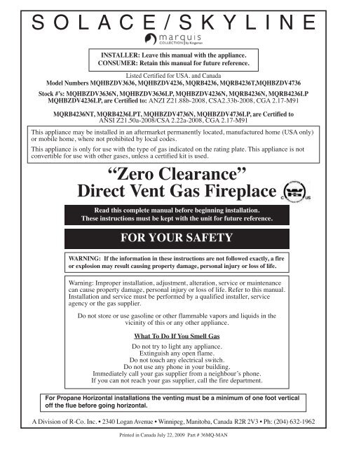
SOLACE/SKYLINEINSTALLER: Leave this manual with the appliance.CONSUMER: Retain this manual for future reference.Listed Certified for USA. and CanadaModel Numbers MQHBZDV3636, MQHBZDV4236, MQRB4236, MQRB4236T,MQHBZDV4736Stock #’s: MQHBZDV3636N, MQHBZDV3636LP, MQHBZDV4236N, MQRB4236N, MQRB4236LPMQHBZDV4236LP, are Certified to: ANZI Z21.88b-2008, CSA2.33b-2008, CGA 2.17-M91MQRB4236NT, MQRB4236LPT, MQHBZDV4736N, MQHBZDV4736LP, are Certified toANSI Z21.50a-2008/CSA 2.22a-2008, CGA 2.17-M91This appliance may be installed in an aftermarket permanently located, manufactured home (USA only)or mobile home, where not prohibited by local codes.This appliance is only for use with the type of gas indicated on the rating plate. This appliance is notconvertible for use with other gases, unless a certified kit is used.“Zero Clearance”Direct Vent Gas FireplaceRead this complete manual before beginning installation.These instructions must be kept with the unit for future reference.FOR YOUR SAFETYWARNING: If the information in these instructions are not followed exactly, a fireor explosion may result causing property damage, personal injury or loss of life.Warning: Improper installation, adjustment, alteration, service or maintenancecan cause property damage, personal injury or loss of life. Refer to this manual.Installation and service must be performed by a qualified installer, serviceagency or the gas supplier.Do not store or use gasoline or other flammable vapors and liquids in thevicinity of this or any other appliance.What To Do If You Smell GasDo not try to light any appliance.Extinguish any open flame.Do not touch any electrical switch.Do not use any phone in your building.Immediately call your gas supplier from a neighbour’s phone.If you can not reach your gas supplier, call the fire department.For Propane Horizontal installations the venting must be a minimum of one foot verticaloff the flue before going horizontal.A Division of R-Co. Inc. • 2340 Logan Avenue • Winnipeg, Manitoba, Canada R2R 2V3 • Ph: (204) 632-1962Printed in Canada July 22, 2009 Part # 36MQ-MAN
PRE-INSTALLATION QUESTIONS and ANSWERSWhy does my fireplace or stove give off odour?It is normal for your fireplace to give off some odour. This is due to the curing of the paint, adhesives,silicones and any undetected oil from the manufacturing process as well as the finishing materials usedwith the installations (e.g. marble, tile and the adhesives used to adhere this product to the walls canreact with heat and cause odours).It is recommended that you burn your gas fireplace or stove for a minimum of four hours at a time withthe fan off after the curing of the paint has been completed. These odours can last upward to 40 hoursof burn time, keep burning at a minimum of four hours per use until odours dissipate.About curing of the paintYour stove or fireplace has been painted with the highest quality silicone stove paint. This paint driesquickly in 15-20 minutes when first applied at the factory. However, due to the high temperature siliconecomponents, the paint will cure when heat is applied to the appliance as it is first used.The following information applies to the curing process to get the paint fully hard and durable.Fire the appliance four successive times for 10 minutes each firing and a 5 minute cool down betweeneach. Be aware during log and firebox paint curing that a white deposit may be developing on theinside of the glass doors. It is important to remove this white deposit from the glass doors with anappropriate cleaner to prevent build-up (such as Windex or a commercial fireplace glass cleaner).• Babies, small children, pregnant women and pets should leave the area during the cure phase.• Ventilate well, open doors and windows.• Do not touch during curing.Noise coming from the fireplace?• Noise caused by metal expanding and contracting as it heats up and cools down, similar to thesound produced by a furnace or heating duct. This noise does not affect the operation or longevityof your fireplace.• Different types and thicknesses of steel will expand and contract at different rates resulting in“cracking” and “ticking” sounds throughout the heating and cooling periods.• You should also be aware that as temperatures change within the unit these sounds will likely reoccur.Again this is normal for steel fireboxes, and is not a defect.Cleaning the GlassDuring the first few fires, a white film may develop on the glass front, as part of the curing process.The glass should be cleaned after the unit has cooled down or the film can bake on and become verydifficult to remove. Use a non-abrasive cleaner and do not attempt to clean the glass while it is hot.2
Table of ContentsMobile Home/Manufactured Housing Installation . . . . . . . . . . . . . . . . .4Installation and operation . . . . . . . . . . . . . . . . . . . . . . . . . . . . . . . . . . . .5Installation Requirements for the Commonwealth of Massachusetts . . .6MQHBZDV3636Locating your appliance . . . . . . . . . . . . . . . . . . . . . . . . . . . . . . . . . . .7Fireplace Dimensions . . . . . . . . . . . . . . . . . . . . . . . . . . . . . . . . . . . . .7Framing your gas fireplace . . . . . . . . . . . . . . . . . . . . . . . . . . . . . . . . .8Framing & Facing Requirements . . . . . . . . . . . . . . . . . . . . . . . . . . . .9Installing Clean View Kit (CVCK) . . . . . . . . . . . . . . . . . . . . . . . . .10Clearances to Combustibles . . . . . . . . . . . . . . . . . . . . . . . . . . . . . . .10Parts List . . . . . . . . . . . . . . . . . . . . . . . . . . . . . . . . . . . . . . . . . . . . . .11<strong>Kingsman</strong> Fireplace Venting . . . . . . . . . . . . . . . . . . . . . . . . . . . . . .12MQHBZDV4236/MQRB4236Locating you appliance . . . . . . . . . . . . . . . . . . . . . . . . . . . . . . . . . . .13Fireplace Dimensions . . . . . . . . . . . . . . . . . . . . . . . . . . . . . . . . . . . .13Framing your gas fireplace . . . . . . . . . . . . . . . . . . . . . . . . . . . . . . . .14Framing & Facing Requirements . . . . . . . . . . . . . . . . . . . . . . . . . . .15Installing Clean View Kit (CVCK) . . . . . . . . . . . . . . . . . . . . . . . . .16Clearances to Combustibles . . . . . . . . . . . . . . . . . . . . . . . . . . . . . . .16Parts List . . . . . . . . . . . . . . . . . . . . . . . . . . . . . . . . . . . . . . . . . . . . . .17<strong>Kingsman</strong> Fireplace Venting . . . . . . . . . . . . . . . . . . . . . . . . . . . . . .18MQHBZDV4736Locating you appliance . . . . . . . . . . . . . . . . . . . . . . . . . . . . . . . . . . .19Fireplace Dimensions . . . . . . . . . . . . . . . . . . . . . . . . . . . . . . . . . . . .19Framing your gas fireplace . . . . . . . . . . . . . . . . . . . . . . . . . . . . . . . .20Framing & Facing Requirements . . . . . . . . . . . . . . . . . . . . . . . . . . .21Installing Clean View Kit (CVCK) . . . . . . . . . . . . . . . . . . . . . . . . .22Clearances to Combustibles . . . . . . . . . . . . . . . . . . . . . . . . . . . . . . .22Parts List . . . . . . . . . . . . . . . . . . . . . . . . . . . . . . . . . . . . . . . . . . . . . .23<strong>Kingsman</strong> Fireplace Venting . . . . . . . . . . . . . . . . . . . . . . . . . . . . . .24Clearance, Mantels & Surrounds . . . . . . . . . . . . . . . . . . . . . . . . . . .25-26Dimensions & Installation of Wall Mount Surrounds . . . . . . . . . . . . . .27Fan Installation - MQHBZDV3636/4236/4736 . . . . . . . . . . . . . . . . . .28Installing MQRB4236 Liner Panels . . . . . . . . . . . . . . . . . . . . . . . . . . .29Brick Installation - MQHBZDV3636/4236/4736 . . . . . . . . . . . . . . . . .30Installation of HB Porcelain Liners . . . . . . . . . . . . . . . . . . . . . . . . . . . .31Gas Line Installation . . . . . . . . . . . . . . . . . . . . . . . . . . . . . . . . . . . . . . .32Millivolt system, lighting, & burner control . . . . . . . . . . . . . . . . . . . . .33Trouble shooting the gas control system . . . . . . . . . . . . . . . . . . . . . . . .34Burner System Removal - MQHBZDV3636/4236/4736 . . . . . . . . . . .35Gas Conversion - MQHBZDV3636/4236/4736 & MQRB4236 . . . . . .36Installation of Gas Conversion Kit . . . . . . . . . . . . . . . . . . . . . . . . . . . .37Door and glass information . . . . . . . . . . . . . . . . . . . . . . . . . . . . . . . . . .38Log Placement Guide . . . . . . . . . . . . . . . . . . . . . . . . . . . . . . . . . . . . . .39Rock F2 Setup . . . . . . . . . . . . . . . . . . . . . . . . . . . . . . . . . . . . . . . . .40-41Rock F1 Setup . . . . . . . . . . . . . . . . . . . . . . . . . . . . . . . . . . . . . . . . .42-43Accessories for MQRB3328/3632/4236 . . . . . . . . . . . . . . . . . . . . . . . .44Vent termination . . . . . . . . . . . . . . . . . . . . . . . . . . . . . . . . . . . . . . . . . .45General vent installation information . . . . . . . . . . . . . . . . . . . . . . . . . .46Venting graph . . . . . . . . . . . . . . . . . . . . . . . . . . . . . . . . . . . . . . . . . . . . .47Installation of side wall venting- MQHBZDV36363/4236/4736 . . . . . . . . . . . . . . . . . . . . . . . . . . .48Vertical Venting . . . . . . . . . . . . . . . . . . . . . . . . . . . . . . . . . . . . . . . . . . .49Limited Lifetime Warranty . . . . . . . . . . . . . . . . . . . . . . . . . . . . . . . . . .50
Mobile Home/Manufactured Housing InstallationThis Direct Vent System Appliance must be installed in accordance with the manufacturer’s installation instructions and theManufactured Home Construction and Safety Standard Title 24 CFR, Part 3280, or the current Standard for Fire Safety Criteria forManufactured Home Installations, Sites, and Communities ANSI/NFPA 501A, and with CAN/CSA Z240 MH Mobile Home Standardin Canada.THE MQHBZDV3636N, MQHBZDV3636LP, MQHBZDV4236N and MQHBZDV4236LP MAY BE INSTALLED IN MANU-FACTURED (MOBILE) HOMES AFTER FIRST SALE IN THE USA. IN CANADA THE MQHBZDV3636N, MQH-BZDV3636LP, MQHBZDV4236N and MQHBZDV4236LP MAY BE INSTALLED IN MANUFACTURED (MOBILE)HOMES.Please follow the current ANSI/NFPA 70 National Electrical Code in the USA and CAN/CSA C22.1 Canadian National Electrical Codein Canada.An appliance must be grounded to the steel chassis of the home with 8 ga. copper wire using a serrated or star washer to penetrate paintor protective coating to insure grounding.Use carriage bolt at the attachment point (see diagram above) to secure the appliance to the floor.Warning: Do not compromise the structural integrity of the manufactured home wall, floor or ceiling, duringinstallation of appliance or venting.For required venting components see venting installation in appropriate section of this manual.Certified for installation in a bedroom or bed/sitting room. In Canada must be installed with listed milli volt thermostat. In USAsee local codes.4
Installation and OperationInstallation RegulationsThis gas appliance must be installed by a qualified installerin accordance with local building codes, or in the absence oflocal codes, with the current CAN/CGA-B149.1 or .2Installation Code (in Canada) or the current National FuelGas Code Z223.1 when installed in the United States.This appliance, when installed, must be electrically connectedand grounded in accordance with local codes, or in theabsence of local codes, with the current CSA C22.1Canadian Electrical Code or with the national ElectricalCode; ANSI/NFPA 70-1987 when installed in the UnitedStates.Vertical Venting in Cold ClimatesIn cold climate conditions where temperatures gobelow -10 degrees Celsius or 14 degreesFahrenheit, we recommend that the chase be insulatedand where the vent pipe enters into the atticspace that the pipe be wrapped with an insulatedmylar sleeve. This will increase the temperature ofthe vent and help the appliance to vent properly incold weather conditions.It is also important in vertical vented direct ventappliances that the appliance be operated daily duringthe winter months as this will help stop theTermination from freezing up. We recommendusing a thermostat set at room temperature to allowthe unit to cycle.FOR SAFE INSTALLATION AND OPERATION OFYOUR GAS FIREPLACE PLEASE NOTE THE FOL-LOWING:1. This appliance gives off high temperatures and should belocated out of heavy traffic areas and away from furnitureand draperies.2. Children and adults should be alerted to the hazards ofthe high surface temperatures of this appliance andshould stay away to avoid burns or ignition of clothing.3. Children should be carefully supervised when they are inthe same room as your fireplace appliance.NOTE: It is recommended that a Carbon Monoxide (CO)Detector be installed in or near bedrooms and on all levelsof your home. Place a detector about 15 feet (4.5 meters)outside the room that houses your gas appliance.Warning: When purging the gas line, the glass front must beremoved.Never use your gas fireplace as a cooking device.The Burner/Log Assembly has been engineered and permanentlyadjusted for proper flame control.Do not alter gas orifice.54. Under no circumstances should this appliance be modified.Any parts that have to be removed for servicingshould be replaced prior to operating this appliance.5. Installation and repair should be done by a qualified serviceperson. The appliance should be inspected beforeuse and at least annually by a professional service person.More frequent cleaning may be required due toexcessive lint from carpeting, bedding material, etcetera.It is imperative that control compartments, burners andcirculating air passageways of the appliance be keptclean.6. Control compartments, burners and air passages in thisappliance should be kept clean and free of dust and lint.Make sure that the gas valve and pilot light are turned offbefore you attempt to clean this unit.7. The venting system (chimney) of this appliance shouldbe inspected at least once a year and if needed, your ventingsystem should be cleaned.8. Clothing or other flammable material should not beplaced on or near the appliance. This appliance shouldnot be used as a drying rack for clothing nor shouldChristmas stockings or decorations be hung from it.9. Under no circumstances should any solid fuels (wood,paper) be used in this appliance.10. For safe operation, glass doors must be closed.11. Do not use this heater if any part has been under water.Immediately call a qualified service technician to inspectthe heater and to replace any part of the control systemand any gas control which has been under water.12. WARNING: Do not operate appliance with the glassfront removed, cracked or broken. Replacement of glassshould be done by a licensed or qualified service person.13. Do not operate appliance unless completely installed asper installation instructions.14. In the Commonwealth of Massachusetts a CO detectormust be installed in the same room as the appliance.15. Gas fired appliances may be used only for supplementalheat and/or decorative purposes and under no circumstancesshall they provide a primary heat source.Periodically remove the logs from the grate assembly andvacuum any loose particles from the grate and burner areas.See log/rock placement on pages 39-44 to remove logs, vacuumburner parts and replace logs.Note: It is normal for your gas fireplace to give off someodor the first time it is burned. This is due to the curing ofthe paint and any undetected oil from the manufacturingprocess.Please ensure that your room is well ventilated - open allwindows. It is recommended that you burn your gas fireplacefor at least four (4) hours the first time you use itwithout the fan on.Make adequate accessibility clearances for servicing andproper operation.This appliance must not be connected to a chimney flue servinga separate solid fuel burning appliance.Be sure that the flow of combustion and ventilation air is notobstructed.
Installation Requirements for the Commonwealth of MassachusettsIn the Commonwealth of Massachusetts, the installer or service agent shall be a plumber or gas fitter licensed by theCommonwealth.When installed in the Commonwealth of Massachusetts or where applicable codes; the unit shall be installed with a CO detectorper the requirements listed below.1. For direct-vent appliances, mechanical-vent heating appliances or domestic hot water equipment, where the bottom of thevent terminal and the air intake is installed below four feet above grade the following requirements must be satisfied:A If there is not one already present, on each floor level where there are bedroom(s), a carbon monoxide detector and alarm shallbe placed in the living area outside the bedroom(s). The carbon monoxide detector shall comply with NFPA 720 (2005 Edition).B. A carbon monoxide detector shall be located in the room that houses the appliance or equipment and shall:a. Be powered by the same electrical circuit as the appliance or equipment such that only one service switch services both theappliance and the carbon monoxide detector;b. Have battery back-up power;c. Meet ANSI./UL 2034 Standards and comply with NFPA 720 (2005 Edition); andd. Have been approved and listed by a Nationally Recognized Testing Laboratory as recognized under 527 CMR.C. A Product-approved vent terminal must be used, and if applicable, a Product-approved air intake must be used. Installation shallbe in strict compliance with the manufacturer’s instructions. A copy of the installation instructions shall remain with the applianceor equipment at the completion of the installation.D. A metal or plastic identification plate shall be mounted at the exterior of the building, four feet directly above the location of ventterminal. The plate shall be of sufficient size to be easily read from a distance of eight feet away, and read “Gas Vent DirectlyBelow”.2. For direct-vent appliances, mechanical-vent heating appliances or domestic hot water equipment where the bottom of the vent terminaland the air intake is installed above four feet above grade the following requirements must be satisfied:A If there is not one already present, on each floor level where there are bedroom(s), a carbon monoxide detector and alarm shallbe placed in the living area outside the bedroom(s). The carbon monoxide detector shall comply with NFPA 720 (2005 Edition).B. A carbon monoxide detector shall:a. Be located in the room that houses the appliance or equipment;b. Be either hard-wired or battery powered or both; andc. Shall comply with NFPA 720 (2005 Edition).C. A Product-approved vent terminal must be used, and if applicable, a Product-approved air intake must be used. Installation shallbe in strict compliance with the manufacturer instructions. A copy of the installation instructions shall remain with the applianceor equipment at the completion of the installation.6
MQHBZDV3636 - Locating your ApplianceInstalling with Top VentA - Flat on a wallB - Across the cornerC - As an islandD - As a room dividerE - Flat on wall cornerF - Exterior wallIsland installation with a top vent is possible as long as the horizontalportion of the vent system does not exceed 20 feet (6.1 m).MQHBZDV36 louveredFireplace DimensionsMQHBZDV36 with HB36CVCK(Clean View Circulating Kit)7
MQHBZDV3636 - Framing for your Gas FireplaceFraming Specifications1. Cold climate installation recommendation: When installing this fireplaceagainst non insulated exterior wall or chase, it is recom -mended that the outer walls be insulated to conform to applicableinsulation codes. Drywall must be installed over insulation toprevent contact of insulation and unit.2. Choose fireplace location and frame in accordance with the fireplaceframing dimensions specified (See Framing Diagrams). Bendnailing tabs forward on left and right of unit and place fireplace intoframed enclosure. This allows for 1/2” in front of framing tabs forfinishing materials.3. Drywall or other material can extend flush with the appliance on thebottom, sides and top of fireplace. (louvered models only)4. When installing horizontal with a 90 degree bend maintain a minimumof two and a half (2.5”) inches above the bend in enclosures.5. For a fireplace with louvers combustible floor can raise 1”above the bottom of the fireplace. For a fireplace withHB36CVCK (Clean view Circulating Kit) floor or hearth canraise 7” above the bottom of the fireplace with portionsbeing combustible and non combustible. See drawing on followingpage.6. When installing MQHB36SW surround,the fireplace must beraised a minimum of 3 1/2” above the finished floors, toaccommodate the wall surround. The fireplace may be raisedhigher but the 60” clearance measured from the bottom ofthe fireplace to the ceiling must be maintained at all times.(i.e. For an 8 ft. ceiling the unit can be raised only 36 inches.)For Propane Horizontal Installations the venting must be a minimum of one foot vertical off the flue before the elbow on anyhorizontal runs of one foot or greater. This allows for cleaner combustion and greatly reduces carboning and cleaning of glass.MQHBZDV36 LouveredMQHBZDV36 WITH HB36CVCK(CLEAN VIEW CIRCULATING KIT)8
MQHBZDV3636 - Framing and Facing RequirementsHBZDV36 WITH HB36CVCK (CLEAN VIEW CIRCULATING KIT)HB36CVCK WITH MQHB36SW SURROUND9
MQHBZDV3636 - HOW TO INSTALL CLEAN VIEW KIT (CVCK)CAUTION: When using CVCK DO NOT INSTALL a Louver assembly1. Install optional Fan Kit (See Fan Instruction)2. Fold two standoffs up into position & mount with supplied Screws. (Fig. 1)3. Hang CVCK on top of fireplace retainer tabs and rotate down into position. (Fig. 2)4. Using the screws provided, fasten the non-combustible header onto the top of the CVCK assembly.5. Using four supplied #6 screws, fasten CVCK kit to the inside frame of unit6. Kit is supplied with 2 valve extension knobs. Align the notches and slide the extensions onto the valve knobs.7. DO NOT brick or tile beyond the inside area of the CVCK kit to allow for removal of door.8. Install optional pull screen system: First slide curtain onto rods and slide round end of rod into side post Ref: A, using 1/2” DT screws, mount theflattened end of rod to the bottom side of the rod hanger bracket (Ref: B). Repeat this step for the opposite side.Clearance to CombustiblesBack (from Standoffs)Side (from standoffs)FloorCeiling (from bottom of fireplace)Top (from standoffs)Top of 90 degree bend in MinimumEnclosure of 42 to 43 inchesTop of 90 degree bend inEnclosure over 43 inchesTop of Horizontal PipeSide & Bottom of Horizontal PipeVertical Vent PipeVertical Vent PipeMQHBZDV3636 - Clearance to Combustibles0 inches/0 mm0 inches/0 mm0 inches/0 mm60 inches/150 cm0 inches/0 mm3 1/2 inches/89 mm / All Vent Systems2 1/2 inches/64 mm / All Vent Systems1 1/2 inches/38 mm / All Vent Systems1 inch/25.5mm / All Vent Systems1 inch/25.5mm / <strong>Kingsman</strong> Vent Systems1 1/4 inch/32mm / Simpson/AmeriVent/Selkirk Direct TempSystems10Note: Additional Access forgasline installation andFan Electrical installation!When CVCK kit isinstalled in framingremove 2 screws from theright and left side of bottompanel Ref: C. Oncescrews are removed, bottompanel can be rotatedforward for access to gasvalve and fan system.(NOTE -Floor) if installing theappliance directly on carpeting orother combustible materials otherthan wood flooring, the applianceshall be installed on a metal orwood panel, the full width anddepth of the appliance. Carpetmay extend 1 inch above thefloor of appliance.For units with CVCK (ClearView Circulating Kit) seeframing with CVCK to establishfloor heights
OverlaysMQHBZDV3636 Parts ListHB36ADTH Arch Door Frame - Top Half BlackFireplace Part NumbersHB36ADDX Arch Door Frame - Deluxe BlackMQHBZDV3636N Fireplace Heater Rated NG, Ceramic Glass,30,500 BTU AT 75% efficient. Approved forHB36ADDA Arch Door Frame - Double Arch Blackbedroom and mobile home.HB36ADDD Arch Door Frame - Double Door Arch BlackMQHBZDV3636LP Fireplace Heater Rated LP, Ceramic Glass, Accessories29,200 BTU AT 75% efficient. Approved for Z36FK Fan Kit w/Variable Speed Wall Mount Controlbedroom and mobile home.(Temperature Sensing)FIREPLACE REQUIREMENTSZ1MT Thermostat Millivolt Wall MountGrills or CVCK (clean view circulating kit)(Required Z80PT Thermostat Programmable Digital Millivoltfor each unit)Wall Mount (1F80-40)HB36CVCK CVCK(clean view circulating kit) no grill required Z1RC Remote Control Millivolt (On/Off with LED) (Model I)HB36GBA Grill Kit - Classic Builder Antique Brass ZART Remote Control Thermostat Millivolt (Model K)HB36GBC Grill Kit - Classic Builder ChromeRMCBN Remote Control - Basic - Natural GasHB36GBP Grill Kit - Classic Builder Polish Brass(On/Off, Hi/Lo Flame Adjustment)HB36GBL Grill Kit - BlackRMCBP Remote Control - Basic - Liquid PropaneHB36PBL Panel Grill Kit - Black(On/Off, Hi/Lo Flame Adjustment)LOG SETS/ROCK KITS: (Required for each unit)DCHS Remote Control HeatshieldLOGF36 Log Set - 7 pce. - /Fibre Split OakVLBIT4 Log Bits - Large Four Piece KitMQROCK1 Rock Set Tan (HBZDV/MQRB)VLBIT6 Log Bits - Small Six Piece KitMQROCK2 Rock Set Natural (HBZDV/MQRB)Refractory LinerMQROCK3 Rock Set Multi-Color (HBZDV/MQRB) HB36PL Porcelain Reflective LinerMQRSP2 Rock Platform, Support, and 4 ScrewsHB36RLC Refractory Liner Classic(MQHBZDV3636, 4236)HB36RLT Refractory Liner TraditionalFireplace Wall Mount Finishing Surrounds for HB36CVCK HB36RLH Refractory Liner Herring BoneMQHB36SWCCBL Surround Concave BlackReplacement Burner Assembly(Coverage 40 1/2” H x 49 1/2” W) 3636MQ-BNGSI Burner Assembly - Natural Gas c/w ValveMQHB36SWCCPW Surround Concave PewterSystem (MQHBZDV3636N)(Coverage 40 1/2” H x 49 1/2” W) 3636MQ-BLPSI Burner Assembly - Liquid Propane c/w ValveMQHB36SWCVBL Surround Convex BlackSystem (MQHBZDV3636LP)(Coverage 41” H x 40 1/2” W)Conversion Kit (Sit Valve Only)MQHB36SWCVPW Surround Convex Pewter3632HB-CKLP LP Conversion Kit for HBZDV3632/3636(Coverage 41” H x 40 1/2” W)3632HB-CKNG NG Conversion Kit for HBZDV3632/3636ACCESSORIESValve System Parts - New Top convertible SITFireplace Surrounds - TrimsHB36SAB Surround - Antique Brass1000-P136WR Thermopile GOAI-524(Coverage 35 1/2” H x 41 1/8” W) 1001-P069SI Electrode Sparker 915.069 TC SITHB36SBL Surround - Black1001-P216SI Thermocouple 290.216 TC SIT(Coverage 35 1/2” H x 41 1/8” W) 1001-P165SI Orifice Pilot NG 977.165 TC SITHB36SCR Surround - Chrome(Coverage 35 1/2” H x 41 1/8” W)1001-P167SI Orifice Pilot LP 977.167 TC SITHB36SPB Surround - Polish Brass1001-P633SI Valve Nova LP Hi/Lo 0820651(Coverage 35 1/2” H x 41 1/8” W) 1001-P634SI Valve Nova NG Hi/Lo 0820652HB36SLAB Surround Slim Line - Antique Brass 1001-P713SI Pilot Burner LP 199.713 TC SIT(Coverage 35 1/4” H x 37 1/2” W)1001-P714SI Pilot Burner NG 199.714 TC SITHB36SLCR Surround Slim Line - Chrome(Coverage 35 1/4” H x 37 1/2” W)HB36SLPB Surround Slim Line - Polish Brass(Coverage 35 1/4” H x 37 1/2” W)HB36SLBL Surround Slim Line - Gun Metal Black(Coverage 35 1/4” H x 37 1/2” W)Designer Doors for 36” Fireplaces - OperativeHB36DDA1BL Designer Door Arch - Series 1 - BlackHB36DDTA1A Trim - Antique for Designer Arch - Series 1HB36DDTA1C Trim - Chrome for Designer Arch - Series 1HB36DDTA1P Trim - Polish Brass for Designer Arch - Series 1HB36DDS1BL Designer Door Straight - Series 1 - BlackHB36DDTS1A Trim - Antique for Designer Straight - Series 1HB36DDTS1C Trim - Chrome for Designer Straight - Series 1HB36DDTS1P Trim - Polish for Designer Straight - Series 1Child Safety ScreensHB36CSSHB36PSKMiscellaneous Parts1000-150GE #Silicone GE Red IS806 #7361000-150MP #Hi-Temp Millpac Sealant 8400991000-214 #Piezo-Igniter 1244-17 MARK 211000-215 #Pal Nut (18MMXI.5MM)BLK (1364.03)1000-218 #Switch Ivory (1451/001)1000-227 #Cover Ivory (86001/001)1000-255 #Orifice Brass - (State Size)1000-EMBER #Moon Rock2000-080 #Thermodisc 2450 (For Blower)2000-081 #Blower Motor QLN65/24001000-085 #Control Variable Speed KBWC-13BV1000-306 Thermalcord - Adhesive Back for Door Frame36HB-310 Ceramic Glass - For All HBZDV3600Child Safety Screen - 36” HBZDV Fireplaces 36HB-123 Upper Door SpringPull Screen Kit for CVCK11
<strong>Kingsman</strong> Fireplace VentingCatalogNumber DescriptionZDVHSK Horizontal Vent Starter Kit - 3 FT LengthHorizontal Vent Termination, Wall Thimble,36” Flex Pipe, Mill Pac, screws/washers, springs.ZDVHSK5 Horizontal Vent Starter Kit - 5 FT LengthHorizontal Vent Termination, Wall Thimble,60” Flex Pipe, Mill Pac, screws/washers, springs.FDVVT40 Vertical Vent Termination converts from15’-40’ to under 15’FDVHT Horizontal Vent TerminationFDVHSQ Horizontal Square TerminationZDVST Horizontal Snorkel Termination(34” Tall, 24” Center to Center)FDVHSCU Safety Cage for Horizontal TerminationZDVAIS Attic Insulation ShieldZDVVOS Offset SupportZDVFS Firestop SpacerZDVRS Roof SupportZDVWT Wall Thimble (Horizontal Venting)ZDVSSLR Siding Shield - Large ReturnZDV48GP Galvanized Pipe 7” Dia. x 48” (VerticalInstallations)ZDVAAF Flashing 7” c/w Storm Collar (1/12 to 7/12)ZDVAF2 Flashing 7” c/w Storm Collar (8/12 to 12/12)ZDVAF3 Flashing 7” c/w Storm Collar FlatZDV7SC Storm Collar 7”ZDVFK5 Flex Kit (4” & 7” Dia.) x 2.5’ (Unexpanded) 5’ExpandedZDVFK8 Flex Kit (4” & 7” Dia.) x 4’ (Unexpanded) 8’ExpandedZDVFK20 Flex Kit (4” & 7” Dia.) x 10’ (Unexpanded) 20’Expanded*Kits are complete with spring stand-offs, silicone.ZDV4FC Flex Connector 4” DiameterZDV7FC Flex Connector 7” DiameterZDV4SSZDVDFASpring 4” Standoff SpacerSimpson Dura-Vent Fireplace Adapter(for ZDV33/36/42/47, ZDV6000, MDV31 &HB models)ZDVHSKSQKit -ZDVHSKSQ5Kit -FDVHSQHorizontal Square Termination Vent Starter3 FT LengthHorizontal Vent Termination, Wall Thimble,Wall Thimble, 36” Flex Pipe, Mill PacHorizontal Square Termination Vent Starter5 FT LengthHorizontal Vent Termination, Wall Thimble,Wall Thimble, 60” Flex Pipe, Mill PacHorizontal Square Vent Termination12
MQHBZDV4236/MQRB4236 - Locating your ApplianceInstalling with Top VentA - Flat on a wallB - Across the cornerC - As an islandD - As a room dividerE - Flat on wall cornerF - Exterior wallIsland installation with a top vent is possible as long as thehorizontal portion of the vent system does not exceed 20 feet(6.1 m).MQHBZDV42/MQRB4236 louveredFireplace DimensionsMQHBZDV42/MQRB4236 with HB42CVCK(Clean View Circulating Kit)13
MQHBZDV4236/MQRB4236 - Framing for your Gas FireplaceFraming Specifications1. Cold climate installation recommendation: When installing this fireplaceagainst non insulated exterior wall or chase, it is recom mendedthat the outer walls be insulated to conform to applicable insulationcodes. Drywall must be installed over insulation to prevent contact ofinsulation and unit.2. Choose fireplace location and frame in accordance with the fireplaceframing dimensions specified (See Framing Diagrams). Bend nailingtabs forward on left and right of unit and place fireplace into framedenclosure. This allows for 1/2” in front of framing tabs for finishingmaterials.3. Drywall or other material can extend flush with the appliance on thebottom, sides and top of fireplace. (louvered models only)4. When installing horizontal with a 90 degree bend maintain a minimumof two and a half (2.5”) inches above the bend in enclosures.5. For a fireplace with louvers combustible floor can raise 1”above the bottom of the fireplace. For a fireplace withHB42CVCK (Clean view Circulating Kit) floor or hearth canraise 7” above the bottom of the fireplace with portions beingcombustible and non combustible. See drawing on followingpage.6. When installing MQHB42SW surround,the fireplace must beraised a minimum of 3 1/2” above the finished floors, toaccommodate the wall surround. The fireplace may be raisedhigher but the 60” clearance measured from the bottom of thefireplace to the ceiling must be maintained at all times. (i.e.For an 8 ft. ceiling the unit can be raised only 36 inches.)It is recommended for Propane Horizontal Installations that the venting should be a minimum of one foot vertical off the fluebefore the elbow on any horizontal runs of one foot or greater. This allows for cleaner combustion and greatly reduces carboningand cleaning of glass. (Does not apply to Back Flue Models).MQHBZDV42/MQRB4236 louveredMQHBZDV42/MQRB4236 WITH HB42CVCK(CLEAN VIEW CIRCULATING KIT)14
MQHBZDV4236/MQRB4236 - Framing and Facing RequirementsHBZDV42 WITH HB42CVCK (CLEAN VIEW CIRCULATING KIT)HB42CVCK WITH MQHB42SW SURROUND*Note: A HBCVCK must be used when installing a MQHBSW Wall Surround.15
MQHBZDV4236/MQRB4236 - HOW TO INSTALL CLEAN VIEW KIT (CVCK)CAUTION: When using CVCK DO NOT INSTALL a Louver assembly1. Install optional Fan Kit (See Fan Instruction)2. Fold two standoffs up into position & mount with supplied Screws. (Fig. 1)3. Hang CVCK on top of fireplace retainer tabs and rotate down into position. (Fig. 2)4. Using the screws provided, fasten the non-combustible header onto the top of the CVCK assembly.5. Using four supplied #6 screws, fasten CVCK kit to the inside frame of unit6. Kit is supplied with 2 valve extension knobs. Align the notches and slide the extensions onto the valve knobs.7. DO NOT brick or tile beyond the inside area of the CVCK kit to allow for removal of door.8. Install optional pull screen system: First slide curtain onto rods and slide round end of rod into side post Ref: A, using 1/2” DT screws, mount theflattened end of rod to the bottom side of the rod hanger bracket (Ref: B). Repeat this step for the opposite side.MQHBZDV 4236 - Clearance to CombustiblesClearance to CombustiblesBack (from Standoffs)0 inches/0 mmSide (from standoffs)0 inches/0 mmFloor0 inches/0 mmCeiling (from bottom of fireplace) 60 inches/150 cmTop (from standoffs)0 inches/0 mmTop of 90 degree bend in MinimumEnclosure of 45 to 46 inches 5 inches/128 mm / All Vent SystemsTop of 90 degree bend inEnclosure over 46 inches 2 1/2 inches/64 mm / All Vent SystemsTop of Horizontal Pipe1 1/2 inches/38 mm / All Vent SystemsSide & Bottom of Horizontal Pipe 1 inch/25.5mm / All Vent SystemsVertical Vent Pipe1 inch/25.5mm / <strong>Kingsman</strong> Vent SystemsVertical Vent Pipe1 1/4 inch/32mm / Simpson/AmeriVent/Selkirk Direct TempSystems16Note: Additional Access forgasline installation andFan Electrical installation!When CVCK kit isinstalled in framingremove 2 screws from theright and left side of bottompanel Ref: C. Oncescrews are removed, bottompanel can be rotatedforward for access to gasvalve and fan system.(NOTE -Floor) if installing theappliance directly on carpetingor other combustible materialsother than wood flooring, theappliance shall be installed ona metal or wood panel, the fullwidth and depth of theappliance. Carpet may extend1 inch above the floor ofappliance.For units with CVCK (ClearView Circulating Kit) seeframing with CVCK toestablish floor heights
MQHBZDV4236/MQRB4236 - Parts ListFireplace Part NumbersMQHBZDV4236N Fireplace Heater Rated NB, Ceramic Glass30,500 BTU at 75% efficient.MQHBZDV4236LP Fireplace Heater Rated LP, Ceramic Glass29,200 BTU at 75% efficient.MQRB4236NT Fireplace Decorative, Tempered, MillivoltNatural Gas, 24,000 BTUMQRB4236LPT Fireplace Decorative, Tempered, MillivoltPropane, 24,000 BTUMQRB4236N Fireplace Heater Rated Ceramic, MillivoltNatural Gas, 30,500 BTUMQRB4236LP Fireplace Heater Rated Ceramic, MillivoltPropane, 30,000 BTUFIREPLACE REQUIREMENTSGrills or CVCK (clean view circulating kit)(Requiredfor each unit)HB42CVCK CVCK(clean view circulating kit) no grill requiredHB42GBA Grill Kit - Classic Builder Antique BrassHB42GBC Grill Kit - Classic Builder ChromeHB42GBP Grill Kit - Classic Builder Polish BrassHB42GBL Grill Kit - BlackHB42PBL Panel Grill Kit - BlackLOG SETS/ROCK/GLASS KITS: (Required for each unit)LOGF36 Log Set - 7 pce. - Fibre SplitMQROCK1 Rock Set Tan (HBZDV/MQRB)MQROCK2 Rock Set Natural (HBZDV/MQRB)MQROCK3 Rock Set Multi-Color (HBZDV/MQRB)MQRSP2 Rock Platform, Support and 4 Screws(MQHBZDV3636, MQHBZDV4236)MQEMBER Glowing Embers, 2 ea. (MQRB4236)optionalMQRBD1 Driftwood/Rocks, 4 ea. (MQRB4236)optionalMQG10W Decorative Glass 1/2” <strong>White</strong> 10 lbsMQG10B Decorative Glass 1/4” Black 10 lbsFireplace Wall Mount Finishing Surround forHB42CVCK KitsMQHB42SWCCBLSurround Concave Black(Coverage 42 3/4” H x 55 7/16” W)MQHB42SWCCPW Surround Concave Pewter(Coverage 42 3/4” H x 55 7/16” W)MQHB42SWCVBL Surround Convex Black(Coverage 42 15/16” H x 44 5/16” W)MQHB42SWCVPW Surround Convex Pewter(Coverage 42 15/16” H x 44 5/16” W)ACCESSORIESFireplace Surrounds - TrimsHB42SAB Surround - Antique Brass(Coverage 37 5/8” H x 45 1/8” W)HB42SBL Surround - Black(Coverage 37 5/8” H x 45 1/8” W)HB42SCR Surround - Chrome(Coverage 37 5/8” H x 45 1/8” W)HB42SPB Surround - Polish Brass(Coverage 37 5/8” H x 45 1/8” W)HB42SLAB Surround Slim Line - Antique Brass(Coverage 37 3/8” H x 43 3/8” W)HB42SLCR Surround Slim Line - Chrome(Coverage 37 3/8” H x 43 3/8” W)HB42SLPB Surround Slim Line - Polish Brass(Coverage 37 3/8” H x 43 3/8” W)HB42SLBL Surround Slim Line - Gun Metal Black(Coverage 37 3/8” H x 43 3/8” W)Designer Doors for 42” Fireplaces - OperativeHB42DDA1BL Designer Door Arch - Series 1 - BlackHB42DDTA1A Trim - Antique for Designer Arch - Series 1HB42DDTA1C Trim - Chrome for Designer Arch - Series 1HB42DDTA1P Trim - Polish Brass for Designer Arch - Series 1HB42DDS1BL Designer Door Straight - Series 1 - BlackHB42DDTS1A Trim - Antique for Designer Straight - Series 1HB42DDTS1C Trim - Chrome for Designer Straight - Series 1HB42DDTS1P Trim - Polish for Designer Straight - Series 1Child Safety ScreensHB42CSS Child Safety Screen - 42” HBZDV FireplacesHB42PSK Pull Screen Kit for CVCKOverlaysHB42ADTH Arch Door Frame - Top Half BlackHB42ADDX Arch Door Frame - Deluxe BlackHB42ADDA Arch Door Frame - Double Arch BlackHB42ADDD Arch Door Frame - Double Door Arch BlackAccessoriesZ36FK Fan Kit w/Variable Speed Wall Mount Control(Temperature Sensing)Z1MT Thermostat Millivolt Wall MountZ80PT Thermostat Programmable Digital MillivoltWall Mount (1F80-40)Z1RC Remote Control Millivolt (On/Off with LED) (Model I)ZART Remote Control Thermostat Millivolt (Model K)RMCBN Remote Control - Basic - Natural Gas(On/Off, Hi/Lo Flame Adjustment)RMCBP Remote Control - Basic - Liquid Propane(On/Off, Hi/Lo Flame Adjustment)DCHS Remote Control HeatshieldVLBIT4 Log Bits - Large Four Piece KitVLBIT6 Log Bits - Small Six Piece KitRefractory LinerHB42PL Porcelain Reflective Liner (all HB42 models)MQRB42PB Porcelain Bottom for MQRB4236HB42RLC Refractory Liner Classic (all HB42 models)MQRB42PL Porcelain Liner (3 pce.) for MQRB4236HB42RLT Refractory Liner Traditional (all HB42 models)HB42RLH Refractory Liner Herring Bone (all HB42 models)Replacement Burner Assembly4236MQ-BNGSI Burner Assembly - Natural Gas c/w Valve System(MQHBZDV4236N)4236RB-BNGSI Burner Assembly - Natural Gas c/w ValveSystem (MQRB4236)4236MQ-BLPSI Burner Assembly - Liquid Propane c/w ValveSystem (MQHBZDV4236LP)4236RB-BLPSI Burner Assembly - Liquid Propane c/w ValveSystem (MQRB4236)4236RBT-BNGSI Burner Assembly - Natural Gas c/w ValveSystem (MQRB4236NT)4236RBT-BLPSI Burner Assembly - Liquid Propane c/w ValveSystem (MQRB4236LPT)Conversion Kit (Sit Valve Only)4232HB-CKLP LP Conversion Kit for MQHBZDV42364232HB-CKNG NG Conversion Kit for MQHBZDV42364236RB-CKNG NG Conversion Kit for MQRB42364236RB-CKLP LP Conversion Kit for MQRB42364236RBT-CKNG NG Conversion Kit for MQRB4236T4236RBT-CKLP LP Conversion Kit for MQRB4236TValve System Parts - New Top convertible SIT1000-P136WR Thermopile GOAI-5241001-P069SI Electrode Sparker 915.069 TC SIT1001-P216SI Thermocouple 290.216 TC SIT1001-P165SI Orifice Pilot NG 977.165 TC SIT1001-P167SI Orifice Pilot LP 977.167 TC SIT1001-P633SI Valve Nova LP Hi/Lo 08206511001-P634SI Valve Nova NG Hi/Lo 08206521001-P713SI Pilot Burner LP 199.713 TC SIT1001-P714SI17Pilot Burner NG 199.714 TC SIT
CatalogNumber DescriptionMiscellaneous Parts1000-150GE #Silicone GE Red IS806 #7361000-150MP #Hi-Temp Mill Pac Sealant 8400991000-214 #Piezo-Igniter 1244-17 MARK 211000-215 #Pal Nut (18MMXI.5MM)BLK (1364.03)1000-218 #Switch Ivory (1451/001)1000-227 #Cover Ivory (86001/001)1000-255 #Orifice Brass - (State Size)1000-EMBER #Moon Rock2000-080 #Thermodisc 2450 (For Blower)2000-081 #Blower Motor QLN65/24001000-085 #Control Variable Speed KBWC-13BV1000-306 Thermalcord - Adhesive Back for Door Frame42HB-310 Ceramic Glass36HB-123 Upper Door SpringZDVHSK Horizontal Vent Starter Kit - 3 FT LengthHorizontal Vent Termination, Wall Thimble,36” Flex Pipe, Mill Pac, screws/washers, springs.ZDVHSK5 Horizontal Vent Starter Kit - 5 FT LengthHorizontal Vent Termination, Wall Thimble,60” Flex Pipe, Mill Pac, screws/washers, springs.FDVVT40 Vertical Vent Termination converts from15’-40’ to 15’ and underFDVHT Horizontal Vent TerminationFDVHSQ Horizontal Square TerminationZDVST Horizontal Snorkel Termination(34” Tall, 24” Center to Center)FDVHSC Safety Cage for Horizontal TerminationZDVAIS Attic Insulation ShieldZDVVOS Offset SupportZDVFS Firestop SpacerZDVRS Roof SupportZDVWT Wall Thimble (Horizontal Venting)ZDVSSLR Siding Shield - Large Return<strong>Kingsman</strong> Fireplace VentingZDV48GP Galvanized Pipe 7” Dia. x 48” (VerticalInstallations)ZDVAAF Flashing 7” c/w Storm Collar (1/12 to 7/12)ZDVAF2 Flashing 7” c/w Storm Collar (8/12 to 12/12)ZDVAF3 Flashing 7” c/w Storm Collar FlatZDV7SC Storm Collar 7”ZDVFK5 Flex Kit (4” & 7” Dia.) x 2.5’ (Unexpanded) 5’ExpandedZDVFK8 Flex Kit (4” & 7” Dia.) x 4’ (Unexpanded) 8’ExpandedZDVFK20 Flex Kit (4” & 7” Dia.) x 10’ (Unexpanded) 20’Expanded*Kits are complete with spring stand-offs, silicone.ZDV4FC Flex Connector 4” DiameterZDV7FC Flex Connector 7” DiameterZDV4SSZDVDFASpring 4” Standoff SpacerSimpson Dura-Vent Fireplace Adapter(for ZDV33/36/42/47, ZDV6000, MDV31 &HB models)ZDVHSKSQZDVHSKSQ5FDVHSQHorizontal Square Termination Vent StarterKit - 3 FT LengthHorizontal Vent Termination, Wall Thimble,Wall Thimble, 36” Flex Pipe, Mill PacHorizontal Square Termination Vent StarterKit - 5 FT LengthHorizontal Vent Termination, Wall Thimble,Wall Thimble, 60” Flex Pipe, Mill PacHorizontal Square Vent Termination18
MQHBZDV4736 - Locating your ApplianceA - Flat on a wallInstalling with Top VentB - Across the cornerC - As an islandD - As a room dividerE - Flat on wall cornerF - Exterior wallIsland installation with a top vent is possible as long as thehorizontal portion of the vent system does not exceed 20feet (6.1 m).Fireplace DimensionsMQHBZDV47 LouveredMQHBZDV47 with HB47CVCK(Clean View Circulating Kit)19
MQHBZDV4736 - Framing for your Gas FireplaceFraming Specifications1. Cold climate installation recommendation: When installing this fireplaceagainst non insulated exterior wall or chase, it is recom mendedthat the outer walls be insulated to conform to applicable insulationcodes. Drywall must be installed over insulation to prevent contact ofinsulation and unit.2. Choose fireplace location and frame in accordance with the fireplaceframing dimensions specified (See Framing Diagrams). Bend nailingtabs forward on left and right of unit and place fireplace into framedenclosure. This allows for 1/2” in front of framing tabs for finishingmaterials.3. Drywall or other material can extend flush with the appliance on thebottom, sides and top of fireplace. (louvered models only)4. When installing horizontal with a 90 degree bend maintain a minimumof two and a half (2.5”) inches above the bend in enclosures,insulationsleeve is required. If greater than six and a half (6.5”) aninsulation sleeve is not required.5. For a fireplace with louvers combustible floor can raise 1” abovethe bottom of the fireplace. For a fireplace with HB47CVCK(Clean view Circulating Kit) floor or hearth can raise 7” abovethe bottom of the fireplace with portions being combustible andnon combustible. See drawing on following page.6. When installing MQHB47SWCC wall surround, the fireplacemust be raised a minimum of 3 1/2” above the finished floor, toaccommodate the wall surround. When installingMQHB47SWCV wall surround the fireplace must be raised 23/4” above the finished floor. The fireplace may be raised higherbut the 60” clearance measured from the bottom of the fireplaceto the ceiling must be maintained at all times. (i.e. For an 8 ft.ceiling the unit can be raised only 36 inches.)It is recommended for Propane Horizontal Installations that the venting should be a minimum of one foot vertical off theflue before the elbow on any horizontal runs of one foot or greater. This allows for cleaner combustion and greatly reducescarboning and cleaning of glass. (Does not apply to Back Flue Models).MQHBZDV47 LouveredMQHBZDV47 WITH HB47CVCK(CLEAN VIEW CIRCULATING KIT)20
MQHBZDV4736 - Framing and Facing RequirementsHBZDV47 WITH HB47CVCK (CLEAN VIEW CIRCULATING KIT)HB47CVCK WITH MQHB47SW SURROUND21
MQHBZDV4736 - HOW TO INSTALL CLEAN VIEW KIT (CVCK)CAUTION: When using CVCK DO NOT INSTALL a Louver assembly1. Install optional Fan Kit (See Fan Instruction)2. Fold two standoffs up into position & mount with supplied Screws. (Fig. 1)3. Hang CVCK on top of fireplace retainer tabs and rotate down into position. (Fig. 2)4. Using the screws provided, fasten the non-combustible header onto the top of the CVCK assembly.5. Using four supplied #6 screws, fasten CVCK kit to the inside frame of unit6. Kit is supplied with 2 valve extension knobs. Align the notches and slide the extensions onto the valve knobs.7. DO NOT brick or tile beyond the inside area of the CVCK kit to allow for removal of door.8. Install optional pull screen system: First slide curtain onto rods and slide round end of rod into side post Ref: A, using 1/2” DT screws, mount theflattened end of rod to the bottom side of the rod hanger bracket (Ref: B). Repeat this step for the opposite side.Clearance to CombustiblesBack (from Standoffs)Side (from standoffs)FloorCeiling (from bottom of fireplace)Top (from standoffs)Top of 90 degree bend in MinimumEnclosure of 50 1/2 to 56 1/2 inchesTop of 90 degree bend inEnclosure over 56 1/2 to 60 inchesTop of 90 degree bend inEnclosure over 60 inchesSide & Bottom of Horizontal PipeVertical Vent PipeVertical Vent PipeMQHBZDV4736 - Clearance to Combustibles0 inches/0 mm0 inches/0 mm0 inches/0 mm60 inches/150 cm0 inches/0 mmwith insulation sleeve2 1/2 inches/64 mm / All Vent Systemswithout insulation sleeve4 1/2 inches/114.75 mm / All Vent Systemswithout insulation sleeve2 1/2 inches/64 mm / All Vent Systems1 inch/25.5mm / All Vent Systems1 inch/25.5mm / <strong>Kingsman</strong> Vent Systems1 1/4 inch/32mm / Simpson/AmeriVent/Selkirk Direct Temp Systems22Note: Additional Access forgasline installation andFan Electrical installation!When CVCK kit isinstalled in framingremove 2 screws from theright and left side of bottompanel Ref: C. Oncescrews are removed, bottompanel can be rotatedforward for access to gasvalve and fan system.(NOTE -Floor) if installingthe appliance directly oncarpeting or othercombustible materials otherthan wood flooring, theappliance shall be installedon a metal or wood panel,the full width and depth ofthe appliance. Carpet mayextend 1 inch above thefloor of appliance.For units with CVCK(Clear View CirculatingKit) see framing withCVCK to establish floorheights
Child Safety ScreensMQHBZDV4736 - Parts ListHB47CSS Child Safety Screen - 47” DV FireplacesFireplace Part NumbersHB47PSK Pull Screen for CVCKMQHBZDV4736N Fireplace Decorative Rated NG, TemperedReplacement Burner AssemblyGlass, 40,000 BTU4736MQ-BNGSI BURNER ASSEMBLY - NATURAL GAS C/WMQHBZDV4736LP Fireplace Decorative Rated LP, TemperedVALVE SYSTEM (MQHBZDV4736N)Glass, 40,000 BTU4736MQ -BLPSI BURNER ASSEMBLY - LIQUID PROPANEFIREPLACE REQUIREMENTSC/W VALVE SYSTEM (MQHBZDV4736LP)Grills or CVCK (clean view circulating kit)(Required Accessoriesfor each unit)Z36FK Fan Kit w/Variable Speed Wall Mount ControlHB47CVCK CVCK(clean view circulating kit) no grill required(Temperature Sensing)HB47GBA Grill Kit - Classic Builder Antique Brass Z1MT Thermostat Millivolt Wall MountHB47GBC Grill Kit - Classic Builder ChromeZ80PT Thermostat Programmable Digital MillivoltWall Mount (1F80-40)HB47GBP Grill Kit - Classic Builder Polish BrassZ1RCRemote Control Millivolt (On/Off with LED)HB47GBL Grill Kit - Black(Model I)HB47PBL Panel Grill Kit - BlackZART Remote Control Thermostat Millivolt (Model K)LOG SETS/ROCK KITS: (Required for each unit)RMCBN Remote Control - Natural GasLOGF36Log Set - 7 pce. - Fibre Split(On/Off, Hi/Lo Flame Adjustment)MQROCK1 Rock Set Tan (HBZDV/MQRB)RMCBP Remote Control - Liquid PropaneMQROCK2 Rock Set Natural (HBZDV/MQRB)(On/Off, Hi/Lo Flame Adjustment)MQROCK3 Rock Set Multi-Color (HBZDV/MQRB)DCHS Remote Control HeatshieldMQRSP1 Rock Platform, Supports, Rocks and 4 Screws(MQHBZDV4736)VLBIT4 Log Bits - Large Four Piece KitFireplace Wall Mount Finishing Surround for CVCK Kits VLBIT6 Log Bits - Small Six Piece KitMQHB47SWCCBL Surround Concave BlackRefractory Liner(Coverage 48 3/4” H x 61 7/16” W)HB47PL Porcelain Reflective LinerMQHB47SWCCPW Surround Concave PewterHB47RLT Refractory Liner Traditional(Coverage 48 3/4” H x 61 7/16” W)HB47RLH Refractory Liner Herring BoneMQHB47SWCVBL Surround Convex Black(Coverage 48” H x 50 7/16” W)Valve System Parts - New Top convertible SITMQHB47SWCVPW Surround Convex Pewter1001-P136WR Thermopile GOAI-524(Coverage 48” H x 50 7/16” W)1001-P069SI Electrode sparker 915.069 TC SITACCESSORIES1001-P216SI Thermocouple 290.216 TC SITFireplace Surrounds1001-P167SI #Orifice Pilot LP 977.167 SITHB47SBL Surround - Black1001-P165SI #Orifice Pilot NG 977.165 SIT(Coverage 42 5/8” H x 50 1/8” W)1001-P714SI #Pilot Burner NG 190.714 CONVERTIBLE, SITHB47SAB Surround - Antique Brass1001-P713SI #Pilot Burner LP 190.713 CONVERTIBLE, SIT(Coverage 42 5/8” H x 50 1/8” W)1001-P633SI #Valve 820.651 SIT LP, HI/LOHB47SCR Surround - Chrome1001-P634SI #Valve 820.652 SIT NG, HI/LO(Coverage 42 5/8” H x 50 1/8” W)Miscellaneous PartsHB47SPB Surround - Polish Brass(Coverage 42 5/8” H x 50 1/8” W)1000-150GE #Silicone GE RED IS806 #736HB47SLAB Surround Slim Line - Antique Brass1000-150MP #Hi-Temp Mill Pac Sealant 840099(Coverage 42 3/8” H x 48 3/8” W)1000-214 #Piezo Igniter 1244-17 MARK 21HB47SLCR Surround Slim Line - Chrome(Coverage 42 3/8” H x 48 3/8” W)1000-215 #Pal Nut (18MMXI.5MM)BLK (1364.03)HB47SLPB Surround Slim Line - Polish Brass1000-218 #Switch Ivory (1451/001)(Coverage 42 3/8” H x 48 3/8” W)1000-227 #Cover Ivory (86001/001)HB47SLBL Surround Slim Line - Gun Metal Black 1000-255 #Orifice Brass - (State Size)(Coverage 42 3/8” H x 48 3/8” W)1000-EMBER #Moon RockDesigner Doors for 47” Fireplaces - Operative2000-080 #Thermodisc 2450 (For Blower)HB47DDA1BL Designer Door Arch - Series 1 - Black2000-081 #Blower Motor QLN65/2400HB47DDTA1A Trim - Antique for Designer Arch - Series 11000-085 #Control Variable Speed KBWC-13BVHB47DDTA1C Trim - Chrome for Designer Arch - Series 11000-306 Thermalcord - Adhesive Back for Door FrameHB47DDTA1P Trim - Polish Brass for Designer Arch - Series 147HB-311 Tempered Low E Glass - for modelHB47DDS1BL Designer Door Straight - Series 1 - BlackHBZDV4740 model and MQHBZDV4736HB47DDTS1A Trim - Antique for Designer Straight - Series 136HB-123 Upper Door SpringHB47DDTS1C Trim - Chrome for Designer Straight - Series 1Conversion Kit (Sit Valve Only)HB47DDTS1P Trim - Polish for Designer Straight - Series 1 4740HB-CKLP LP Conversion Kit for HBZDV4740,OverlaysMQHBZDV4736HB47ADTH Arch Door Top Half Black4740HB-CKNG NG Conversion Kit for HBZDV4740,MQHBZDV4736HB47ADDX Arch Door Frame - Deluxe BlackHB47ADDA Arch Door Frame - Double Arch BlackHB47ADDD Arch Door Frame - Double Door Arch Black 23
<strong>Kingsman</strong> Fireplace VentingCatalogNumber DescriptionZDVHSK Horizontal Vent Starter Kit - 3 FT LengthHorizontal Vent Termination, Wall Thimble,36” Flex Pipe, Mill Pac, screws/washers, springs.ZDVHSK5 Horizontal Vent Starter Kit - 5 FT LengthHorizontal Vent Termination, Wall Thimble,60” Flex Pipe, Mill Pac, screws/washers, springs.FDVVT40 Vertical Vent Termination converts from 15’-40’to 15’ and underFDVHT Horizontal Vent TerminationFDVHSQ Horizontal Square TerminationZDVST Horizontal Snorkel Termination(34” Tall, 24” Center to Center)FDVHSC Safety Cage for Horizontal TerminationZDVAIS Attic Insulation ShieldZDVVOS Offset SupportZDVFS Firestop SpacerZDVRS Roof SupportZDVWT Wall Thimble (Horizontal Venting)ZDVSSLR Siding Shield - Large ReturnMDV38IS Insulation Sleeve for Low EnclosureZDV48GP Galvanized Pipe 7” Dia. x 48” (VerticalInstallations)ZDVAAF Flashing 7” c/w Storm Collar (1/12 to 7/12)ZDVAF2 Flashing 7” c/w Storm Collar (8/12 to 12/12)ZDVAF3 Flashing 7” c/w Storm Collar FlatZDV7SC Storm Collar 7”ZDVFK5 Flex Kit (4” & 7” Dia.) x 2.5’ (Unexpanded) 5’ExpandedZDVFK8 Flex Kit (4” & 7” Dia.) x 4’ (Unexpanded) 8’ExpandedZDVFK20 Flex Kit (4” & 7” Dia.) x 10’ (Unexpanded) 20’Expanded*Kits are complete with spring stand-offs, silicone.ZDV4FC Flex Connector 4” DiameterZDV7FC Flex Connector 7” DiameterZDV4SSZDVDFAZDVHSKSQZDVHSKSQ5FDVHSQSpring 4” Standoff SpacerSimpson Dura-Vent Fireplace Adapter(for ZDV33/36/42/47, ZDV6000, MDV31 &HB models)Horizontal Square Termination Vent StarterKit - 3 FT LengthHorizontal Vent Termination, Wall Thimble,Wall Thimble, 36” Flex Pipe, Mill PacHorizontal Square Termination Vent StarterKit - 5 FT LengthHorizontal Vent Termination, Wall Thimble,Wall Thimble, 60” Flex Pipe, Mill PacHorizontal Square Vent Termination24
CLEARANCES - MQHB36/42/47/MQRB4236 - Mantels & SurroundsWarning: Combustible objects must not be placed on a non-combustible mantel unless the non-combustible mantel meets theminimum height and width require ments for a combustible mantel.25
Mantel Leg ClearancesMantelsDepending on the depth of the fireplace mantel, it may be installed higher or lower from the top of the fireplace opening. See drawingsfor proper installation height of your combustible mantel. Non-combustible mantels may be installed at any height above the fireplaceopening except when using MQHBSW.Non combustible materials such as brick, tile, etc. can extend up to or over the front face of the fireplace (NO PORTION OF GRILLAREA OR DOOR AREAS CAN BE COVERED) except where designer clean view kit is used.Combustible material can extend flush to unit up to the top, bottom and sides of fireplace to stand-offs.For COMBUSTIBLE materials extending in front of fireplace consult (Mantel and Mantel Leg Drawings).SurroundsIf installing wide or slim line surrounds, the finish materials must be flush with the front facing of the fireplace.Note: When using paint or lacquer to finish the mantel, such paint or lacquer must be heat resistant (250˚F) to preventdiscoloration.26
MQSW Wall Mount Surround DimensionsConcave A B C D E F G H I J L Convex A B C D E F G H I J LHB36 40 1 / 2 49 1 / 2 32 1 / 2 21 5 / 8 9 1 / 2 9 1 / 2 8 1 / 2 2 1/ 2 5 1 / 2 32 7 / 16 HB36 41 40 1 / 2 32 7 / 16 21 5 / 8 9 1 / 2 9 1 / 2 4 1 3 / 16 2 13 / 16 6 1 / 8 32 7 / 16HB42 42 3 / 4 55 7 / 16 36 7 / 16 23 3 / 4 9 1 / 2 9 1 / 2 9 1 / 2 2 1/ 2 5 1 / 2 36 7 / 16 HB42 42 15 / 16 44 5 / 16 36 7 / 16 23 3 / 4 9 1 / 2 9 1 / 2 4 1 3 / 16 3 1 / 8 6 7 / 16 36 7 / 16HB47 48 3 / 4 61 7 / 16 42 7 / 16 29 3 / 4 9 1 / 2 9 1 / 2 9 1 / 2 3 1 6 1 / 2 42 7 / 16 HB47 48 50 7 / 16 42 7 / 16 29 3 / 4 9 1 / 2 8 3 / 4 4 1 3 / 16 3 3 / 4 7 1 / 8 42 7 / 16Installation of MQ Wall Mount SurroundsRemove the old CAP (ControlAccess Panel), and the LowerCVCK panel by unscrewing thetwo support screws and drillingout the two rivets.Remove the two upper CVCKmounting screws located at H2as shown in the figure below.IMPORTANT: KEEP ALLFOUR (4) SCREWS TOREMOUNT THE MODERNSURROUND ASSEMBLY.Slightly tilt the Modern Surround assembly so that theupper tab will clear the CVCK door opening.Slide the Modern Surround into the CVCK and align theholes H1 and H2. Please note that the ledge of theModern Surround should rest on the CVCK KickerLedge.Using the previously removed screws, secure the uppertab of the Modern Surround in to the CVCK frame.Swing lower portion of the Modern Surround into the CVCK andalign the mounting holes on the Lower Tab with the holes on theCVCK Side Frame.Using the previously removed screws in Step 1, secure the LowerTab to the CVCK side frame.Replace the old CAP with the new CAP that accompanied theModern Surround kit.Check Installation to make sure the Surround and CVCK is secure.27
Fan Installation instructions for HBZDV36/42/47with or without CVCK (Clean View Circulating Kit)Note: INSTALL FAN KIT BEFORE INSTALLING OPTION-AL CVCK (Clean View Circulating Kit).If CVCK has been installed into Framing additional access isprovided by removing screws from bottom panel ofCVCK. See INSTALLING CLEAN VIEW KIT (CVCK).1. Slide fan housing into unit and place over 2 Fan Retainer tabs.Tabs are pre punched and bent up. Rubber grommets at the base ofthe fan should fit snugly over the tabs. *Note: When installing fan,lay the fan on its back and slide into the Fireplace lengthwise.Once inside the fan can be stood upright and slid behind the valvefor placement.2. Note: For Fan Disc installation HBZDV units have been installedwith a sliding track system. Install the Thermodisc provided withthe Fan Kit. Place thermodisc into sliding assembly, Fig 1, andattach 2 leads exiting right side of fan housing into thermodisc.Now slide disc assembly into thermodisc track, Fig 2. Place swivelhandle of disc assembly on track to lock into position. To servicedisc simply pull swivel handle slide towards you while rotatinghandle to access disc.Caution: Label all wires prior to disconnection whenservicing controls. Wiring errors can cause improperand dangerous operation.Verify proper operation after servicing.Parts List:1 ea. fan comes with 4 ft cord. Two 14’ leads (female ends)1 ea variable speed control (wall mount type)1 ea thermodisc1 thermodisc mount assemblyFan Installation for HBZDV 36/42/473. Wire Junction Box to 120v and wall mounted variable speed control.Install a duplex outlet to junction box and plug fan into outlet.4. Turn the wall switch on (clockwise). Turn fireplace on. Once thesensor in unit reaches operating temperature (approximately 10 to15 minutes) the fan will turn on. The fan can be switched off ifdesired by turning the wall switch fully counter clockwise.5. To set the minimum fan speed. Remove the variable switch fromthe wall mount. Turn the variable speed wall controller to its minimumsetting (fully counter clockwise). Use the set screw on theside of variable speed controller to increase or decrease the minimumfan speed (lowering minimum fan speed will decrease soundlevel created by fan)Reinstall switch into wall mount and cover with face plate.Note: To service fan with CVCK kit installed see Removing BurnerSystem in manual. If CVCK is finished with a MQSW WallSurround, the MQSW may be removed by removing the 4attachment screws and removing MQSW, allowing access intothe bottom of fireplace to service blower.Electrical ServicesAll optional fan kits are equipped with a 120V, 60Hz, .4ampblower.Note: All electric connections are to be made in accordance withCSA Standard C22.1 - Canadian Electrical Code part I or withthe National Electrical Code, ANSI/NFPA 70 (latest edition)and/or in accordance with local codes.WARNING: Electrical Grounding Instructions. Thisappliance is equipped with a three-pronged (grounding)plug for your protection against shock hazard andshould be plugged directly into a properly groundedthree-prong receptacle. Do not cut or remove thegrounding prong from this plug.CAUTION – DO NOT ATTACH 120V FAN ASSEMBLY TO MILLIVOLT GAS VALVE SYSTEM28
Installing MQRB4236 Liner Panels29
Brick Installation - For Models MQHBZDV3636/MQHBZDV4236/MQHBZDV4736INSTALLING BRICK PANELS FOR MODEL MQHBZDV3636/MQHBZDV4236/MQHBZDV47361. Remove door glass from the unit by unlatching the 2 latches on top of unit.2. (MQHBZDV4736 ONLY)Using a 1/4” nut driver remove two screws from Brick Panel Filler (#1) and discard brick panel filler. (Ref.1)3. Remove back Log Holder (#2) by removing three screws from face of Log Holder. The Log Holder will have to be reinstalledafter the placement of Back Brick Panel. (Ref.1)4. (MQHBZDV4736 ONLY)Place optional front bridge ledge (#3) in the area front of false bottom.5. Place rear Brick Panel (#4) up against the rear of Firebox by tilting top of panel towards you and sliding bottom ofPanel over the back of burner system.6. Loosen screws holding brick clip in position. Rotate clip up out of the way and slide side brick (#5) up against rearBrick. Side brick must be flush with side wall of Firebox. Rotate clip down over Brick Panel and tighten screw.NOTE: Side Brick for MQHBZDV3636 & MQHBZDV4236Top of side brick has to be tilted forward and hooked over bottom front lip of Firebox first then rotated backward into position.7. Re-install Log Holder removed in Step 3.8. Install log set as per instruction and re-install door.30
Installation of HB Porcelain Liners - HB36PL/HB42PL/HB47PL1. Remove Door from the fireplace by unlatching the 2 latches on top of unit.2. Remove back Log Holder by removing 3 screws from face of Log Holder. The Log Holder will have to be reinstalledafter the placement of the Back Panel. For HB4736, remove Brick Filler Panel (See Ref. 1).3. Place Back Panel up against rear of firebox by tilting top of Back Panel towards you and sliding bottom of BackPanel over burner system. For HB47PL, use supplied screw to attach Back Panel to firebox (See Ref. 2).4. Loosen screws holding Brick Clip in place. Rotate Brick Clip out of the way and slide Side Panel upagainst Back Panel. Side Panel tabs should engage top and bottom of Back Panel (See Ref. 3). RotateBrick Clip down over Side Panel and tighten screw.5. Re-install Log Holder (and Brick Filler Panel if applicable) removed in step 2.Install Log Set as perinstruction and re-install Door.31
Gas Line InstallationThis gas appliance should be installed by a qualified installer in accordance with local building codes and with current CAN/CGA - B149.1 or .2 installationcodes for Gas Burning appliances and equipment in Canada and the National Fuel Gas Code ANSI Z223 in the U.S.A.1. The gas pipeline can be brought in through eitherthe right or the left side of the appliance. Aknockout is provided at either location to allowfor the gas pipe installation and testing of anygas connection.2. The gas control inlet is 3/8” NPT. Typical installationlayout for rigid pipe is shown at right.3. When using copper or flex connector, use onlyapproved fittings. Always provide a union sothat gas line can be easily disconnected for burneror fan servicing. See gas specification forpressure details and ratings.4. When a vertical section of gas pipe is requiredfor the installation, a condensation trap is needed.See CAN/CGA-B149.1 or .2 for code details.5. For natural gas, a minimum of 3/8” iron pipe with gas minimum pressure of 4.5” w.c. must be used for supply from the gas meter. Consult with the local gas utilityif any questions arise concerning pipe sizes.6. A 1/8” NPT plugged tappings are accessible for test gauge connection both on the inlet and outlet of the gas valve.7. Turn the gas supply ON and check for leaks. DO NOT USE OPEN FLAME FOR THIS PURPOSE. Use an approved leak testing solution.8. The appliance and its individual shutoff valve must be disconnected from the gas supply piping system during any pressure testing of that system at test pressuresin excess of 1/2 PSIG (3.5 KPa).9. The appliance must be isolated from the gas supply piping system by closing its individual shutoff valve during any pressure testing of the gas supply piping systemat test pressures equal to or less than 1/2 PSIG (3.5 KPa).Note: The gas line connection may be made of 1/2” rigid pipe or an approved flex connector. Since some municipalities have additional local codes, it isalways best to consult your local authorities and the current CAN/CGA - B149.1 or .2 installation code in Canada or the National Fuel Gas code ANSIZ223.1 in the U.S.A.For the state of Massachusetts a T-handle gas shut-off valve mustbe used on a gas appliance. This T-handle gas shut-off valve mustbe listed and approved by the state of Massachusetts. This is in referenceto the state of Massachusetts state code CMR238.Important: Always check for gas leaks with asoap and water solution. Do not use open flamefor leak testing.Gas SpecificationsModels MQHBZDV MQRB4736N 4736LP 4236N 4236LP 3636N 3636LP 4236N 4236LP 4236NT 4236LPTFuel Natural Propane Natural Propane Natural Propane Natural Propane Natural PropaneGas ControlMillivolt AdjustableMaximum Input HI [Btu/hr] 40,000 36,000 30,500 29,200 30,500 29,200 30,500 29,200 24,000 24,000Maximum Input LO [Btu/hr] 27,000 30,000 20,600 22,200 20,600 22,200 20,600 22,200 18,000 19,000Maximum Output HI [Btu/hr] 27,200 24,100 23,180 22,100 23,200 21,900 23,180 22,100 - -Orifice Size (0-4500ft) #31 #49 #36 #51 #36 #51 #36 #49 #42 #53Air Shutter Opening 5/16" Fully Open 3/16" 5/16" 3/16" 5/16" 3/16" 5/16" 1/32" 1/4"Gas Inlet SizeS.I.T. 820 Nova, 3/8" NPTGas Supply Pressure Minimum Normal MaximumNatural Gas [in. w.c.] 5.5" 7" 9"Propane [in. w.c.] 11" 11" 12"Manifold Pressure Nat. Gas PropaneHigh [in. w.c. / kPa] 3.5" / 0.87 10" / 2.61Low [in. w.c. / kPa] 1.6" / 0.40 6.3" / 1.5732
Millivolt System, Lighting, & Burner ControlRecommended Maximum Lead Length (DoubleWire) When Using Wall Switch or ThermostatWire Size Max. Length14 GA. 100 FT.16 GA. 64 FT.18 GA. 40 FT.20 GA. 25 FT.22 GA. 16 FT.Pilot BurnerAdjustment1. Adjust pilot screw to provideproper sized flame.Caution: Do Not Wire120 Volt Power ToMillivolt Switches OrThermostats.33
Trouble Shooting The Gas Control SystemWARNING: BEFORE DOING ANY GAS CONTROL SERVICE WORK, REMOVE THE GLASS FRONT.NOTE: Before troubleshooting the gas control system, be sure external gas shut off is in the “On” position.Problem Possible Causes Corrective ActionSpark igniter will not light. Defective or misaligned Check for spark at electrode and pilot: if no spark and electrodeelectrode at pilot.wire is properly connected, replace igniter.Defective igniterUsing a match, light pilot. If pilot lights, turn off pilot and push(push-button)the red button again. If pilot will not light - check gap at electrode and pilot should be 1/8” to 1/4” to have a strong spark.Pilot will not stay lit after Defective thermocouple Check pilot flame. Must impinge on generator and thermocoucarefully following lighting (flame switch where applicable) ple. Clean and/or adjust pilot for maximum flame impingementinstructions.on generator and thermocouple. Replace thermocouple if pilotwill not hold. (Hand tight 1/8 turn on replacement)Defective valve magnet. Replace valve, if pilot won’t hold after the thermocouple isreplaced.Pilot burning, no gas to burner, Wall switch or wires Check wall switch and wires for proper connections. JumperValve knob “ON”, Wall defective wire across terminals at wall switch. If burner comes on, replaceSwitch “ON” . defective wall switch. If okay, jumper wires, across wall switchwires at valve. If burner comes on, wires are faulty or connections are bad.Generator may not be generating Check generator with millivolt meter. Take reading at generatorsufficient voltage.terminals of gas valve. Should read 325 millivolts minimumwhile holding valve knob depressed in pilot position and wallswitch “off”. Replace faulty generator if reading is below specified minimum.Plugged burner orifice. Check burner orifice for stoppage and remove.Defective automatic valve Remove wall switch wires from gas valve. Install jumper wiresoperator.from top bottom terminals of gas valve. Turn valve on “ON”.If main burner does not light, replace valve.Frequent Pilot outage problem. Pilot flame may be too low or Clean and/or adjust pilot flame for maximum flame impingeblowing (high) causing the pilot ment on generator and thermocouple.safety to drop out.Flame lifts off burner and goes Inner 4” liner has come off flue Attach 4” liner to flue or termination using screws, silicone andout in less than 30 seconds or termination, flame is starving clamps as stated in manual.for oxygenFlame lifts off burner on Improper installation of Be sure to position firebrick against firebox walls and be sure toone side while the rest of firebrick. Firebrick is likely use brick clips attached to the inner side of firebox.the flame remains lit.leaning.34
Burner System Removal for MQHB36/42/47Removing Burner System / Access Cover for MQHBZDV36/42/47If fireplace has been installed with optional CVCK (Clean View Circulating Kit) to service fan system or burner system controls, theaccess cover and burner system pan will have to be removed.CAUTION: BEFORE STARTING REMOVAL OF PARTS TURN OFF GAS SUPPLY. DISCONNECT110 VOLTS TO FAN SYSTEM AND DISCONNECT 110 VOLTS TO ELECTRONIC IGNITION BURN-ER SYSTEM IF APPLICABLEAccess Cover Removal1. Remove door, logs, brick panels, false bottom, burner grate and burner from firebox.2. Burner grate is fastened by 2 screws there is one right and left of grate assembly, remove screws and take out grate.3. MQHBZDV47 ONLY. Lift false bottom up from screw alignment points and remove.MQHBZDV47 skip steps 4 to 8.4. Remove ember plates right and left of burner, ember plates are held in place by 2 screws each.5. Loosen screws from burner retainer tabs and slide burner to the left to remove from orifice.6. Remove rear log holder by removing the 2 screws on each side of log holder.7. Remove left side log support by removing the 2 screws from side of support.8. Remove left ember plate support by removing 2 screws at base of support.9. Remove 10 screws holding access cover in place. Push down on one corner of access cover to break seal of cover, once loosecover can be slid under firebox bottom to expose gas connection.Removing Burner System1. Disconnect gas line connection at burner system through access cover opening.• CAUTION: ALL WORK SHOULD BE PERFORMEDBY A QUALIFIED AND CERTIFIED TECHNICIAN.2. Remove extension knobs and wiring from face of gas valve.3. Remove false bottom. Undo screws holding back log holderand remove.Remove screws from perimeter of burner system pan, lift pan atone back corner and rotate pan up from back of firebox. Make surewhen tilting up and removing burner system that all fan and valvecontrol wiring is disconnected at this time.To re-install access cover / burner system remove old Mil Pacsealant and apply new sealant. After new sealant is appliedreverse removal procedure to re-install parts.CAUTION: High temperature sealant has been applied toaccess cover and burner system pan. New sealant willhave to be applied when re-installing access cover andburner system to maintain the integrity of sealed combustionchamber. Mil Pac part #840099 or <strong>Kingsman</strong> part#1000-150MP sealant can be purchased from your<strong>Kingsman</strong> retailer or distributor.35
Section B - Installation InstructionsGas Conversion Kit for Top Convertible Pilot - Series 091065XInstructions for converting SIT 190 series pilot burner injection from NG to LPG and from NG to LPG Only.This information should be considered as supplemental to the Appliance Manufacturer’s Instructions.WARNING!The installation of this conversion kit must only be undertaken by a qualified and certified gas appliance installer.1 Shut off the gas supply to the appliance.2 Allow the pilot burner to cool to room temperature.WARNING: Touching a hot pilot burner can result in injury.3 The pilot hood is held in place by spring pressure.Remove the hood by pulling it directly up from the pilot bracket (1).4 Insert a 5/32” or 4mm Allen wrench into the hexagonal key-way of theinjector (2), and rotate it counter clockwise until it is free of the injectorjournal (3).5 Verify that the new injector is proper for the application. The injectorsize is stamped on the side of the injector near the top. LPG injectorshave a groove machined around their circumference near the top,while NG injectors do not have a groove (5).Refer to the Appliance Manufacturers instruction sheet for the properinjector size.6 Insert the Allen wrench into the end of the injector. Then, insert intoinjector journal, and rotate the injector clockwise until a torque of 9 inlbs.is achieved.7 Replace the pilot hood by aligning the tab on the base of the hood withthe slot in the side of the pilot journal, and push the hood down, directlyonto the pilot bracket (4). The hood must sit squarely on the bracketfor proper operation. Check to insure that the hood is properly seatedonto the pilot bracket.WARNING!This conversion kit must only be applied as part of a conversion kit supplied by the appliance Manufacturer forthe specific appliance, and type of gas being converted.INSTALLER NOTICE. These instructions must be left with appliance.SIT Group37
Glass CleaningIt will be necessary to clean the glass periodically. During startup,condensation, which is normal, forms on the inside of theglass and causes dust, lint etc. to cling to the glass surface.Also, initial paint curing can deposit a slight film on the glass.It is therefore recommended that initially the glass be cleanedtwo or three times with non-abrasive common household glasscleansers and warm water. After that, the glass should becleaned two or three times a season depending on the circumstances.Cautions and Warnings• Do not clean when the glass is hot.• The use of substitute glass will void all product warranties.• Care must be taken to avoid breakage of the glass.• Do not operate this fireplace without the glass front or with abroken glass front.• Do not strike or abuse glass.Glass ReplacementREPLACEMENT GLASS FOR BOTH DIRECT VENT UNITSModel Series MQHBZDV4736 use Low ETempered Glass. Must be 5mm thick.Only Robax ceramic or coated Neaoceramglass may be used for replacement formodel MQHBZDV3636, MQHBZDV4236and MQRB4236. Must be minimum 5mmthick.To replace glass, clean all materials fromdoor frame. Scrape off old silicone down tometal. Using a high heat silicone temperature-resistantto 500°F (260°C) apply acontinuous bead of approximately 1/32” toall four sides of frame and insert glass withnew gasket. Frame should be on flat surface,with a small amount of weight pressingglass into silicone. Let dry approximately15 to 20 minutes. The door can be reinstalledby reversing Steps 1 & 2. Usecaution when removing broken glass, weargloves.Door and Glass InformationAppliance/Log Reference Chart/Log PlacementThe following is a list of models and appropriate log sets that can be used with each model. It is important that the appropriatelog set is used with the correct model in order for the appliance to work properly.MQRSP1 MQRSP2Appliance LOGF36 MQROCK1 MQROCK1MQHBZDV3636N or LP ✔ ✔MQHBZDV4236N or LP ✔ ✔MQHBZDV4736N or LP ✔ ✔38Removal of the Glass Door1. Remove the door by unlatching the 2 top latches. Simplyplace 2 fingers in the grooves, pull towards you and liftupwards slightly.2. Once the top of the door is unlatched, simply pull outwardsand lift upwards to unlatch the bottom.3. When re-installing the door place the bottom of the door infirst and secure with Top Latch assembly to the door.Spring Replacement:*Over time, spring may need to be replaced if tension is lost.1. To remove the top latch, remove the 2 hex screws that secureit in place. They are located in the firebox.2. Once all the screws are removed the latches will slide out ofplace.3. There is 1 lock nut per latch. When replacing a spring, tightenthe lock nut until 2 threads are beyond the locknut. This iscritical for proper tension.
LOG PLACEMENT - LOGF36PARTS LISTSTEP 1: Place log #1 onto rear log holder and center.STEP 2: Place log #2 onto left side of log. Place log #3 ontoright side of log #1.STEP 3: Locate 2 holes on the bottom of logs #4 and #5.Position them onto left and right log placement tabs.STEP 4: Locate the hole on the bottom of log #6. Place onto themounting tab on log #2. Locate the 2 holes on the bottom of log#7. Place onto mounting tabs on log #5.STEP 5: Place glowing embers on the front of the burner tubeand ember plates. Place lava rock and vermiculite on the burnerpan as shown.DO NOT PLACE LAVA ROCK AND VERMICULITE ONBURNER TUBE.39
MQROCK1/MQRSP2 Setup for Models MQHBZDV3636/MQHBZDV4236PARTS LISTSTEP 1: Remove the log holder mount, log supports, and thegrate bar.STEP 2: Attach the back rock support with the 4 screws asshown. Replace/reinstall the 2 screws from the grate bar.Glass or Silicon SandLava Rock ShownSTEP 3: Using the platform mount access holes, attach the rockplatform as shown.STEP 4: Fill around the rock platform with lava rock. Do notplace any lava rock on the burner. Sprinkle vermiculite over topof the lava rock.40
MQROCK1/MQRSP2 Setup for Models MQHBZDV3636/MQHBZDV4236STEP 5: Place rocks #1 onto the burner as shown.STEP 6: Place rocks #3 onto the burner as shown.STEP 7: Place rocks #4 onto the burner as shown.STEP 8: Place rocks #6 onto the burner as shown.STEP 9: Place remaining rocks #4 and #6 into position asshown.Finished Rock F2 SetupPlacement of rocks for steps 8 and 9 can be random.Do not place any of the rocks directly over the burner tubes.41
MQROCK1/MQRSP1 Setup for Models MQHBZDV4736PARTS LIST: Rock #1 - 5 pieces; Rock #3 - 6 pieces;Rock #4 - 10 pieces; Rock #6 - 9 pieces.STEP 1: Remove the back log holder, log supports, and the gratebar. Replace/reinstall the 2 screws from the grate bar.STEP 2: Attach the back rock support using the existing screwsfrom the back log holder. Using the platform mount accessholes, attach the rock platform as shown.Glass or Silicon SandLava Rock ShownSTEP 3: Fill around the rock platform with lava rock. Sprinklevermiculite over top of the lava rock. Do not place lava rock orvermiculite on top of the burner tube.STEP 4: Place rocks #1 onto the burner as shown. Do notplace rocks directly onto the burner tubes.42
MQROCK1/MQRSP1 Setup for Models MQHBZDV4736STEP 5: Place rocks #3 into position as shown. Do not placerocks directly onto the burner tubes.STEP 6: Place rocks #4 into position as shown.STEP 7: Place rocks #6 into position as shown.STEP 8: Place remaining rocks #4 and #6 into position asshown.Note: If flame impingement on the rocks causes sooting,you may have to move or remove one or more rocks. Donot place rocks directly over top of the burner tube.Finished Rock F1 SetupNever place any of the rocks directly onto the burner tubes.43
Accessories for MQRB3328, MQRB3632, MQRB4236The following options are available for the MQRB Series. Each option may be used independently or in combinationwith any other.#1: Bag of Silica Sand - Supplied with unit#2 MQRBD1 Rock and Log Kit - 4 Rocks and 4 Drift WoodLogs#3 MQ Ember Kit - 2 Bags of Glowing Embers#4: MQ Rock 1 - Box of 30 Rocks (Shown in option 4below)#5 MQG10W or MQG10B - Decorative Glass <strong>White</strong> orBlackOption #1 -Sand-The MQRB Ribbon Burners are suppliedwith 1 bag of sand which may be spread across the FalseBottom if desired.Note: -Silica Sand may be used with or without Options #2, #3,and #4.Option #2-MQRBD1 Rock and Log Kit- Place rocks andlogs onto False Bottom randomly as shown. Be careful notto cover any part of the Burner Tube as sooting may occur.Option #3 -MQ Ember Kit- Place these glowing emberchunks randomly as shown. No more than 20% of theburner tube should be covered (approx.12-14 emberchunks).Option #4 -MQ Rock 1 MCQ Rock Kit- Place rocksrandomly onto False Bottom as shown. Be careful not tocover any part of the Burner Tube as sooting may occur.OPTION #5 - MQG10W OR MQG10B - SpreadDecorative Glass onto false bottom as desired makingsure no Glass is placed onto the burner tube. See Photo.44
Vent TerminationV Vent TerminalAir SupplyArea Where Terminal Not Permitted.A - Clearance above grade, veranda, porch, deck, or balcony 12inches (30cm) minimum. 1-2B - Clearance to window or door that may be opened. 12 inches (30cm)minimum for appliances 100 000 Btuh (30 kW) and lower, inCanada. 9 inches 2 (23cm) for appliances 50 000 Btuh and lower, inUSA.C - Clearance to permanently closed window minimum 12 inches(30cm) recommended to prevent condensation on window, inCanada. 9 inches 2 (23cm) for appliances 50 000 Btuh andlower, in USA.D - Vertical clearance to ventilated soffit located above the terminationwithin a horizontal distance of 2 feet (60cm) from the centerline of the termination. 18 inches (46cm) minimum. 5E - Clearance to unventilated soffit 12 inches (30cm) minimum.F - Clearance under veranda, porch, deck or balcony 12 inches 1(30cm) minimum. 4 US 5G - Clearance from a perpendicular inside wall or outer corner tothe edge of the vent terminal plate is 3” (minimum).H - Clearance to each side of center line extended abovemeter/regulator assembly 3 feet (91cm) within a height 15feet (4.5m) above the meter/regulator assembly.I - Clearance to service regulator vent outlet 3 feet (91cm) minimum.1 US 5J - Clearance to non-mechanical air supply inlet to building or thecombustion air inlet to any other appliance: In Canada, 6 inches(15cm) for appliances ≤10,000 Btuh (3kW), 12 inches 1(30cm) minimum for appliances >10,000 Btuh (3kW) and≤100,000 Btuh (30kW), 36 inches (91cm) for appliances>100,000 Btuh (30kW). In the USA, 6 inches 2 (15cm) forappliances ≤10,000 Btuh (3kW), 9 inches (23cm) for appliances>10,000 Btuh (3kW) and ≤50,000 Btuh (15kW), 12inches (30cm) for appliances >50,000 Btuh (15kW).K - Clearance to a mechanical air supply inlet 6 feet (1.8m) minimum.1 ,in Canada. In USA, 3 feet (91cm) above if within10 feet 2 (3m) horizontally.L - Clearance above paved sidewalk or a paved driveway locatedon public property 7 feet (2.1m) minimum. 3M -Clearance above highest point of exit on roof 18 inches(45cm).45N - Clearance to perpendicular wall 24 inches (60 cm).(Recommended to prevent re-circulation of exhaust products.For additional requirements check local codes.)NOTE: Clearances are to the edge of terminal plate, add 6-3/4” to clearances to arrive at center line.NOTE: Local Codes or Regulations may require differentclearances.TerminationIt is imperative that the vent termination be located observingthe minimum clearances as shown. There must not be anyobstruction such as bushes, garden sheds, fences, decks or utilitybuildings within 24” from the front of the termination plate.Do not locate termination where excessive snow or ice build-upmay occur. Be sure to check vent termination area after snowfalls and clear to prevent accidental blockage of venting system.When using snow blowers, make sure snow is not directedtowards vent termination area.General Venting InformationThe gas fireplace is approved to be vented either through theside wall or vertically through the roof.This appliance is approved with <strong>Kingsman</strong> flex vent system andalso approved for use with Simpson Duravent Direct VentSystem (model DV-GS series), AmeriVent Direct Vent PipeSystem and Selkirk Direct Temp.<strong>Kingsman</strong> flex vent system can be used with Simpson DuraventDirect Vent termination’s (model DV-GS series).When using Simpson Duravent, AmeriVent Direct Vent pipe, orSelkirk Direct Temp a <strong>Kingsman</strong>/Duravent adapter must beused.ONLY VENTING COMPONENTS SPECIFICALLYAPPROVED AND LABELED FOR THIS FIREPLACE MAYBE USED.Venting terminal shall not be recessed into a wall or siding. Iffinishing the outside wall with vinyl or wood siding it is recommendedthat a Siding Shield be installed, Part NumberZDVSSLR.1 - In accordance with the current CSA B149.1, Natural Gasand Propane Code.2 - In accordance with the current ANSI Z223.1/NFPA 54,National Fuel Gas Code.3 - A vent shall not terminate directly above a sidewalk orpaved driveway that is located between two single familydwellings and serves both dwellings.4 - Permitted only if veranda, porch, deck, or balcony isfully open on a minimum of two sides beneath the floor.5 - Clearance in accordance with local installation codesand the requirements of the gas supplier.
General Vent Installation InformationThis gas appliance is approved to be vented either through the side wall or vertically through the roof. Only <strong>Kingsman</strong> Flex(Z-Flex)Venting Kits andcomponents specifically approved and LABELED for this stove may be used. This appliance is also approved for use with Simpson-Duravent DirectVent system (Model DV-GS Series), Ameri-Vent Direct Vent Pipe System, ICC Excel Direct, Metal Fab Sure-Seal DV and Selkirk Direct Temp.Simpson Dura-Vent for Masonry Chimney Conversion Kits may be used with this appliance Use your existing masonry chimney and routethe exhaust gases intake air through the side of the masonry chimney. Use Simpson Dura-Vent kit numbers 46DVA-KMC or 46DVA-KCT.Termination Cap, <strong>Kingsman</strong>/Dura-Vent adapter, and 4” flex are sold separately.Simpson Dura-Vent for Factory built metal Chimney Conversion Kits may be used with this appliance. Use your existing through the ceiling,wood stove chimney and route the exhaust gases and intake air through the existing wood burning metal chimney. Use Simpson Dura-VentKit numbers 46DVA-KCA for 6 5/8” to 8 5/8” OD sized chimney, 46DV-KCB for 8 3/4” to 10 1/2” OD sized chimneys and 46DVA-KCC for10 5/8” to 13” OD sized chimneys. Kits 931, 932, and 933 include a cap adapter and Retro Connector. Termination Cap, <strong>Kingsman</strong>/Dura-Ventadapter, and 4” flex are sold separately.RIGID OR HARD PIPEWhen using Simpson Duravent, AmeriVent pipe, ICC Excel Direct, Metal Fab Sure-Seal DV and or Selkirk Direct Temp a Duravent hardpipe adapter must beused (part # ZDVDFA for fireplaces and part # ZDVDKA for Stoves, Serenity and ZDV3624B). Follow installation instructions provided by SimpsonDuravent/AmeriVent/Selkirk Direct Temp, ICC Excel Direct, Metal Fab Sure-Seal DV for installation of pipe and adhere to the clearance to combustibles providedin this manual. Apply a bead of Mill Pac high temp sealant to all joints of pipes, adapters and termination, when using <strong>Kingsman</strong> Flex(Z-Flex)Venting venting andSimpson Duravent venting.NOTE: Increase framing depth by one inch when using hardpipe.WARNING: DO NOT mix parts from different systems unless stated in the manual.Flex Pipe VentingFlex pipe is shipped in unexpanded length. When installing pipe expand the lengths. Pipe can be expanded to twice their lengths e.g. 4ft. to8ft. Fully extend pipe and cut off remaining pipe.Do not use more than 2 couplers to extend short pipes. Single sections are preferred in an installation attaching at the fireplace and termination.Place the spring spaces provided approximately every two feet to stabilize 4” flex in the center of 7” flex. When forming bends place spring inbend or before and after. (See Fig. 1).Horizontal runs require support metal straps every 2 feet. In off set installation support straps should be used to stabilize pipe.Expand 4” and 7” flex pipe to the point that the 7” protrudes approximately 2 to 3 inches past outer wall and the 4” flex protrudes approximately2 to 3 inches past the 7” flex. See Fig. 1. Attach the 4” pipe to the termination first and secure with sealant and four screws thenattach the 7” flex to the termination with caulking and four screws. Termination may then be moved back to the outer wall and attached tohome screwing into the framing. Silicone around termination to waterproof. If siding shield is going to be used attach this using sameattaching hole as the top of termination after termination has been caulked for water proofing.Use Hi Temp SealantApply a bead of mill pac high temp sealant to all joints and use four screws to secure each pipe at fireplace, termination and any joint if joining anysections of pipe.NOTE: It is critical to the proper and safeoperation of this fireplace that on all connectionsthe inner liner and the outer casing areboth caulked with liberal amounts of sealant.Do not use any kind of tape or silicone otherthan that recommended in this manual. MillPac Sealant46
Venting Routes And ComponentsSince it is very important that the vent system maintain its balancebetween the combustion air intake and the flue gasexhaust, certain limitations as to vent configurations apply andmust be strictly adhered to.The table showing the relationship between vertical and horizontalside wall venting will help to determine the various ventlengths.The maximum horizontal run with the 90 degree bend at thefireplace flue outlet is 4 ft/122cm (Figure #1). The maximumhorizontal run is 20 ft/6.1 m when the vertical run is 7 ft/2.1m(Figure #2). Note: 1/4” vertical rise is required for every 12” ofhorizontal run.The maximum number of 45 degree bends per side wall installationis two (2) in the horizontal run and then you must reducethe length of the horizontal by 18 inches for each 45 degreebend.The maximum vertical run is 40 ft/12.2 meters.Special Note: For each 45 degree bend installed in the horizontalrun, the length of the horizontal run must be reducedby 18” (45cm). This does not apply if the 45 degree bendsare installed on the vertical part of the vent system.Example: If according to the table, the length of the horizontalrun is 10 feet, and two 45 degree bends are required, the horizontalrun length must be reduced to 7 feet.2 additional 90° bends or equals are allowed. The horizontalrun must be reduced by 36” per each 90° bend, or 18” per each45° bend.Important: Always locate the fireplace in such a way that a minimumof offsets and/or horizontal runs are required. 1/4” vertical rise isrequired for every 12” horizontal run.MQHB36 - 35”MQHB42 - 37”MQHB47 - 45 1/2”How To Use The Horizontal Vent Table1. Determine the height of the system and the number of bendsrequired.2. Having determined the vertical distance determine the maximumhorizontal section allowed.3. Vent table has been established for 90˚ horizontal/verticalruns. With use of flex pipe distance not having 90˚ bends willnot fall into vent table standards. See Fig. B.Horizontal Venting Table From Bottom of Fireplacefor venting to a maximum of 40 ft. (12.2 meters)Total Vertical Max Total HorizontalFeet Meters Feet Meters4 1.2 5 1.55 1.5 8 1.26 1.8 12 3.77 2.1 20 6.18 2.4 20 6.19 2.7 20 6.110 3.0 20 6.111 3.4 20 6.112 3.7 20 6.113 4.0 20 6.114 4.3 20 6.115 4.6 20 6.116 4.9 20 6.117 5.2 20 6.118 5.5 20 6.119 5.8 20 6.120 6.1 20 6.125 7.5 15 4.630 9 10 3.040 12.2 0 0Example A:If the vertical dimensionfrom the floor of the fireplaceis 6ft, the horizontalrun to the wall flange of thevent termination must notexceed 12ft.NOTE: The final locationof the fireplace must besuch that the horizontalvent dimensions fall withinthose stated on thegraph. The MaximumVertical vent run is 40ft.(12.2 meters).Important: Minimumclearance between ventpipes and combustible materialsis 1 inch (25mm).It is recommended for Propane Horizontal Installationsthat the venting should be a minimum of one foot verticaloff the flue before the elbow on any horizontal runs ofone foot or greater. This allows for cleaner combustionand greatly reduces carboning and cleaning of glass.(Does not apply to Back Flue Models).47
Installation Of Side Wall Venting1. Establish the minimum distance from the bottom of fireplace to centre of vent.Cut a hole through the wall allowing for a 11” x 11” (inside diameter) in combustiblewalls for wall thimble or an 8” diameter hole in a non-combustiblewall (See Figure 1-2-3).2. Note clearance to combustible as stated on pages3. Select the approximate vent length, precise measurements are not needed asyour flex pipe can be expanded to twice its shipped length for ease of installation.4. To install wall thimble centre over 11” x 11” (inch) framing from both sides ofwall and secure. Route flex vent pipe through wall thimble (See Figure 1).5. Before joining pipes, apply a bead of high temperature sealant (Mill Pac) toend of pipe. First attach the four inch (4”) flue pipe to the vent terminationwith sealant, and secure with 4 screws provided. At this time make sure thespacer springs are attached to the (4”) flex pipe as required. Then attach theseven inch (7”) pipe by the same method.6. Mount vent termination and seal to wall using caulking around the wall thimbleto weather proof. After installing the vent termination, double check tomake sure the pipe extends properly through wall thimble and into vent termination.7. Before joining pipes to fireplace flue, apply a bead of high temperaturesealant (Mill Pac) to end of pipe. First attach the four inch (4”) flue pipe tofireplace with Mill Pac sealant to the flue pipe and secure with 4 screws provided.At this time verify that the spacer springs are attached properly to the(4”) flex pipe as required. Then attach the seven inch (7”) pipe by the samemethod.8. Support horizontal pipes every two (2) feet (61 cm) with metal strap bands.Re-check fireplace to make sure it is levelled and properly positioned andsecured.9. Support vertical pipes to maintain a minimum of 1” or greater clearance tocombustibles with metal strapping bands.10. If finishing the outside wall with vinyl or wood siding it is recommended thata Siding Shield be installed, Part Number ZDVSSLR.Note: Wall Thimble cover combustible wall up to 11” thick.Note: Venting termination must not be recessed into wall or siding.MQHBZDV4736Minimum clearance to combustibles on ventingVertical 1” with <strong>Kingsman</strong> Vent System1 1/4” with Simpson Duravent SystemsTop of Horizontal Pipe 1 1/2”Top of 90 degree bend in Minimum Enclosures of 50 1/2-561/2” is 2 1/2” with insulation SleeveTop of 90 degree bend in enclosure over 56 1/2” -60” is 41/2” without insulation sleeve.Top of 90 degree bend in enclosures over 60” is 2 1/2” withoutinsulation sleeve.MQHBZDV3636Minimum clearance to combustibles on venting is 1” withthe following exceptions as follows:Top of horizontal 1 1/2”.Top of 90 degree elbow in an enclosure 42-43” is 3 1/2”.Top of 90 degree elbow in an enclosure over 43” is 2 1/2”.FIG. 1Note: Wall Thimbles cover combustiblewall up to 11” thick.1/4” RISE PERFOOTMQHBZDV4236/MQRB4236Minimum clearance to combustibles on venting is 1”with the following exceptions: Top of horizontal 1 1/2”.Top of 90 degree elbow in enclosures under 45” to 46”is 5”.Top of 90 degree elbow in an enclosure over 46” is2 1/2”.Louvered Unit Shown1/4” RISE PERFOOTFIG. 3Note: Wall Thimbles covercombustible wall up to 11”thick.1/4” RISE PERFOOTFIG. 248
Venting Straight Up Through Roof1. An Attic Insulation Shield must be installed where the vent passesfrom a lower living space into an attic space where the chimney isnot enclosed. It is designed to keep insulation materials away fromthe chimney. See Fig. 1.2. When installing the Attic Insulation Shield where the chimney passesfrom a living space to an attic space, install the shield from belowand nail in place using 1” spiral nails.3. A fire stop must be installed on the bottom side of the joists whenpassing through a ceiling or floor. If an attic insulation shield is tobe used, a fire stop is not required.Roof FlashingEnsure that you have the proper roof flashing by checking yourroof pitch using a level and two rulers, or by using a roof pitchcard. See figure below.Slide a Roof Flashing suitable to your roof slope over the vent.Place the edge of the flashing plate that will be on the higher partof the roof slope under the shingles. Both the sides and the loweredge lay on top of the shingles.NOTE: At the top edge of the flashing plate, lift the shinglesand nail the plate to the roof deck, then cement the shingles tothe plate with a suitable waterproof mastic.Ensure that the chimney is plumb. Square up the flashing plateand nail in place to the roof deck. Use 12 nails with neoprenewashers or cover the heads with a suitable waterproof mastic.Wrap the storm collar around the vent above the flashing. Securethe ends together loosely with nut and bolt supplied. Slide the collardown the vent until it comes in contact with the flashing.Tighten the bolt and seal the Storm Collar to the vent with a suitablewaterproof non-combustible mastic.The flashing and storm collar should be painted to match the roofshingles. This will extend its life and improve the appearance.Clean, prime and paint with suitable painting products.Using Flex Bends4. Avoid cutting joists by offsetting the flex pipe. See Fig. 2.5. When using 45˚ bends a bend support is required directly above thehighest bend.6. When installing a bend in a joist area a minimum of 2 1/2” clearanceto combustible to the top of bend must be maintained, sides and bottomof pipe, a 1” clearance to combustibles must be maintained. Ifrunning horizontal through an area a 1 1/2” minimum clearance tothe top of the horizontal pipe must be maintained.7. Maximum vertical height of system should not exceed 40 feet.8. Use roof support and 7” rigid pipe at roof level. Flex not permittedwithin roof support.9. When penetrating the roof a rigid 7” galvanized pipe must be used.Attach the 7” flex to the 7” rigid with high temperature sealant,secure with four screws assuring the flex and rigid pipe are secured.4” flex pipe must be secured the same way with 4 screws but mustpenetrate the 4” flex and 4” section of termination. Attach 7” rigidpipe to 7” termination with sealant and screw with 4 sheet metalscrews. (See Fig. 3).10. Vertical termination clearance is 18” (inches) above the roof, measuredfrom highest point of exit on the roof line.11. Support vertical pipes to maintain minimum of one inch or greaterclearances to combustibles.Vertical Venting in ColdClimatesIn cold climate conditionswhere temperatures go below -10 degrees Celsius or 14degrees Fahrenheit, we recommendthat the chase be insulatedand where the vent pipe bewrapped with an insulatedmylar sleeve. This will increasethe temperature of the vent andhelp the appliance to vent properlyin cold weather conditions.It is also important in verticalvented direct vent appliancesthat the appliance be operateddaily during the winter monthsas this will help stop theTermination from freezing up.We recommend using a thermostatset at room temperature toallow the unit to cycle.49
LIMITED LIFETIME WARRANTYThis Limited Lifetime Warranty applies only while the unit remains at the site of the originalinstallation and only if the unit is installed inside the continental United States, Alaska, Hawaii,and Canada. The warranty applies only if the unit is installed and operated in accordancewith the printed instructions and in compliance with applicable installation and building codesand good trade practices.BASIC ONE YEAR WARRANTYDuring the first year after installation, we will provide a replacement for any component part of your unit found to be defective in materialsor workmanship, including labour costs. Repair work requires prior approval by <strong>Kingsman</strong>, labour costs are based on a predetermined rateschedule and any repair work must be done through an authorized <strong>Kingsman</strong> dealer.LIMITED LIFETIME WARRANTYThe heat exchanger, combustion chamber and burner of every <strong>Kingsman</strong> product excluding the Outdoor Firepit are warranted againstmaterials or workmanship during the period the product is owned by the original owner. The part to be replaced must be returned to ourdistributor in exchange for the replacement part. Any labor, material, freight and/or handling charges associated with any repairor replacement pursuant to this Limited Lifetime Warranty will not be covered by this warranty.GENERAL TERMSIn lieu of providing a replacement part, we may, at our option, provide the distributor's component purchase price from us or a credit equalto the distributors component purchase price from us toward the purchase of any new unit which we distribute. If a credit is givenin lieu of a replacement part, the rating plate from the unit being replaced must be submitted on a warranty claim, and the unit beingreplaced must be made available to our distributor for disposition.In establishing the date of installation for any purpose, including determination of the starting date for the term of this Limited LifetimeWarranty, reasonable proof of the original installation date must be presented*, otherwise the effective date will be based upon the date ofmanufacture plus thirty (30) days.We will not be responsible for and you, the user, will pay for: (a) damages caused by accident, abuse, negligence, misuse, riot, fire, flood,or Acts of God (b) damages caused by operating the unit where there is a corrosive atmosphere containing chlorine, fluorine, or any otherdamaging chemicals (other than in a normal residential environment) (c) damages caused by any unauthorized alteration or repairof the unit affecting its stability or performance (d) damages caused by improper matching or application of the unit or the unit's components(e) damages caused by failing to provide proper maintenance and service to the unit (f) any expenses incurred for erecting, disconnectingor dismantling the unit (g) parts or supplies used in connection with service or maintenance (h) damage repairs, inoperation or inefficiencyresulting from faulty installation or application (i) electricity or fuel costs or any increase in electricity or fuel cost whatsoever includingadditional or unusual use of supplemental electric heat.We shall not be liable for any incidental, consequential, or special damages or expenses in connection with any use or failure of this unit.We have not made and do not make any representation or warranty of fitness for a particular use or purpose, and there is no implied conditionof fitness for a particular use or purpose. We make no express warranties except as stated in this Limited Lifetime Warranty. No one is authorizedto change this Limited Lifetime Warranty or to create for us any other obligation or liability in connections with this unit. Any impliedwarranties shall last for one year after the original installation. Some states and provinces do not allow the exclusion or limitation of incidentalor consequential damages or do not allow limitations on how long an implied warranty or condition lasts, so the above limitations or exclusionsmay not apply to you. The provisions of this limited warranty are in additions to and not a modification of or subtraction from any statutorywarranties and other rights and remedies provided by law.Save this certificate. It gives you specific legal rights, and you may also have other rights which may vary from state to state and province to province.In the event your unit needs servicing, contact your dealer or contractor who installed or serviced your unit. When requesting service,please have the model and serial number from each unit readily available. If your dealer needs assistance, the distributor is available for supportand we, in turn support the distributor's efforts.Fill in the installation date and model and serial numbers of the unit in the space provided below and retain this limited warranty for your files.Model No. Serial No. Date installedDealer or Contractor Name :*To receive advantage of your warranty, you must retain the original records that can establish the installation date of your unit.The Ultimate in Design, Engineering & Quality