Instruction Manual - Field Environmental Instruments
Instruction Manual - Field Environmental Instruments
Instruction Manual - Field Environmental Instruments

You also want an ePaper? Increase the reach of your titles
YUMPU automatically turns print PDFs into web optimized ePapers that Google loves.
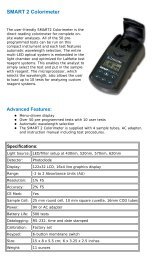
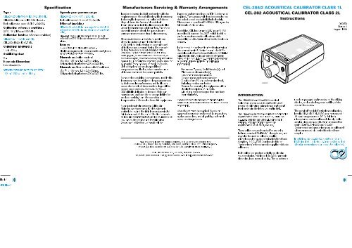
Type:CEL-284/2: Calibrator to IEC 942 Class 1L,CEL-282: Calibrator to IEC 942 Class 2L,Both calibrators meet ANSI S1.40-1984.Calibration reference condition:20 o C, 101.3 kPa, and 65%RH.Calibration level: (at reference conditions)CEL-284/2: 114.0 dB ±0.3 dB,CEL-282: 114.0 dB ±0.5 dB.Calibration frequency:1 kHz ±5 Hz.Stabilising time:5s.Harmonic Distortion:Less than 0.5%.Output voltage: (CEL-284/2 only)100 mV RMS ±1 mV at 1 kHz.SpecificationOperating temperature range:CEL-284/2: +5 to +35 o C ±0.3 dB,Both calibrators: -10 to +50 o C ±0.5 dB.Effect of humidity:CEL-284/2: ±0.3 dB in the range 30 to 90%RHreferred to 65%RH, in the absence of condensation,CEL-282: ±0.5 dB in the range 30 to 90%RHreferred to 65%RH,in the absence of condensation.Battery:1 x 9 V (PP3; IEC 6F22; IEC 6LR61).Alkaline manganese is recommended and gives abattery life better than 24 hours.Dimensions: (earlier versions)45 x 68 x 125 mm (1.8 x 2.7 x 4.9 in).Weight: (including battery) 230 g (0.51 lb).Dimensions: (later versions with 2/ serial no.)45 x 71 x 128 mm (1.8 x 2.8 x 5.0 in).Weight: (including battery) 250 g (0.55 lb).Manufacturers Servicing & Warranty ArrangementsIn order to ensure its rigid conformity with therequirements of the specification, this instrumentis thoroughly inspected and calibrated prior todispatch from the factory. All technicalinformation for an individual instrument is filedunder the instrument serial number. Therefore,the serial number should be quoted in anycorrespondence concerning the instrument.The manufacturers undertake to rectify anydefect in the instrument that is directlyattributable to faulty design or assembly, andwhich becomes apparent during the warrantyperiod. In order to take advantage of thiswarranty, the instrument must be returned,carriage paid, to the manufacturer’s factory oraccredited agent, where necessary repairs will becarried out. Normally the warranty period runs for12 months from the date of receipt of goods,with exceptions on certain specialisedcomponents supplied by other manufacturerswhich are warranted for shorter periods.Some of the specialised components used in thisinstrument may be subject to longer guaranteesby their actual manufacturers, and in all suchcases, the benefit of these undertakings will bepassed on to the user. However, CASELLACEL’s liability is limited to items of their ownmanufacture, and they do not accept liability forany loss resulting from the operation orinterpretation of the results from this equipment.A comprehensive Instrument CalibrationMaintenance Agreement (ICMA) scheme isavailable to extend the initial warranty period ofthis instrument. At the end of the first warrantyperiod, it is recommended that the equipment bereturned to the Service and Re-calibrationDepartment at Bedford, where it will beinspected and entered into the ICMA scheme asrequired. The warranty will then be extended forthe period stated on the individual schedule.Please contact your local CASELLA CEL agent forfull details of this service.In addition, CEL <strong>Instruments</strong> Ltd. has an UKASaccredited laboratory No. 0237 which is able toperform certain acoustic calibrations withtraceability to U.K. National Standards, details onrequest.In the event of a malfunction developing duringthe warranty period, the instrument should becarefully packed and returned either to CASELLACEL’s local agent, or in the case of domesticsales, to the CASELLA CEL Service Departmentat Bedford. Please include the followinginformation:Instrument Type(s), Serial Number(s) andFirmware version number(s),Customer name and address,Contact name and phone number,Details of any PC and software involved,including version number(s),Reason for returning the equipment with adetailed description of the fault,List of any error messages that may havebeen displayed.The necessary adjustments or repairs will becarried out, and the instrument returned as soonas possible.After the warranty has expired (except onapproved accounts) service work is undertakenagainst quotations, and all packing and transitcosts are charged extra.CEL and DAWE instrumentation is designed, manufactured, and serviced by:CASELLA CEL, Regent House, Wolseley, Kempston, Bedford, MK42 7JY, United Kingdom.Phone: (44) 1234 844100 Fax: (44) 1234 841490, e-mail: celsales@casella.co.ukCEL-284/2 ACOUSTICAL CALIBRATOR CLASS 1LCEL-282 ACOUSTICAL CALIBRATOR CLASS 2L<strong>Instruction</strong>sINTRODUCTION890032The CEL-284/2 and CEL-282 AcousticalCalibrators are an accurate and easily usedmeans of calibrating microphones and soundlevel meters in the laboratory and in field.The CEL-284/2 has been designed to satisfy therequirements of IEC 942 Class 1L, while theCEL-282 satisfies the Class 2L standard. Inaddition, both instruments meet therequirements of ANSI S1.40-1984.These calibrators are intended for use withindustry standard “half-inch” microphones, andmay also be used to calibrate smallermicrophones by means of suitable MicrophoneCouplers. A CEL-4725 Coupler suitable for“quarter-inch” microphones is supplied with thecalibrator.060050Issue: 4August 1999used are pre-aged and matched to the drivingcircuits, so that the long term stability of thesystem is assured.The nominal free field (equivalent) calibrationlevel is 114.0 dB (101.3 kPa) at a frequency of 1kHz and temperature of 20 o C. Half-inchmicrophones can be calibrated directly, whilesmaller sizes such as CEL 9 mm mounted (onearly CEL-272, D-1423D and CEL-281Dosemeters) and quarter-inch can be calibratedwhen connected via a suitable microphonecoupler.In addition, the CEL-284/2 provides a 100 mVRMS signal at 1 kHz via a 3.5 mm socket so thatvibration measuring systems may be calibrated.17 Old Nashua Road #15, Amherst, NH 03031, U.S.A.Phone: (1) 603 672 0031 Fax: (1) 603 672 8053 e-mail: cel_sales@compuserve.comBoth calibrators produce a highly stable sinewave excitation, with less than 0.5% harmonicdistortion, in an acoustic cavity. The transducersBlack 1CEL Blue 1
SCHEDULE OF PARTSA complete “CEL-284/2 Acoustical Calibrator”consists of the following items.CEL-284/2 Calibrator (Class 1L),CEL-4725 Microphone Coupler (¼"),016003 (1 off) Battery, (IEC type 6F22),060050 Handbook.PREPARATION FOR USEMake the instrument ready for use by installing asingle 9 V battery. Zinc carbon (IEC 6F22) andnickel cadmium (rechargeable) batteries aresuitable.However, for the most reliable operation withlongest battery life, a manganese alkaline batteryis recommended.CautionMake sure the instrument isswitched OFF while a battery isbeing connected.The battery compartment is exposed by slidingopen the cover on the rear of the instrument.Fix the battery terminals firmly to the battery leadconnectors and ensure correct polarity. Replacethe cover after loading and clip it securely inplace.A complete “CEL-282 Acoustical Calibrator”consists of the following items.CEL-282 Calibrator (Class 2L),CEL-4725 Microphone Coupler ( 1 ⁄4"),016003 (1 off) Battery, (IEC type 6F22),060050 Handbook.Check the battery condition by switching theinstrument on, and ensuring that the indicatorlamp is lit for only about one second. If theindicator remains lit or does not light at all,replace the battery.The instrument is now ready for service. (If thecalibrator is to be out of service for long periods,remove the battery.)890022OPERATION<strong>Field</strong> Accuracy Check (Acoustic Calibration)Perform a field accuracy check (acousticcalibration) with the CEL-284/2 or CEL-282immediately before and after measurements aremade with a sound level meter or soundmeasuring system as follows.CautionMake sure the microphone,calibrator and coupler (when used)are correctly aligned, asmicrophone damage can be causedby the firm pressure required toovercome the resistance of the “O”ring seals in both calibrator andcoupler.A very small amount of siliconegrease may be used to lubricate theseals; however, do not allow greaseto enter the vent holes in themicrophone.1. With a quarter-inch microphone, first insert themicrophone into the cavity of the CEL-4725Coupler (supplied with the calibrator),ensuring that it makes contact with theshoulder in the cavity.measuring instrument), ensuring that itmakes contact with the shoulder in the cavity.3. Insert the coupler (complete with microphone)into the calibrator cavity, again making surethat it makes contact with the shoulder.To aid removal, the coupler flange is designedNOT TO fit flush against the calibrator rim.4. With a half-inch microphone, insert themicrophone directly into the calibrator cavity,ensuring that it makes contact with theshoulder in the cavity.5. Switch the measuring instrument ON.6. Select a suitable measuring range andfrequency weighting for the calibration; referto the relevant handbook.7. Switch the calibrator ON to obtain a nominal114.0 dB at 1 kHz (at standard temperatureand pressure - STP: 20 o C:101.3 kPa:65%RH).8. Wait 20 s for both calibrator and measuringinstrument reading to stabilise.The display should indicate the level shownfor a particular microphone or instrument inthe table. Refer to the graph for anycorrection that may be applied to this level.9. If necessary, adjust the calibration control ofthe measuring instrument until it gives theindication required by the table and graph.CalibrationLevel (dB)115114113112111MicrophoneTypeNominal SLMCalibrationLevel dB1 ⁄2" TypesCEL-186/2FCEL-186/2RPCEL-186/3FCEL-192/1FCEL-192/2FCEL-192/2RCEL-192/3FCEL-250/MK 250CEL-292B & K 41331 ⁄4" Types 2 Post1/1/96On Preamp.CEL-485CEL-230RFT MK 301On SLMCEL-231/D-1405ECEL-254/D-1422CCEL-269/D-1421DOn DosimeterCEL-6685CEL-425CEL-272/D-1423DCEL-281MicrophoneCorrectionFactor 1 dB60 70 80 90 100 110 120 Pressure(kPa)Example:At an ambient pressure of724 mmHg, the calibratorgives a level of 113.6 dB.This is the calibration levelto which the sound levelmeter must be adjusted.2. With a CEL 9 mm mounted microphone, firstPressureinsert the microphone into the cavity of a400 500 600 700 800 900 (mm Hg)CEL-6050 Coupler (supplied with the 890023113.6113.6114.0113.6113.6113.6113.6113.6113.6113.6114.0113.8114.0114.2114.0113.8114.0114.0113.7113.8Pre1/1/96114.0114.0114.0114.0114.09 mm Types 3 Pre1/1/96On dosimeterCEL-272/D-1423DCEL-281114.0114.0Post1/1/96-0.2-0.2+0.2-0.2-0.2-0.2-0.2-0.2-0.2-0.2+0.2NA+0.2+0.4+0.2NA+0.2+0.2-0.10Pre1/1/96+0.2+0.2+0.2+0.2+0.2Pre1/1/96+0.2+0.21 Add this factor to the pressure level only when such alevel is given on an appropriate calibration certificate.2 Use CEL-4725 Coupler.3 Use CEL-6050 Coupler.10. After use, switch the calibrator OFF, andremove it and any coupler from themicrophone.The sound pressure level within the calibrationcavity varies from one microphone type toanother, depending on the actual working volumeexcited; refer to the table for details.Accelerometer Calibration (CEL-284/2 only)InstrumentCautionDO NOT attempt to performsimultaneous acoustic andelectrical calibrations as theacoustic level changes when a plugis inserted into the 100 mV outlet.Immediately before and after takingmeasurements, calibrate a vibrationmeasurement system using the electricalmethod and employing the CEL-284/2 as follows.1. Remove the accelerometer lead from themeasurement system and replace it with aC5681/1 Cable that has a 3.5 mmsub-miniature jack-plug using ring as signal,and tip and sleeve as ground.2. Insert the 3.5 mm sub-miniature plug at thefree end into the socket on the calibrator.The CEL-282/4 and CEL-282 AcousticalCalibrators comply with the EMC Directive89/336/EEC of the European Union. They havebeen tested according to the standard deliveryschedule and comply with the followingstandards.EN 50081-1: 1992 & EN 50081-2: 1993Generic emission standards for residential,Class 1LCalibratorCEL and Dawe Equivalent IdentitiesClass 2LCalibratorDigital SoundSurvey MeterVariations in atmospheric pressure both ataltitude and at sea level will also have an effecton the acoustic calibration level, and follow thecurve shown in the graph. It is recommendedthat a barometer be used to measure airpressure during calibration, to determinewhether the indicated calibration level needs tobe corrected.3. Switch the vibration measurement systemON.4. Select a suitable measuring range for thecalibration, refer to the relevant handbook.5. Wait for the measuring system to stabilise.6. Switch the calibrator on to obtain 100 mV at1 kHz and wait 5 s for it to stabilise.7. Check that the measuring system indicatesthe level required by the relevant handbook.8. If necessary, adjust the calibration or levelcontrol on the measuring system until itgives the correct indication.9. Switch the calibrator off, and disconnect itafter use.Compliancecommercial, light industry and industrialenvironments.EN 50082-1: 1992 & EN 50082-2: 1995 Genericimmunity standards (for both RF fields andelectrostatic discharge) for residential,commercial, light industry and industrialenvironments.Digital ImpulseSLMDigitalIntegrating SLMPersonal SoundExposure MeterCEL Identity CEL-284/2 CEL-282 CEL-231 CEL-254 CEL-269 CEL-272Dawe Identity D-1418D D-1411E D-1405E D-1422C D-1421D D-1423DBlack 2CEL Blue 2