cg-550/030/a/gt/hp maintenance & operating instructions - Field ...
cg-550/030/a/gt/hp maintenance & operating instructions - Field ...
cg-550/030/a/gt/hp maintenance & operating instructions - Field ...

You also want an ePaper? Increase the reach of your titles
YUMPU automatically turns print PDFs into web optimized ePapers that Google loves.
CG-<strong>550</strong>/<strong>030</strong>/A/GT/HPMAINTENANCE & OPERATING INSTRUCTIONSWITHREPAIR PARTS LISTSERIAL #______________________________
SAFETY DATAPLEASE READ AND HEED THE FOLLOWING IMPORTANT SAFETY NOTICES BEFOREPLACING MACHINE IN SERVICE.* * * * NOTICE * * * *PROPER PERSONAL PROTECTIVE EQUIPMENT, INCLUDING, BUT NOT LIMITED TO:GOGGLES, DUST MASKS OR RESPIRATORS, GLOVES, HARD HAT, BOOTS AND RAINGEARMUST BE WORN WHEN OPERATING THIS EQUIPMENT.* * * * NOTICE * * * *FOLLOW MATERIAL MANUFACTURER’S INSTRUCTIONS FOR PROPER MATERIAL USEAND RECOMMENDATIONS FOR SAFETY EQUIPMENT AND PROCEDURES.* * * * WARNING * * * *NEVER PUT HANDS OR TOOLS IN MIXERS OR PUMP UNLESS PRIMARY POWER SOURCE ISSHUT OFF AND DISCONNECTED AND KINETIC ENERGY DISSIPATED. ON ELECTRICALLYPOWERED EQUIPMENT, USE PROPER LOCK OUT/TAG OUT PROCEDURES. FAILURE TOOBSERVE THIS WARNING COULD RESULT IN SERIOUS PERSONAL INJURY AND/ORDAMAGE TO THE MACHINE.* * * * WARNING * * * *NEVER ATTEMPT TO DISCONNECT OR OPEN THE COUPLING ON ANY PART OF THE PUMPDISCHARGE SYSTEM WHILE PUMP IS IN OPERATION, OR IF THE DISCHARGE SYSTEM ISUNDER PRESSURE FOR ANY REASON.* * * * WARNING * * * *NEVER OPERATE MACHINE WITHOUT THE VARIOUS GUARDS, SHIELDS AND OTHERSAFETY EQUIPMENT WITH WHICH THE MACHINE WAS ORIGINALLY EQUIPPED IN PLACEAND FUNCTIONAL.* * * * WARNING * * * *ALL ELECTRICAL CONNECTIONS MUST BE MADE BY A QUALIFIED ELECTRICIAN.* * * * WARNING * * * *HYDRAULIC COMPONENTS, INCLUDING, BUT NOT LIMITED TO VALVES, FITTINGS,HOSES, MOTORS, RESERVOIR AND FILTERS MAY BE HOT. TO PREVENT INJURY, TOUCHONLY THE HANDLES PROVIDED. LET THE HYDRAULIC COMPONENTS COOL BEFORESERVICING THE EQUIPMENT.®
TABLE OF CONTENTSSECTIONSUBJECT1. GENERAL DESCRIPTION2. OPERATING INSTRUCTIONS3. GROUT SUGGESTIONS4. DIAGRAM & REPAIR PARTS LIST5. GROUT PUMP INSTRUCTIONS6. AIR MOTOR INSTRUCTIONS®
SECTION 1GENERAL DESCRIPTION®
CG-<strong>550</strong>/<strong>030</strong>/A/GT/HPGENERAL DESCRIPTIONThe ChemGrout Model CG<strong>550</strong>/<strong>030</strong>/A/GT/HP is a pneumatically powered, skid mountedcement grout plant specially designed and constructed for application in the geothermalindustry. The machine consists of one 70 gallon capacity vertical shaft paddle mixer andone CG-<strong>030</strong> single acting piston type grout pump. An oversize 6” diameter mixerdischarge gate facilitates discharge of thick mixes into a 50 gallon capacity hoppersituated directly above the pump. The grout pump is driven by a 8” diameter selfreciprocatingcylinder, which allows the pump to produce discharge rates up to 16 GPMand pressures up to 700 PSI. The extra large capacity hopper makes continuousoperation possible. A 30 gallon capacity water batcher (OPTIONAL) is installed over themixing tank to facilitate quick batching.All pump components are assembled with horseshoe shaped pins making assemblyand disassembly for cleaning and <strong>maintenance</strong> easily accomplished with no specialtools required.Simplicity of design and construction ensures years of dependable service with properand timely <strong>maintenance</strong>.Dimensions: 76” X 31” X 51” (78” with water batcher.)Weight: 750 lbs®
SECTION 2OPERATING INSTRUCTIONS®
OPERATING INSTRUCTIONSGENERAL* * * * WARNING * * * *NEVER PUT HANDS OR TOOLS IN MIXERS OR PUMP UNLESS PRIMARY POWERSOURCE IS SHUT OFF AND DISCONNECTED. FAILURE TO OBSERVE THISWARNING COULD RESULT IN SERIOUS PERSONAL INJURY AND/OR DAMAGE TOTHE MACHINE.SET-UPIn general, the most important factors in setting up are proximity to the work and accessto materials and water supply; consideration should be given to the disposal of wastematerials and wash-out residue.It is always best to keep grout lines as short as possible to reduce pumping distances.This is particularly important when pumping hard-to-pump materials, such as sandedgrouts and pre-blended materials.The source of solid materials (cement, fly ash, sand, etc.) should be readily accessibleand an adequate supply of water should be available for mixing and clean-up.When planning a project for high production rates, it is well to remember that thegreatest consumption of time occurs when charging the mixers. A proper set-up canreduce this to a minimum.START-UPAfter set up, visually inspect that there are no foreign objects or old set up materials ineither the pump or the mixer(s), then make all necessary connections.With <strong>operating</strong> levers, valves, or handles in either "NEUTRAL" or "OFF" position and theprimary power source turned OFF, fill the pump hopper with clear water. NOTE: It maybe necessary to elevate the discharge hose during this operation to prevent waterexiting through the ball valves.®
OPERATING INSTRUCTIONS (cont'd)Turn on the primary power source and observe that conditions are normal and machineis ready to run.Check each mixer for proper operation by running the mixer in both forward and reversedirections, if unit is so constructed as to allow reverse direction.Next, start the delivery pump to discharge the water that was previously introduced intothe pump hopper. This is an ideal opportunity to check the grouting system to determinethat all lines and hoses are clear and unobstructed. Pump condition may also bechecked at this time by testing discharge pressure.When it is determined that all systems are normal, shut off the pump and drain thewater from the pump and all lines.NOTE: Some pre-blended materials and some on-site mixes of sand and cement tendto separate and clog the hoses upon contact with residual water. To prevent thisoccurrence, it's a good procedure to mix and pump out a cement/water slurry prior tomixing and pumping the production material, to lubricate the pump and hoses.PRODUCTIONDuring the production phase of the work, monitor pump and mixer performancecontinuously, being alert to any signs of abnormality.Keep mixers free of material build-up, keep the outside of the machine clean, and keeppump packing lubricated and just tight enough to prevent leakage. (Section 5)CLEAN-UPAfter disposing of excess production materials, carefully wash out mixer tanks, paddlesand baffles into the pump hopper and pump the resulting washout material through thegrout hoses to a suitable disposal site. Continue this operation until only clear water isdischarged.It is advisable to drain all residual wash water from the pump and all hoses whenwashout is complete.CAUTION: NEVER RUN PUMP WITHOUT FLUID AS IT WILL CAUSE SEVEREDAMAGE TO PISTON AND SLEEVE.®
SECTION 3GROUT SUGGESTIONS®
Please note that the information contained in this sectionis general in nature, and not specific to geothermalmaterials, which possess their own unique characteristicsand preparation procedures.®
MIXING AND PUMPING SUGGESTIONSNOTE:The suggestions offered herein are intended as an aid to help the operator identifysome of the factors that need to be taken into consideration when mixing and pumpingcementitious grouts. Because a wide variety of materials are available for many differentapplications, it is incumbent upon the operator to become familiar with the specificcharacteristics of the material he intends to use.MATERIALSAmong the commercially manufactured materials available in today’s market arematerials for structural repairs, floor toppings, high stren<strong>gt</strong>h non-shrink grouts, manholeand sewer lining mortars and other specialty materials. Each of these materials hasunique characteristics, which must be well understood to insure a successfulapplication.FLOWIn general, most materials need to be of a flowable or pourable consistency forsuccessful pumping. This means that if the material can be poured out of a pail orbucket, it can likely be pumped. The exception to this requirement is repair mortars,which tend to be mixed in a thicker consistency and require special pumpin<strong>gt</strong>echniques. Materials that contain aggregates pump best and perform best when theconsistency is kept to the lower range of pourable; that is, not too wet.SETTING TIMESome materials contain accelerating admixtures to reduce the setting time. This isparticularly true of repair mortars and other spray applied materials so that stren<strong>gt</strong>h gaincan be fairly rapid. It is important to keep moving when using these types of materials.Once the material is mixed, it must be pumped immediately and kept in motion andsubsequent batches must be mixed and pumped as rapidly as possible. Any delays inthe application process could result in plugged hoses and equipment. Temperature alsohas an effect upon these materials to the extent that exposure of the hose to the sun ona hot day will accelerate the set time even more; therefore this should be avoided. Itmay even be necessary in some cases to cool the material, the mix water, or even thehose itself.PUMPING DISTANCEPumping distances should always be kept to a minimum, and hoses should run asstraight as possible no matter what material is being used. Sometimes circumstancesrequire longer than usual hose len<strong>gt</strong>hs; when this occurs, every effort should be madeto use every advantage possible to insure a successful application. Some materialssimply cannot be pumped for long distances, so it’s best to know the proposed materialcharacteristics before attempting a production procedure.®
MIXING AND PUMPING SUGGESTIONS (Cont’d.)GENERAL PROCEDURESBefore attempting to mix and pump production materials, it is prudent to rinse the mixerand charge the pump hopper with sufficient water to thoroughly flush the pump and allgrout lines. This is to purge the grouting system of any residual materials or scale thatmay exist. Once that is completed, remove the grout hose from the pump and drain outall water by elevating one end, or by progressively elevating the entire hose, starting atone end and proceeding to the other.Next, mix a slurry composed of portland cement in approximate proportions of 6-1/2 to7-1/2 gallons of water to one bag (94 lbs.) of cement, and pump this through thegrouting system. This is to remove any residual water from the hose, lubricating it forthe production material to follow. Now the production grout may be mixed and pumpedimmediately behind the slurry mix, which is thus evacuated from the hose, and may beretrieved in a bucket. Do not attempt to pump production material through a dry hose.Finally, one last word about procedures. Occasionally, no mater how conscientious anoperator may be, a hose will get plugged. Once this happens, the only sure way toremove the plug is to empty it of material. Beating on it with a hammer or running over itwith a vehicle will not usually be successful. A prudent operator will be prepared forsuch eventuality by having readily available a sufficient len<strong>gt</strong>h of small diameter stifftubing, hose or plastic pipe to which he can rapidly connect a water source and flush thegrout from the hose.®
ADDITIONAL SUGGESTIONS“HOMEMADE” GROUTSometimes commercially prepared grouts are not readily available, and in these cases itmay be necessary to formulate and produce the material on site. This can be done quitesuccessfully, but certain basic principles must be observed.The resultant material should exhibit the following characteristics:1. A stable suspension of solids that does not separate while at rest.2. Color must be predominantly that of the cement used.3. Fluid enough to pour from a container but not too wet. (Thick batter consistency orthicker)CEMENTThere are several types of Portland cements manufactured to satisfy a variety ofspecific requirements, such as high early stren<strong>gt</strong>h, sulfate resistance and other needs.The most common of these is Type I Portland, and is that which is most frequently usedin the production of cementitious grout.WATERIn most instances, the water to be used for the production of grout should be clean andfree of sulfates or other dissolved chemicals. If available, potable water is ideal. Sincethe water to cement ratio is the most important factor in the quality of the material in itsfinal state, the water content should be kept to the minimum that will produce materialswith the characteristics listed above.ADMIXTURESAdmixtures are available to modify and enhance the grout mixture. These includeplasticizers, water reducing agents, expansive agents, anti-washout ingredients, settime modifiers and others. Each of these admixtures are designed to impart specificproperties to the grout. If used at all, they should be used only with a full understandingof their effects, and only according to the manufacturers’ recommendations.FLYASHIn some parts of the country, flyash (a byproduct of coal burning power stations) isavailable. This material has often been used to enhance the properties of cementitiousgrouts or, in some cases to reduce the cement fraction. Use of this material should beapproached with CAUTION, since ash from some sources have, in recent years, beenobserved to cause FLASH SET in grout mixes. If the use of this product is anticipated,trial mixes should be made to prove their applicability.®
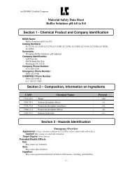
ADDITIONAL SUGGESTIONS (Cont’d.)SANDSand is often used in grout formulations either to increase the volume of the material,thus reducing the cost, or to act as an aggregate in the case of high-stren<strong>gt</strong>h structuralgrouts. If the use of sand is anticipated, several factors must be considered such as theshape, size and gradation of the sand to be used. In general, the sand should be clean,well graded and of rounded, natural shape. Angular particles such as those found inmanufactured sands should be avoided.Of all of the considerations when anticipating the use of sand in a grout mixtureintended to be pumped, one of the most important is gradation. Gradation of a sandsample is determined by a sieve analysis, which reveals the percentages of eachindividual particle size of which the sand is composed. Laboratory tests and fieldexperience shows that some sand gradations will pump better than others, and somewill pump only with difficulty, if at all. Sample sieve analysis data is offered herein as aguide to choosing sand that has a good chance of producing a strong, pumpable groutmix.Another factor to take into consideration when choosing a sanded grout over a slurrygrout is the volume, or amount of sand that can be used in the mix. This will vary as afunction of the gradation, but in general will usually be in the proportion of 1-1/2 to 2times the cement content by VOLUME. In rare cases, it may be possible to exceed thisproportion, but caution should be exercised.Grouting Sand Gradation SpecificationsSieve Size% Passing#8 100#16 90-100#30 55-80#50 30-55#100 10-30#200 0-10NOTE:The suggestions above are primarily for conventional portland cement based grouts. Itis recognized that geothermal work utilizes special mixes, therefore, it is incumbentupon the operator to learn the characteristics of the material he will be using.®
U. S. Standard Sieve Numbers1003/8 4 8 16 30 50 100 200090Materials with gradation curves to the rightof these limits usually ARE pumpable.1080207<strong>030</strong>Percent Passing by Weight60504<strong>030</strong>Materials with gradation curves to the leftof these limits usually are NOT pumpable.40506070Percent Retained by Weight20801090010010 5 1 0.5 0.1 0.05 0.03Particle Size in Millimeters®
SECTION 4DIAGRAM & REPAIR PARTS LIST®
14 151727A10 10A17A182122231923 3A 3B3419A 202A331631A925247322928 28A312616CG-<strong>550</strong>/<strong>030</strong>/A/GT
CG-<strong>550</strong>/<strong>030</strong>/A/GT/HPCOMPONENT PARTS LISTREF # PART # DESCRIPTION1 63<strong>030</strong>A Grout Pump2 21<strong>030</strong>SCN50 Hopper Screen2A 21<strong>030</strong>HOP50 Hopper3 846SLIDE 6" Slide Valve Assembly3A 546GATEGASK Discharge Gate Gasket3B 33TBC7112 T Bolt Gasket Clamp6 06CYL8X7 8” X 7” Air Cylinder7 84<strong>030</strong>RELIEF Grout Pressure Relief Valve9 06NAN5000N06 Exhaust Silencer10 06M05 ½” Muffler10A 06M05A Replacement Element14 046AMNRV11 Mixer Air Motor (Gast)15 04K208 Air Motor Repair Kit (Gast Motor only)14* 04SM6AMAN Alternate Air Motor (Ingersoll Rand)15* 04SM6AMA-TK1 Repair Kit (Ingersoll Rand)16 06LUB15 ¾” ASL Air Line Oiler17 30SW050T 15:1 Gearbox17A 21WINBASE Gearbox Base18 21PADCPLGH 1” Paddle Coupling19 2130PAD Mixer Paddle19A 21PADBUSH Paddle Bushing20 21PADPIN Paddle Pin21 2130BAGBKR Mixer Guard / Bag Breaker22 2130COV Cover For 27" Mix Tank23 84BBLV50 Mixer Air Valve24 542VICT#77 2” Victualic Clamp25 33EV11/4ABR 1-1/4” Part A Evertite Coupling26 21050REDUCE11/4 2” to 1 ¼” Reducer27A 2130DUSTCOV Mixer Cover28 33AM13 1” Air Connection28A 06CRAP2 30 Mesh Air Filter29 06NAF5000N010 1” Air Line Filter31 06NAL5000N010 1” Air Line Lubricator31A 06FRL1 1” Filter/Regulator/Lubricator Assembly32 841BBALL Pump Control Valve33 06NVSA-ALT Directional Control Valve34 061/8CHECK 1/8” Brass Check Valve* Machine may be equipped with Gast or I/R motor.** Complete sets of warning labels are available upon request®
SECTION 5GROUT PUMP INSTRUCTIONS®
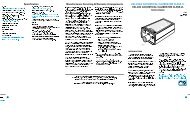
1715 13 26 20185B122727162122143A1010C310E57A43A6A66A1A2A222199A931110B10A83A73412A2C2BCG-<strong>030</strong>/A/HP Parts Diagram
CG-<strong>030</strong>/A/HPCOMPONENT PARTS LISTREF. PART NO. DESCRIPTION1 21<strong>030</strong>REDUCER-02C CG-<strong>030</strong> Reducer (3” X 2” Victaulic)1A 24<strong>030</strong>RBOLT CG<strong>030</strong> Reducer Bolt (3/8-16 X 3-1/3)2 21050REDUCE11/4 2” Victaulic X 1-1/4” NPT Reducer2A 542VICT#77 2” Victaulic Coupling (With Gasket)2B 33EV11/4ABR 1-1/4” Part A Evertite Coupling2C 84<strong>030</strong>RELIEF Grout Pressure Relief Valve3 21<strong>030</strong>STAPLE CG-<strong>030</strong> Staple Pin3A 33EV3GASK Coupling Gasket4 21<strong>030</strong>BALL 2-5/8” Polyurethane Ball5 See Main Parts List Hopper5A See Main Parts List Hopper Screen6 21<strong>030</strong>BALLSEAT3 CG-<strong>030</strong> Ball Seat6A 21<strong>030</strong>RING “O” - Ring For Ball Seat7 21<strong>030</strong>TEE CG-<strong>030</strong> Tee7A 24<strong>030</strong>TBOLT Hopper Ball Retainer (3/8-16 X 4-1/2)8 21<strong>030</strong>SLEEVE CG-<strong>030</strong> Sleeve9 21<strong>030</strong>CYLBKTA CG<strong>030</strong> Air Cylinder Bracket9A 21<strong>030</strong>CYLBKTAHP CG<strong>030</strong> Air Cylinder Bracket Adapter10 07<strong>030</strong>PIST Piston Assembly (parts 10A to 11)10A 21<strong>030</strong>PISTBP CG-<strong>030</strong> Piston Backer Plate10B 21<strong>030</strong>PISTSP CG-<strong>030</strong> Piston Spacer Plate10C 21<strong>030</strong>PISTCUP CG-<strong>030</strong> Piston Cup10E 243/4X10JAMNUT Piston Nut11 21<strong>030</strong>AIRADAPT CG-<strong>030</strong> Piston Adapter12 06NAN500N06 Exhaust Silencer13 06FRL1 1” Filter/Regular/Lubricator14 06NAR5000N010 1” Regulator15 06NAL5000N010 1” Lubricator16 06NAF5000N010 1” Filter17 841BBALL 1” Ball Valve18 33AM13 1” Air King Fitting19 06CYL8X7 8" Bore X 7" Stroke Air Cylinder20 06CRAP2 30 Mesh Air Filter21 06NVSA-ALT 1” 2 Pos., 4 Way Dir. Ctrl. Valve22 06VR370 Air Bleeder Valve (directional control)26 292160 Pressure Gauge27 061/8CHECK 1/8” Check Valve®
<strong>030</strong> GROUT PUMPMaintenanceDaily - add oil SAE 10 or SAE 20 at (15) Drain filter (16).OperationConnect air line to (18) and grout line to (1). Pour 5 gallons water in hopper (5). Startpump by opening valve (17) and pump out water. Disconnect and manually drain hose.Reconnect grout hose. Begin mixing by introducing first water, then solid materials tomixer. Mix until smooth and creamy, then discharge into hopper and begin pumping -see IMPORTANT NOTICES below.CleanupPour water into (5) and pump until discharge is clear. Stop pump, disassemble, washand clean. Reassemble pump immediately when clean to prevent loss of parts.Important NoticesSome pre-blended grouts not pumpable. Granular particles in grout must be wellgraded. Maximum particle size in slurry 3/16" (.5 cm.). Grout mix must not be too wet.See section on grout mix recommendations.®
SERVICE GUIDEPROBLEM PROBABLE CAUSE SOLUTIONPumps water O.K., willnot pump grout.Grout mix too "thick", doesnot enter pump chamberAggregate too large,preventsball from seating.Aggregate segregations inDischarge hose. (“SandPlugs”)Add water to grout mix, butbe careful not to dilute mix soMuch as to cause aggregateto segregate.Change to smalleraggregate, or screen outlarger particles.Drain residual water fromDischarge hose prior topumping grout.Aggregate improperlygraded;change aggregate.Pump stalls on dischargestroke.Pump runs but does notdischarge.Piston will not reversedirectionPump strokes unevenlyor too slowly.Grout material hasexcessive Coefficient ofinternal friction.Pump discharge or hoseplugged with grout.Grout not entering pumpChamber.Directional valve spool“stuck”Misadjusted shuttle valve.Some premixed groutmaterials are not pumpable.See section on grout mixrecommendations.Disconnect discharge hose,check pump, clean out hose.Grout too "thick" orobstruction in hopper.Shift spool manually withsmall diameter object, suchas a nail or awl.Readjust shuttle valveadjusting screws (13); turnout to increase speed and into decrease speed.®
SERVICE GUIDE cont’dPROBLEM PROBABLE CAUSE SOLUTIONPump does not run. Insufficient air supply. Check air at source.Require30 CFM at 100 PSI.Pump fluid end plugged. Remove staples (3),disassemble pump andcheck sleeve (3) forobstruction.Directional valve spool“stuck”Obstruction in air supplyline or filterShift spool manually withsmall diameter object,such as a nail.Disconnect air line,determine clear. Removecover and clean air filter.Low discharge Low air pressure. Check air supply pressure;pressure. Should be 100PSI.Grout or fluid leakagearound piston.Excessive clearancebetween piston andsleeve.Replace piston cupsExcessive piston wear Dirty or scored sleeve. Clean residual materialfrom sleeve (8), or replacesleeve, if scored.®
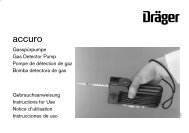
EXPLANATION OF AIR CYLINDER TIMING SEQUENCE DIAGRAMVALID FOR CG-<strong>030</strong> AND ALL AIR DRIVEN RECIPROCATING PUMPSFIGURE 1In this picture, air is entering the cylinder through Port B, driving the piston forward,while exhaust air is exiting from Port A through the timing valve (1). While in motion, theair pressure at pilot ports (4) and (5) is equal to line air pressure.FIGURE 2In Figure 2, the piston has traveled to its fully extended len<strong>gt</strong>h and engaged poppetvalve (2), allowing the escape of a small amount of air from the pilot system. Release ofthis air has reduced the air pressure at timing valve pilot port (5), resulting in a pressureimbalance, causing the timing valve spool to shift, directing drive air through Port A,reversing direction of piston travel.FIGURE 3As the piston rod retracts, air pressure in the pilot system is again equal to linepressure, and exhaust air is expelled from the rear of the cylinder through Port B whiledrive air is entering the cylinder through Port A.FIGURE 4The piston has reached its maximum retraction travel and engaged poppet valve (3),resulting in a reduction of air pressure at pilot port (4). This causes the timing valvespool to shift, directing drive air to the cylinder through Port B. The piston is now movingforward again as exhaust air exits the cylinder through Port A.®
TIMING SEQUENCE DIAGRAMCHEMGROUT AIR POWERED PISTON AND PLUNGER PUMPS2 323ABABFig. 1( + )AB( + )5Fig. 2( + ) ( - )AB414 1 52 32 3ABABFig. 4( - )AB( + )5Fig. 3( + )AB( + )54141®
SECTION 6AIR MOTOR INSTRUCTIONS®
AIR MOTOROperating and Maintenance InstructionsConstructionYour air motor is a precision built rotary type motor. The vanes will last 5,000-15,000hours depending upon speed, method of oiling, <strong>operating</strong> pressure, and the precautionstaken in maintaining the motor. The type of shaft seal used does not lend itself to<strong>operating</strong> pressures above 100 PSI.GuaranteeAir motors are guaranteed against defects in material or workmanship (normal wear ofparts excluded) for a period of one year from factory ship date. Unit failing withinwarranty will be rebuilt or replaced at manufacturer's discretion, F.O.B. factory.Maximum liability not to exceed original purchase price of unit involved. Allowing excessmoisture or foreign particles from the air line to enter the motor will nullify the guarantee.InstallationInstall a moisture trap and filter in the air line ahead of motor. For efficiency of outputand control of speed, use air lines the same size as or the next pipe size larger than theintake port of the motor. If <strong>operating</strong> intermittently without automatic air line oiler placemotor in accessible position for easy lubrication. A single rotation motor will operateproperly in only one direction. A reversible motor will work equally well in bothdirections. A 4-way valve which can be connected by piping to both air ports of themotor will make reversing possible. When coupling or connecting the motor to a drivenmember, avoid any end or side thrust on the shaft, and especially do not hammer onshaft.OperationThe starting torque is less than running torque and could vary depending on the positionat which the vanes stop in relation to the air intake port. The speed and torque can beregulated by using a pressure regulator or a simple shut-off valve to obtain desiredpower and conserve air. For moderate speeds (under 2,000 RPM) or intermittentoperation 1 squirt of oil in bearing oilers per day will suffice. For continuous duty orfrequent high speed operation, use an automatic air line oiler set to feed 1-3 drops perminute. The bearings will receive oil from the rotor chamber during automatic oiling.Use SAE No. 10 oil. Lubrication is necessary for the bearings, shaft seals, and rustprevention.Excessive moisture in the air line can cause rust formation in motor and might alsocause ice to form in muffler due to expansion of air through the motor. The moistureproblem can be corrected by installing a moisture separator in the line and also byinstalling and after cooler between the compressor and air receiver.®
ServicingIf the motor is sluggish or inefficient try flushing with solvent* in well ventilated area.Disconnect the air line and muffler and add several teaspoons full of solvent* Rotate theshaft by hand in both directions for a few minutes, again connect the air line and applypressure slowly until there is no trace of solvent* in exhaust air. (Keep face away fromexhaust air). Check the muffler felts for grease, dirt, etc. If dirty, wash them in solvent.Replace the felts and connect the muffler. Re-lubricate the motor with a squirt of oil inthe chamber and bearings oilers.If the vanes need replacing, or foreign particles are present in motor chamber, anexperienced mechanic may remove the end plate opposite the drive shaft end. Don'tpry with a screw driver as it will dent the surface of the plate and body causing leaks. Apuller tool should be used which will remove the end plate while maintaining the positionof the shaft. New vanes should have the edge with corners cut on angle or the notchededge (if reversible) towards the bottom of the vane slot. New gaskets should be theproper thickness onion skin otherwise motor will operate inefficiently and waste air. Theend plates should be replaced carefully using an arbor press with a pusher acting onboth races of the bearing while supporting the opposite (drive) end of the shaft rigidly.This will eliminate brinelling of the bearings and misalignment of rotor.*Recommended solvent for air motors and lubricated pumps is Gast Flushing Solventpart #AH255, or any non toxic, non flammable industrial cleaning solvent.DO NOT USE KEROSENE.®
SPECIAL INSTRUCTIONSAIR OPERATED EQUIPMENTWhenever compressed air powered equipment is used, it is the air compressor which isthe primary motive force to drive the equipment. Whether the compressor is driven by adiesel or gas engine, or an electric motor is immaterial. The important factor is itscapacity to provide a sufficient QUANTITY of air expressed in terms of CUBIC FEETPER MINUTE at a specific PRESSURE, usually expressed in terms of POUNDS PERSQUARE INCH. Thus, compressors are usually rated in terms of X CFM at Y PSI. (Forexample, 250 CFM at 120 PSI) Occasionally, you may see a horsepower rating, but itis much more common for compressors to be rated as previously described.In any event, the capacity to do work is directly related to the VOLUME andPRESSURE of the compressed air supply. Air powered equipment is designed toaccomplish specific tasks and therefore, requires a specific MINIMUM VOLUME ofcompressed air at a specific PRESSURE.With any air powered equipment, it's perfectly acceptable to use a compressor with ahigher volumetric capacity than the equipment requires, since the equipment will onlyuse the amount of air that it needs; however, the stated pressure capacity of theequipment should not be exceeded by more than 10%. Excess pressure can beharmful to the seals of air motors and cylinders and will significantly shorten the servicelife of the equipment.Attempts to run pneumatically powered equipment on compressors of lower capacitythan required will likely yield disappointing results.RECOMMENDATIONSWhen using air powered equipment, some simple rules and procedures will help assurea successful job:1. Keep compressor properly serviced with adequate fuel and engine oil and keepcompressor oil at proper levels. Drain condensation from receiving tank beforestart-up.2. Keep hose runs between compressor and machine as short as practical.3. Use air hose that is rated for the pressure capacity of the compressor and ofsufficient diameter to transport the volume of air that the compressor is rated todeliver. (In other words, use a BIG hose!)4. Never use air supply hose for any other purpose, and alwaysblow the hose out before connecting to equipment at the start of a working shift.®
Recommendations For Air Operated Equipment (cont'd)5. Keep equipment and line oilers full and clean filters and mufflers daily. Theobject is to provide an unrestricted flow of air TO and FROM the machine; moveit from the compressor to the machine as fast as possible, and when you'refinished with it, get rid of it as fast as possible. Also, remember that everythingneeds lubrication, including air motors and cylinders, so keep the oilers full.6. One final word: in temperate geographical zones, work is often done intemperatures between about 40 degrees F. and 60 degrees F. with relativehumidity that may reach as much as 100 percent. Because air is heated as it'scompressed and cools rapidly as it expands (like at the exhaust muffler of yourgrout plant), be on the lookout for ice. Since the expanding moist air can cool totemperatures below the freezing point, ice will frequently form around theexhaust ports of air motors and cylinders; when this happens, a restriction iscreated that may severely impair the operation of the equipment.The introduction of an Anti-freezing agent such as "Tannergas" through specialdispensers made for that purpose is the best way to prevent ice formation under theseconditions. If this isn't available, obtain and install an additional line oiler immediatelyafter the compressor and keep it filled with ethylene glycol anti-freeze.®