High pressure forged Sempell valves provide the ideal solution to ...
High pressure forged Sempell valves provide the ideal solution to ...
High pressure forged Sempell valves provide the ideal solution to ...

Create successful ePaper yourself
Turn your PDF publications into a flip-book with our unique Google optimized e-Paper software.
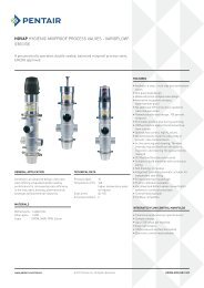
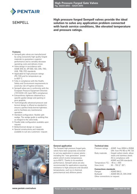
<strong>High</strong> Pressure Forged Gate ValvesFig. GA251.6012 – GA251.6015SEMPELL<strong>High</strong> <strong>pressure</strong> <strong>forged</strong> <strong>Sempell</strong> <strong>valves</strong> <strong>provide</strong> <strong>the</strong> <strong>ideal</strong><strong>solution</strong> <strong>to</strong> solve any application problem connectedwith harsh service conditions, like elevated temperatureand <strong>pressure</strong> ratings.Features• <strong>Sempell</strong> gate <strong>valves</strong> are manufacturedby using exclusively high quality <strong>forged</strong>materials <strong>to</strong> guarantee a superiorperformance and <strong>to</strong> sensibly decreaseoperating costs and delivery times.• Valve design in accordance withASME B16.34, API 600, ISO, DIN, TRD,VGB, TRB, PED standards.• Applicable for high <strong>pressure</strong> ratings(PN 720) and for temperature up<strong>to</strong> 650° C.• Fully in compliance with <strong>the</strong> Health,Safety and Environment requirements <strong>to</strong>avoid any risk of fugitive emissions.• <strong>Sempell</strong> <strong>valves</strong> are in conformity with <strong>the</strong>European Pressure Equipment Directiven°97/23/EC (CE mark 100% compliance).• Extraordinary tightness obtained by aspecific gasket design and packing inpure graphite.• Technologically advanced <strong>pressure</strong> sealbonnet design is offered as standard <strong>to</strong>ensure a perfect body-bonnet tightnessand <strong>to</strong> facilitate any maintenanceoperation.• Standard configuration: flexible splitwedge. The wedge guide is welding-freeas integral <strong>to</strong> <strong>the</strong> valve body.• Parallel slide configuration available uponrequest.• Bolted bonnet design on request.• Special constructions and materialsavailable <strong>to</strong> suit any cus<strong>to</strong>mers’ request.General applicationThe <strong>Sempell</strong> high <strong>pressure</strong> <strong>forged</strong> gate<strong>valves</strong> have been purposely conceived<strong>to</strong> suit any application in power plants -including <strong>the</strong> “new generation” powerplants which involve temperaturesup <strong>to</strong> 650°C. Thanks <strong>to</strong> its excellentperformance, <strong>Sempell</strong> <strong>valves</strong> are alsorecommended for applications requiringresistance <strong>to</strong> high <strong>pressure</strong>s and elevatedtemperatures, such as in chemical,petrochemical and offshore plants.Technical dataPressure ratings : ASME: from 900# <strong>to</strong> 4500#DIN: from PN 160 <strong>to</strong> PN 720Body materials : <strong>forged</strong> carbon steels, alloyssteels and stainless steels.All in compliance withASME and DIN standardsTemperature (°C) : -46 <strong>to</strong> + 650Sizes (mm) : 50 – 750 (2”-30”)Connections standardsFlanges : ASME B16.5.Buttweld : ASME B16.25, DIN 2448O<strong>the</strong>r connections on request.www.pentair.com/<strong>valves</strong>Pentair reserves <strong>the</strong> right <strong>to</strong> change <strong>the</strong> contents without noticeSEMLT-0005-EN-1306
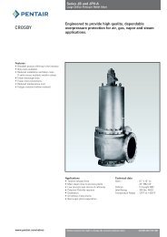
<strong>High</strong> Pressure Forged Gate ValvesPressure temperature ratings <strong>to</strong> ASMETest <strong>pressure</strong> <strong>to</strong> API 598 and ASME B16.34 (bar)Temp.Hydrostatic shell test Hydrostatic seat test Pneumatic test233 171 >5,6A105 / LF2 F11, F12 F22 F91 F316 A105 / LF2 F11, F12 F22 F91 F316(LCB) (WC6) (WC9) (CF8M) (LCB) (WC6) (WC9) (CF8M)C22.8 13CrMo44 10CrMo910 X10CrMoVNb91 X6CrNiNb1810 C22.8 13CrMo44 10CrMo910 X10CrMoVNb91 X6CrNiNb18101.046 1.7335 1.738 1.4903 1.455 1.046 1.7335 1.738 1.4903 1.455STANDARD CLASSWorking <strong>pressure</strong> (bar)°C ASME 900SPECIAL CLASS-29 - 38 153,2 155,1 155,1 155,03 148,9 155,2 155,2 155,2 155,03 155,150 150,2 153,4 153,6 155,03 144,4 155,2 155,2 155,2 155,03 152,1100 139,1 146,3 147,1 155,03 126,6 155,2 155,2 155,2 155,03 139,2150 135,7 139,1 139,9 150,55 115,5 155,2 155,2 155,2 155,03 125,8200 131,5 136,4 134,5 145,72 107 155,2 155,2 155,2 155,03 118,8250 125,2 133,4 132,7 137,46 100,2 155,2 155,2 153 155,03 111,4300 116,2 127,3 127,3 125,05 94,9 149,6 155,2 152,5 155,03 105,8350 110,9 120,7 120,7 121,61 91,3 144,4 147,5 152,3 151,58 101,5400 103,5 109,8 109,8 109,9 87,3 129,4 137,2 150,7 150,55 97,5425 86,3 105,3 105,3 105,07 86 107,8 131,6 149,1 148,82 96450 60,1 101,4 101,4 100,59 84,2 75,1 126,8 141,5 139,87 94500 26,4 83,4 83,4 93,02 80,5 33 104,2 107,1 124,02 89,8525 15,5 60,8 65,8 79,92 78,9 19,4 76 82,2 97,49 88,8550 38,3 49,1 75,1 74,9 47,9 61,4 86,81 88,8600 17,6 22,9 62,35 64,3 22,1 28,6 77,86 80,4650 29,63 42,4 37,21 53Test <strong>pressure</strong> <strong>to</strong> API 598 and ASME B16.34 (bar)Hydrostatic shell test Hydrostatic seat test Pneumatic test388 285 >5,6-29 - 38 255,3 258,6 258,6 258,37 248,1 258,6 258,6 258,6 258,37 258,550 250,4 255,7 256 258,37 240,6 258,6 258,6 258,6 258,37 251,8100 231,9 243,8 245,2 250,80 211 258,6 258,6 258,6 258,37 224,6150 226,1 231,9 233,2 243,22 192,5 258,6 258,6 258,6 258,37 202200 219,1 227,4 224,2 229,09 178,4 258,6 258,6 258,6 258,37 182,1250 208,6 222,3 221,1 208,42 166,9 258,6 258,6 255 258,37 170,3300 193,7 212,1 212,1 202,57 158,1 249,3 258,6 254,2 258,37 162350 184,8 201,2 201,2 195,68 152,1 240,6 245,8 253,8 252,52 156,3400 172,5 182,9 182,9 183,27 145,6 215,6 228,7 251,1 251,14 153,2425 143,8 175,5 175,5 175,01 143,3 179,7 219,3 248,3 248,04 150,9450 100,2 169 169 167,77 140,4 125,2 211,3 235,9 233,23 149,5500 44 139 139 154,68 134,1 55 173,7 178,5 206,7 144,9525 25,9 101,3 109,6 132,98 131,5 32,4 126,7 137 162,60 141550 63,8 81,8 125,40 124,8 79,8 102,3 145,03 136,3600 29,4 38,2 104,04 107,2 36,8 47,7 129,88 104,5650 49,61 70,6 62,01 65,7Test <strong>pressure</strong> <strong>to</strong> API 598 and ASME B16.34 (bar)ASME 1500Hydrostatic shell test Hydrostatic seat test Pneumatic test646 474 >5,6ASME 2500-29 - 38 425,5 431 431 430,62 413,6 431 431 431 430,62 430,950 417,3 426,2 426,7 430,62 401 431 431 431 430,62 422,4100 386,5 406,4 408,7 418,22 351,7 431 431 431 430,62 386,6150 376,9 386,4 388,6 405,13 320,9 431 431 431 430,62 349,4200 365,2 379 373,7 381,71 297,3 431 431 431 430,62 330,1250 347,7 370,6 368,5 347,26 278,2 431 431 425 430,62 309,4300 322,8 353,5 353,5 337,95 263,6 415,5 431 423,6 430,62 293,9350 308 335,3 335,3 325,90 253,8 401,1 409,7 423,1 420,98 282,1400 287,5 304,9 304,9 305,23 242,6 359,4 381,5 418,5 418,22 270,8425 239,6 292,5 292,5 291,45 238,9 299,6 365,6 414,1 413,4 266,6450 166,9 281,7 281,7 279,73 234 208,7 352,1 393,1 388,94 261,2500 73,3 231,6 231,6 258,03 223,6 91,6 289,6 297,5 344,5 249,5525 43,2 168,9 182,7 221,86 219,1 53,9 211,1 228,4 270,78 224,5550 106,4 136,4 208,77 208 133 170,4 241,49 224,5600 49 63,6 173,28 178,6 61,3 79,5 216,69 223,3650 82,68 117,1 103,35 197,1Pentair reserves <strong>the</strong> right <strong>to</strong> change <strong>the</strong> contents without notice page 2
<strong>High</strong> Pressure Forged Gate ValvesPressure temperature for ISO materialsPressure ratingTT 5 1.0460 15Mo3 13CrMo44 15NiCuMoNb5 10CrMo910 X10CrMoVNb91 X6CrNiNb1810(GS-C25) (GS 22Mo4) (GS 17CrMo55) (GS18CrMo910)1.0411 1.5415 1.7335 1.6368 1.7380 1.4903 1.455LF2 A105 F1 F11, F12 F22 F91 F316(LCB) (WCB) (WC6) (WC9) (CF8M)Temp.Working <strong>pressure</strong> (bar)°C Pressure rating 09 (PN 160)-50 200 166-29 - 38 200 200 220 320 16650 192 192 220 320 157100 185 185 220 320 148150 168 168 195 320 137200 150 150 175 320 130250 130 130 165 185 320 125300 115 115 140 172 320 115350 95 95 135 165 320 110400 81 81 130 155 320 105425 64 64 128 150 275 102450 58 58 125 145 230 155 200 100500 82 130 135 183 95520 47 88 102 153 93540 35 55 77 136 92550 45 65 120 90575 40 90 85600 68 80625 50 65650 35 60Pressure rating 15 (PN 250)-50 290 275-29 - 38 290 290 335 420 27550 280 280 335 420 255100 275 275 320 420 240150 260 260 300 420 230200 236 236 275 420 220250 205 205 255 295 420 200300 180 180 220 275 420 190350 152 152 210 255 420 180400 124 124 205 240 420 175425 107 107 200 232 372 170450 94 94 195 225 311 240 356 165500 130 202 210 300 160520 77 132 160 252 150540 88 120 211 146550 65 103 193 142575 68 153 125600 105 110625 78 80650 54 70Pressure rating 25 (PN 500)-50 455 455-29 - 38 455 455 520 695 45550 455 455 520 695 440100 455 455 520 695 400150 405 405 482 695 360200 380 380 465 695 340250 345 345 425 440 695 320300 285 285 372 408 695 310350 227 227 355 384 695 300400 190 190 315 360 695 290425 165 165 310 350 615 275450 142 142 298 335 510 360 520 270500 258 315 450 260520 185 230 385 250540 130 185 320 235550 100 146 285 230575 100 215600 150 220625 108 170650 65 150Pentair reserves <strong>the</strong> right <strong>to</strong> change <strong>the</strong> contents without notice page 3
<strong>High</strong> Pressure Forged Gate ValvesMaterials <strong>to</strong> ASTM and ISOMaterials <strong>to</strong> ASMEMaterials <strong>to</strong> ISOChemical RequirementsPentair reserves <strong>the</strong> right <strong>to</strong> change <strong>the</strong> contents without notice page 4Mechanical PropertiesComposition % S A CDIN R min min minNo. Type C Mn P S Si Cr Mo Nb Ni Mpa Mpa % %Forged Body1.0460 C22.8 max 0,25 0,3-0,6 0,045 0,045 0,15-0,35 - - - - 485-520 240 22 301.5415 15Mo3 0,12-0,2 0,5-0,7 0,04 0,04 0,15-0,35 - 0,25-0,35 - - 485-530 270 22 301.7335 13CrMo44 0,1-0,18 0,4-0,7 0,04 0,04 0,15-0,35 0,7-1,0 0,4-0,5 - - min 490 300 20 301.7380 10CrMo910 max 0,15 max 0,5 0,04 0,04 max 0,5 2,3 1,0 - - Cu min 520 300 20 351.6368 15NiCuMoNb5 max 0,17 0,8-1,2 0,035 0,035 max 0,5 max 0,3 max 0,4 max 0,8 1,0-1,3 max0,8 620-760 430 16 -1.4903 X10CrMoVNb91 max 0,15 0,3-0,6 0,03 0,03 0,5-1,0 8,0-10,0 0,9-1,1 max 0,5 - Ti 750-900 560 20 301.4541 X10CrNiTi189 max 0,1 max 2,0 0,045 0,03 max 1,0 - - - 9,0-11,5 >5xC min 485 295 30 501.4550 X10CrNiMo189 max 0,1 max 2,0 0,045 0,03 max 1,0 17,0-19,0 1,9-1,0 - 9,0-11,5 >5xC min 485 295 30 501.4571 X10CrNiMoTi18.10 max 0,1 max 2,0 0,045 0,03 max 1,0 16,5-18,5 2,0-2,5 - 10,5-13,5 >5xC min 485 205 30 501.0411 TT5 0,22-029 0,9-0,7 0,045 0,045 max 0,4 - - - - - 485-520 240 22 30Stem1.4021 X20Cr13 0,17-0,22 max 1,0 0,045 0,03 max 1,0 12,0-14,0 - - - - 600-900 450 12 -1.4122 X35CrMo17 0,33-0,45 max 1,0 0,045 0,03 max 1,0 16,5 - - 8,0-10,0 - 760-900 600 14 -1.4057 X22CrNi17 0,17-0,25 max 1,0 0,045 0,03 max 1,0 16,0-18,0 1,15 - max 1,0 - 760-900 600 9 -1.4980 X5NiCrTi26,15 max 0,08 max 2,0 0,045 0,03 max 1,0 13,5-16,0 max 1,5 max 0,5 24,0-27,0 max2,3 900-1100 650 30 50Cast Body1.0614 GS-C25 0,18-0,23 0,5-0,8 0,05 0,05 0,3-0,5 max 0,3 - - - - 450-600 290 22 351.5419 GS-22Mo4 0,18-0,23 0,5-0,8 0,04 0,04 0,3-0,5 max 0,3 - - - - 450-600 270 24 351.7357 GS-17CrMo55 0,15-0,2 0,6-0,8 0,04 0,04 0,3-0,5 1,0-1,5 - - - - 485-655 275 24 351.7379 GS-18CrMo910 0,12 0,6 0,04 0,04 0,4 2,25 - - - - 485-655 275 20 351.4562 GX7CrNiMo189 max 0,08 max 1,5 0,045 0,03 max 1,5 17,5-20,0 - - 9,0-10,0 - min 485 205 30 -Bolts and NutsChemical RequirementsMechanical PropertiesASTM Composition % R S min A min C minStandard C Mn P S Si Cr Mo Ni Mpa Mpa % %Forged BodyA 105N 0,25 0,6-1,05 max 0,04 max 0,04 max 0,35 - - - 485 min 240 22 30A 182 F1 max 0,25 0,6-0,9 max 0,045 max 0,045 max 0,35 - - 0,44-0,65 485 min 270 20 30A 182 F11 (F12) 0,1-0,2 0,3-0,8 max 0,04 max 0,04 0,15-0,6 0,8-1,25 0,44-0,65 - 485 min 300 20 30A 182 F22 0,05-0,15 0,3-0,6 max 0,04 max 0,04 max 0,5 2,0-2,5 0,87-1,13 - 515 min 300 20 30A 182 F5 max 0,15 0,3-0,6 max 0,03 max 0,03 max 0,5 4,0-6,0 0,44-0,65 max 0,5 485 min 275 20 35A 182 F9 max 0,15 0,3-0,6 max 0,03 max 0,03 0,5-1,0 8,0-10,0 0,9-1,1 - 585 min 380 20 40A 182 F91 0,08-0,12 0,3-0,6 max 0,02 max 0,01 0,2-0,5 8,0-9,5 0,85-1,05 max 0,4 585 min 415 20 40A 182 F304 max 0,08 max 2,0 max 0,04 max 0,03 max 1,0 18,0-20,0 - 8,0-11,0 515 min 205 30 50A 182 F316 max 0,08 max 2,0 max 0,04 max 0,03 max 1,0 16,0-18,0 2,0-3,0 10,0-14,0 515 min 205 30 50A 182 F321 max 0,08 max 2,0 max 0,03 max 0,03 max 1,0 min 17,0 Ti 0,1-0,18 9,0-12,0 515 min 205 30 50A 350 LF2 0,35 max 1,35 max 0,035 max 0,04 0,15-0,3 max 0,3 max 0,12 max 0,9 485 min 240 22 30StemA 182 F6 cl.2 max 0,15 max 1,0 max 0,04 max 0,03 max 1,0 11,5-13,5 - max 0,5 585 min 380 18 35A 182 F304 max 0,08 max 2,0 max 0,04 max 0,03 max 1,0 18,0-20,0 - 8,0-11,0 515 min 205 30 50A 182 F316 max 0,08 max 2,0 max 0,04 max 0,03 max 1,0 16,0-18,0 2,0-3,0 10,0-14,0 515 min 205 30 50A 182 F321 max 0,08 max 2,0 max 0,03 max 0,03 max 1,0 min 17,0 Ti 0,1-0,18 9,0-12,0 515 min 205 30 50A 638 Gr.660 max 0,08 max 2,0 max 0,04 max 0,03 max 1,0 13,5-16,0 1,0-1,5 24,0-27,0 895 min 585 15 18A 564 Type 63017.4 PH max 0,07 max 1,6 max 0,04 max 0,03 max 1,0 15,0-17,5 Co 3,0-5,0 3,0-5,0 930 min 725 16 50Cast BodyA 216 WCB max 0,3 max 1,0 max 0,04 max 0,045 max 0,6 - - - 485-655 250 22 35A 352 LCB max 0,3 max 1,0 max 0,04 max 0,045 max 0,6 - - - 450-620 240 24 35A 217 WC6 max 0,2 0,5-0,8 max 0,04 max 0,045 max 0,6 1,0-1,5 0,45-0,65 - 485-655 275 20 35A 217 WC9 max 0,18 0,4-0,7 max 0,04 max 0,045 max 0,6 2,0-2,75 0,9-1,2 - 485-655 275 20 35A 217 C5 max 0,2 0,4-0,7 max 0,04 max 0,045 max 0,75 4,0-6,5 0,45-0,65 - 620-795 415 18 35A 217 C12 max 0,2 0,35-0,65 max 0,04 max 0,045 max 1,0 8,0-10,0 0,9-1,2 - 620-795 415 18 35A 217 CA15 max 0,15 max 1,0 max 0,04 max 0,04 max 1,5 11,5-14,0 max 0,5 max 1,0 620-795 450 18 30A 351 CF3M max 0,03 max 1,5 max 0,04 max 0,04 max 1,5 17,0-21,0 2,0-3,0 9,0-13,0 485 min 205 30 -A 351 CF8M max 0,08 max 1,5 max 0,04 max 0,04 max 1,5 18,0-21,0 2,0-3,0 9,0-12,0 485 min 205 30 -Bolts and NutsA 193 B7 0,37-0,49 0,65-1,1 max 0,035 max 0,04 0,15--0,35 0,75-1,2 0,15-0,25 - 720A 193 B16 0,36-0,47 0,45-0,7 max 0,035 max 0,04 0,15--0,35 0,8-1,15 0,5-0,65 V 0,25-0,35 860 725A 193 B8 max 0,08 max 2,0 max 0,045 max 0,03 max 1,0 18,0-20,0 - 8,0-10,5 205A 320 L7 0,38-0,48 0,75-1,0 max 0,035 max 0,04 0,15--0,35 0,8-1,1 0,15-0,25 -A 307 B - - max 0,04 max 0,05 - - - -A 194 2H min 0,4 max 1,0 max 0,04 max 0,05 max 0,4 - - -A 194 4 0,4-0,5 0,7-0,9 max 0,035 max 0,04 0,15-0,35 - 0,2-0,3 -A 194 8 max 0,08 max 2,0 max 0,045 max 0,03 max 1,0 18,0-20,0 - 8,0-10,51.1181 CK35 0,32-0,4 0,4-0,7 0,035 0,035 0,15-0,35 max 0,5 - - - - 500-600 280 22 -1.7258 29CrMo55 0,20-0,29 0,5-0,8 0,035 0,035 0,15-0,35 0,9-1,2 0,2-0,3 - max 0,6 - 600-750 450 18 -1.7709 24CrMoV55 0,20-0,29 0,3-0,6 0,035 0,035 0,15-0,35 1,2-1,5 0,5-0,6 - max 0,6 - 700-950 550 17 -1.4301 X5CrNi189 max 0,07 max 2,0 0,045 0,03 max 1,0 17,0-20,0 - - 9,0-11,5 - 500-700 320 45 -1.4921 X19CrMo121 0,19 max 0,8 0,045 0,03 max 0,5 11-12,5 max 1,3 - - - 750-900 550 14 -1.4923 X22CrMoV121 0,22 max 0,7 0,045 0,03 max 0,4 10,5-12,5 max 1,2 - max 0,8 - 850-950 600 14 -
<strong>High</strong> Pressure Forged Gate ValvesButt Welding Endsmax. 10°Form Amax. 10°Form BButt Welding Ends for Forged Steel Valves <strong>to</strong> ASME B16.25ND ND A50 2” 60,3 3,91 5,54 3,91 5,54 8,74 11,0765 2 1/2” 73 5,16 7,01 5,16 7,01 9,53 14,0280 3”” 88,9 5,49 7,62 5,49 7,62 11,13 15,24100 4” 114,3 6,02 8,56 6,02 8,56 11,13 13,49 17,12125 5” 141,3 6,55 9,53 6,55 9,53 12,7 15,88 19,05150 6” 168,3 7,11 10,97 7,11 10,97 14,27 18,26 21,95200 8” 219,1 8,18 12,7 8,18 10,31 12,7 15,09 18,26 20,62 23,01 22,23250 10” 273,1 9,27 12,7 9,27 12,7 15,09 18,26 21,44 25,4 28,58 25,4300 12” 323,9 9,53 12,7 10,31 14,27 17,48 21,44 25,4 28,58 33,32 25,4350 14” 355,6 9,53 12,7 11,13 15,09 19,05 23,83 27,79 31,75 35,71400 16” 406,4 9,53 12,7 12,7 16,66 21,44 26,19 30,96 36,53 40,49450 18” 457 9,53 12,7 14,27 19,05 23,83 29,36 34,93 39,67 45,24500 20” 508 9,53 12,7 15,09 20,62 26,19 32,54 38,1 44,45 50,01550 22” 559 9,53 12,7 22,23 28,58 34,93 41,28 47,63 53,98600 24” 610 9,53 12,7 17,48 24,61 30,96 38,89 46,02 52,37 59,54Note: Dimensions in mmtsch.std sch.XS sch.40 sch.60 sch.80 sch.100 sch.120 sch.140 sch.160 sch.XXSForm AForm Bmax. 10°Form 21 DIN 2559t ≤ 12,5max. 10°Form 3 DIN 2559t > 12,5Butt welding Ends for Forged Steel Valves <strong>to</strong> DIN 2448PN 09 (160) Pipe PN 15 (250) Pipe PN 25 (500) Pipe DINANSI 900 DIN 2448 ANSI 1500 DIN 2448 ANSI 2500 DIN 2448 2559ND ND A t A t A t A t A t A t10 18 2,5 17,2 2 18 3 17,2 2,6 18 3 17,2 2,615 1/2” 22 2,5 21,3 2 22 3 21,3 2,6 22 3,5 21,3 3,225 1” 34 3,5 33,7 3,2 35 4 33,7 3,6 35 4,5 33,7 540 1 1/2” 49 4 48,3 3,6 49 5,5 48,3 5 49 7 48,5 6,350 2” 61 4,5 60,3 4 61 7 60,3 8 65 9 63,5 865 2 1/2” 77 6 76,1 5,6 77 9 76,1 8,8 90 12,5 88,9 1180 3” 90 7 88,9 6,3 104 12,5 101,6 11 104 14 101,6 12,5100 4” 115 9 114,3 8 129 16 127 14,2 135 18 133 16125 5” 141 11,5 139,7 10 155 18 152,4 16 172 23 168,3 20150 6” 170 14,5 168,3 12,5 181 20 177,8 17,2 198 28,5 193,7 25175 7” 195 14,5 193,9 14,2 220 25 219 25 225 30 - -200 8” 222 18,5 219,1 16 248 28,5 244,5 25 248 34 244,5 30250 10” 276 23 273 20 303 36 298,5 32 328 45 323,9 40300 12” 328 25,5 323,9 22,2 364 42 377 48,5350 14” 375 27,5 405 42,5 432 56400 16” 444 32 480 50 512 66450 18” 512 36 556 58 592 76500 20” 553 39 606 63600 24” 677 48,5t : minimum wall thickness A = outside pipe diameterForm 21Form 3Pentair reserves <strong>the</strong> right <strong>to</strong> change <strong>the</strong> contents without notice page 5
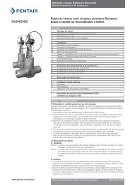
<strong>High</strong> Pressure Forged Gate ValvesCalculation of Pressure Drop IINotesA Gate Valve with connecting inlet d1=dPort DiameterB,C Gate Valve with connecting inlet d1> dPort DiameterD Swing Check ValveE Angle Globe Valve Cast SteelF Angle Globe Valve Forged SteelG Straight Globe Valve Cast SteelH Straight Globe Valve Forged SteelK Y-Type Forged SteelFEHGKDζ ZetaAConnecting inlet diameter/port diameter d1/dNotesΔp (bar) = Pressure DropW (m/s) = Velocity(kg/ m 3 ) = Specific Gravity of liquidζ (-) = Zeta, resistance valuev (m 3 /kg) = Specific Volume of steamw (m/s) = VelocityG (kg/s) = FlowF (m 2 ) = Flow area∝∝Fluid ΔP = ζ x _____ x w 2 x 10 -521Steam ΔP = ζ x ___ x w 2 x 10 -52vW = ______ GF x∝W = ______ G x VFT(°C)∝Kg[ ___ ]m 3P[bar]Pentair reserves <strong>the</strong> right <strong>to</strong> change <strong>the</strong> contents without notice page 7
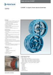
<strong>High</strong> Pressure Forged Gate ValvesDetails of <strong>the</strong> <strong>forged</strong> steel <strong>pressure</strong> seal constructionStandard CharacteristicsWedgeWe have designed a new tee-head connection of <strong>the</strong> wedge. The wedge is now closed around <strong>the</strong>stem. Flexible split wedge is standard on Forged Valves and wedge’s guide is integral <strong>to</strong> <strong>the</strong> bodywithout any welding. During <strong>the</strong> stroke, <strong>the</strong> contact area between wedge and seat rings is wide.The design gives <strong>the</strong> following coefficients or friction for <strong>to</strong>rque calculation:• µ = 0.4 for wedge or parallel slides• µ = 0.15 for lubricated stem threadsWedgeContact areaSeatringSeatrings are welded inYokeStandard <strong>Sempell</strong> materials for yoke nut are ductile iron Ni-Resist D2 or Bronze B148 Gr.B.All yoke nuts are <strong>provide</strong>d with two needle bearings. Every yoke has a lubrication nipple.The yokes are equipped with a connecting flange on <strong>the</strong> <strong>to</strong>p, ready <strong>to</strong> assemble gear, mo<strong>to</strong>rdevices and o<strong>the</strong>r accessories.BonnetAdvanced Pressure Seal design is such that <strong>the</strong> bonnet is easy <strong>to</strong> be dismantled.Important : <strong>the</strong> bonnet must not be dropped in<strong>to</strong> <strong>the</strong> body cavity<strong>the</strong> segment ring is kept in <strong>the</strong> right position by <strong>the</strong> safety ring<strong>High</strong> tightness is achieved with pure graphite gasket rings, covered with a layer of 18.8 on bothsides.PackingThe new design of packing ensures high tightness with pure graphite pressed rings (min.density1.8 g/cm 3 ) with a ground ring for guiding.The packing chamber is shorter and narrower because <strong>the</strong> sealing effectiveness improves as overallpacking dimensions decrease. The chamber wall surface roughness is Rz < 5 µm and <strong>the</strong> surfaceroughness of <strong>the</strong> stem running through <strong>the</strong> stuffing box is Rz < 1.6 µm.The new design of pure graphite packing also allows vacuum service and protection againstfugitive emissions.Position Indica<strong>to</strong>rThe mechanical indica<strong>to</strong>r for open and closed position is standard on <strong>High</strong> Pressure Forged Valves.Pentair reserves <strong>the</strong> right <strong>to</strong> change <strong>the</strong> contents without notice page 8
<strong>High</strong> Pressure Forged Gate ValvesSafety DevicesImportant noteStandard <strong>Sempell</strong> <strong>pressure</strong> seal <strong>valves</strong> will not be furnished with safety device, unless required by<strong>the</strong> user.It is <strong>the</strong> responsibility of <strong>the</strong> purchaser <strong>to</strong> require <strong>to</strong> supply a safety device, depending on <strong>the</strong>function on <strong>the</strong> gate valve.Pressure of trapped water (bar)Percentage volume of water (%)Body cavityA gate valve in close position can retain a volume of water in <strong>the</strong> body cavity. An increase of <strong>the</strong>temperature will consequently increase <strong>the</strong> <strong>pressure</strong> in <strong>the</strong> body cavity with <strong>the</strong> risk of relevantdamages of <strong>the</strong> body and <strong>the</strong> bonnet. To eliminate this risk, <strong>Sempell</strong> offers you 4 possible<strong>solution</strong>s.Accessories1. Solution: Acc. 5Hole in <strong>the</strong> seat ring2. Solution: Acc. 6Hole in <strong>the</strong> wedge3. Solution: Acc. 73 nozzles with capsIn <strong>the</strong> plant <strong>the</strong> client can connect 2 of <strong>the</strong>m dependingon <strong>the</strong> flow direction4. Solution: Acc. 8With over-<strong>pressure</strong> protection for two directionsOpen interlockedPentair reserves <strong>the</strong> right <strong>to</strong> change <strong>the</strong> contents without notice page 9
<strong>High</strong> Pressure Forged Gate ValvesAccessories (optional)Acc. 9 - Nozzle Acc. 10 - Nozzle with cap Acc. 11 - Nozzle/Connection of drainAcc. 12 - By-passAcc. 13 - Limit switch for open orclosed positionAcc. 14 - Limit switch for open andclosed positionAcc. 15 - Locking deviceAcc. 16 - Floor stands with extensionstems below <strong>the</strong> valveAcc. 17 - Floor stands with extensionstems above <strong>the</strong> valvePentair reserves <strong>the</strong> right <strong>to</strong> change <strong>the</strong> contents without notice page 10
<strong>High</strong> Pressure Forged Gate ValvesMaterial SpecificationsFigure GA251.6012 – GA251.6015Fig. Class PN6012 900 9(160)6013 1500 15(250)6014 2500 25(500)6015 4500 45(720)Material <strong>to</strong> API 600Body Wedgeseat seating Backsurface surface Stem seatTrim part part part partno no 29.1 no 28.1 no 20 no 211 13%Cr 13 % Cr 13 % Cr 13% Cr5 Stellite Stellite 13% Cr 13% Cr17% Cr*8 Stellite 13 % Cr 13% Cr 13% Cr12 F 316 / F 316/ F 316 or F 316Stellite Stellite 17 4 PHbelow 450 °C* Over 450°CMaterial Specifications11 12 13 14 15 16 17 18Item -20°C - 425°C -46°C - 425°C 200°C - 540°C 250°C - 550°C 400°C - 575°C 500°C - 650°C 38°C - 450°C 130°C - 650°CA105 1.0460 LF2 TT5 F1 15Mo3 F12 13CrMo44 F22 10CrMo910 F91 P91 15CuNiMoNb5 F316 X6CrNiNb18101.0411 1.5415 1.7335 1.7380 1.4903 1.6368 1.45501 Body A105 1.0460 LF2 TT5 F1 15Mo3 F12 13CrMo44 F22 10CrMo910 F91 15CuNiMoNb5 F316 X6CrNiNb18102 Bonnet A105 1.0460 LF2 TT5 F1 15Mo3 F12 13CrMo44 F22 10CrMo910 F91 15CuNiMoNb5 F316 X6CrNiNb18103 Yoke A105 A105 A105 A105 A105 A105 A105 A1054 Safety Ring A105 A105 A105 A105 A105 A105 A105 A1055 Segment Ring A105 1.0460 LF2 TT5 F1 15Mo3 F12 13CrMo44 F22 10CrMo910 F91 15CuNiMoNb5 F316 X6CrNiNb18106 Ring A105 1.0460 LF2 TT5 F1 15Mo3 F12 13CrMo44 F22 10CrMo910 F91 15CuNiMoNb5 F316 X6CrNiNb18107 Gasket Pure Graphite Pure Graphite Pure Graphite Pure Graphite Pure Graphite Pure Graphite Pure Graphite Pure Graphite8 Bolts A193 B7 A193 B7 A193 B7 A193 B7 A193 B7 A193 B7 A193 B7 A193 B79 Nuts A194 2H A194 2H A194 2H A194 2H A194 2H A194 2H A194 2H A194 2H10 Nuts A194 2H A194 2H A194 2H A194 2H A194 2H A194 2H A194 2H A194 2H11 Bolts A193 B7 A193 B7 A193 B7 A193 B7 A193 B7 A193 B7 A193 B7 A193 B713 Ground Ring 17Cr 1.4122 17Cr 1.4122 17Cr 1.4122 17Cr 1.4122 17Cr 1.4122 17Cr 1.4122 17Cr 1.4122 17Cr 1.412214 Packing Pure Graphite Pure Graphite Pure Graphite Pure Graphite Pure Graphite Pure Graphite Pure Graphite Pure Graphite15 Gland F6 F6 F6 F6 F6 F6 F6 F616 Gland Flange A105 A105 A105 A105 A105 A105 A105 A10517 Gland Nuts A194 2H A194 2H A194 2H A194 2H A194 2H A194 2H A194 2H A194.818 Bolts A193 B7 A193 B7 A193 B7 A193 B8 A193 B8 A193 B8 A193 B7 A193 B819 Cut Ring Pure Graphite Pure Graphite Pure Graphite Pure Graphite Pure Graphite Pure Graphite Pure Graphite Pure Graphite21 Yoke Nut Bronze B 148 Bronze B 148 Bronze B 148 Bronze B 148 Bronze B 148 Bronze B 148 Bronze B 148 Bronze B 148gr.B or gr.B or gr.B or gr.B or gr.B or gr.B or gr.B or gr.B orNi-resist D2 Ni-resist D2 Ni-resist D2 Ni-resist D2 Ni-resist D2 Ni-resist D2 Ni-resist D2 Ni-resist D222 Bearings Steel Steel Steel Steel Steel Steel Steel Steel25 Indica<strong>to</strong>r A105 A105 A105 A105 A105 A105 A105 F31628 Wedge A105 1.0460 LF2 TT5 F1 15Mo3 F12 13CrMo44 F22 10CrMo910 F91 15CuNiMoNb5 F316 X6CrNiNb181029 Seat Ring A105 1.0460 LF2 TT5 F1 15Mo3 F12 13CrMo44 F22 10CrMo910 F91 15CuNiMoNb5 F316 X6CrNiNb181032 O-ring Vi<strong>to</strong>n Vi<strong>to</strong>n Vi<strong>to</strong>n Vi<strong>to</strong>n Vi<strong>to</strong>n Vi<strong>to</strong>n Vi<strong>to</strong>n Vi<strong>to</strong>n33 Handwheel Steel Steel Steel Steel Steel Steel Steel Steel37 Distance wedge F6 F6 F6 F6 F6 F6 F6 F6Pentair reserves <strong>the</strong> right <strong>to</strong> change <strong>the</strong> contents without notice page 11
<strong>High</strong> Pressure Forged Gate ValvesASME Class 900PipeconnectionL B.W. ends L2 RTJ flanged ends <strong>to</strong> ASME B16.10L1 B.W. ends <strong>to</strong> ASME B16.10ASME Cl. 900/Pressure Rating 09 (PN 160) - fig. GA251.6012DN (mm) DN (in.) L L 1 L 2 H V Pipe Conn. Weight (kg)d 1N x d N d 1N x d NOD max ID min BW BW2 FL50 265 x 50 2 1 /2 x 265 2 1 /280 x 65 3 x 2 1 /280 3100 x 80 4 x 3100 4125 x 100 5 x 4125 5150 x 125 6 x 5150 6200 x 150 8 x 6175 7200 x 175 8 x 7200 8250 x 200 10 x 8250 10300 x 250 12 x 10300 12350 x 300 14 x 12350 14400 x 350 16 x 14400 16450 x 400 18 x 16450 18500 x 450 20 x 18500 20600 x 500 24 x 20216 216 - 515 300 95 55 45 45 65216 254 384 515 300 95 55 45 45 65305 305 384 590 400 135 72 70 70 85325 356 460 700 500 170 96 105 100 145375 432 R 770 450 190 121 162 R R450 508 613 850 450 225 146 220 235 275525 660 R 950 500 280 167 320 R 420575 660 740 1050 500 280 188 390 415 560650 787 841 1460 750 332 236 695 735 810750 914 968 1650 750 365 280 1000 1160 1200850 991 1038 1880 850 420 306 1280 1280 1500950 1092 1140 2100 850 475 342 1700 1700 19501050 R R 2320 960 525 380 R R R1100 R R R R 580 425 R R RNotes1. All dimensions are in mm.2. BW: weight for buttweld ends type (<strong>Sempell</strong>standard).3. BW2: weight for buttweld ASME ends type.4. FL: weight for flanged ends type.5. R: available on request.6. The dimensions in bold correspond <strong>to</strong> ourstandard dimensions for 1-piece body.GA251.6012 8”(200)6”(150) 14 5 BWLButt weld ends <strong>to</strong> <strong>Sempell</strong> StandardTrim materialMaterial SpecificationNominal Size inches (mm)Connection pipe ends inches (mm)ASME Class 900, press rating 09 (PN 160)Gate Valve<strong>High</strong> Pressure Forged ValvePentair reserves <strong>the</strong> right <strong>to</strong> change <strong>the</strong> contents without notice page 12
<strong>High</strong> Pressure Forged Gate ValvesASME Class 1500PipeconnectionL B.W. ends L2 RTJ flanged ends <strong>to</strong> ASME B16.10L1 B.W. ends <strong>to</strong> ASME B16.10Notes1. All dimensions are in mm.2. BW: weight for buttweld ends type (<strong>Sempell</strong>standard).3. BW2: weight for buttweld ASME ends type.4. FL: weight for flanged ends type.5. R: available on request.6. BGR: bevel gear on request.7. The dimensions in bold correspond <strong>to</strong> ourstandard dimensions for 1-piece body.ASME Cl. 1500/Pressure Rating 15 (PN 250) - fig. GA251.6013DN (mm) DN (in.) L L 1 L 2 H V Pipe Conn. Weight (kg)d 1N x d N d 1N x d NOD max ID min BW BW2 FL50 265 x 50 2 1 /2 x 265 2 1 /280 x 65 3 x 21/280 3100 x 80 4 x 3100 4125 x 100 5 x 4125 5150 x 125 6 x 5150 6200 x 150 8 x 6175 7200 x 175 8 x 7200 8250 x 200 10 x 8250 10300 x 250 12 x 10300 12350 x 300 14 x 12350 14400 x 350 16 x 14400 16450 x 400 18 x 16450 18500 x 450 20 x 18500 20600 x 500 24 x 20216 216 371 515 300 95 52 45 45 60216 254 422 515 300 95 52 45 45 82305 305 473 590 400 135 68 70 70 115350 406 549 700 500 170 92 135 150 170400 559 R 770 500 190 118 220 R R475 559 711 850 750 225 135 250 280 400600 711 R 950 750 280 155 380 420 630625 711 841 1050 750 280 175 480 520 795725 864 1000 1500 BGR 332 215 890 945 1200800 991 1146 1680 BGR 365 255 1170 1298 1800950 1067 1276 1900 BGR 420 280 1330 1420 23001000 1194 1407 2200 BGR 475 322 1850 1990 32501050 1346 1559 2500 BGR 525 352 R R R1100 1473 R R R 580 380 R R RGA251.6013 8”(200)6”(150) 14 5 BWLButt weld ends <strong>to</strong> <strong>Sempell</strong> StandardTrim materialMaterial SpecificationNominal Size inches (mm)Connection pipe ends inches (mm)ASME Class 1500,press rating 15 (PN 250)Gate Valve<strong>High</strong> Pressure Forged ValvesPentair reserves <strong>the</strong> right <strong>to</strong> change <strong>the</strong> contents without notice page 13
<strong>High</strong> Pressure Forged Gate ValvesASME Class 2500PipeconnectionL B.W. ends L2 RTJ flanged ends <strong>to</strong> ASME B16.10L1 B.W. ends <strong>to</strong> ASME B16.10ASME Cl. 2500/Pressure Rating 25 (PN 500) - Fig. GA251.6014DN (mm) DN (in.) L L 1 L 2 H V Pipe Conn. Weight (kg)d 1N x d N d 1N x d NOD max ID min BW BW2 FL50 265 x 50 2 1 /2 x 265 2 1 /280 x 65 3 x 21/280 3100 x 80 4 x 3100 4125 x 100 5 x 4125 5150 x 125 6 x 5150 6200 x 150 8 x 6175 7200 x 175 8 x 7200 8250 x 200 10 x 8250 10300 x 250 12 x 10300 12350 x 300 14 x 12350 14400 x 350 16 x 14400 16450 x 400 18 x 16450 18500 x 450 20 x 18500 20600 x 500 24 x 20216 279.4 454 515 300 95 48 45 45 80216 330 514 515 300 95 48 45 45 160350 368 584 590 400 135 65 110 125 168425 457 683 700 500 170 85 170 185 260450 533 R 770 500 190 102 280 R R559 610 927 850 750 225 122 370 405 670711 762 R 970 750 280 144 450 550 890725 762 1038 1070 750 280 160 750 795 1480800 914 1292 1550 BGR 332 198 1120 1245 2000900 1041 1445 1730 BGR 365 236 1500 1600 30001000 1118 R 1980 BGR 420 260 1850 1970 R1100 1245 R 2230 BGR 475 310 2200 2450 RR R R 2600 BGR 525 334 R R RR R R R R 580 365 R R RNotes1. All dimensions are in mm.2. BW: weight for buttweld ends type (<strong>Sempell</strong>standard).3. BW2: weight for buttweld ASME ends type.4. FL: weight for flanged ends type.5. R: available on request.6. BGR: bevel gear on request.7. The dimensions in bold correspond <strong>to</strong> ourstandard dimensions for 1-piece body.GA251.6014 8”(200) 6”(150) 14 5 BWLButt weld ends <strong>to</strong> <strong>Sempell</strong> StandardTrim materialMaterial SpecificationNominal Size inches (mm)Connection pipe ends inches (mm)ASME Class 2500, press rating 25 (PN 500)Gate Valve<strong>High</strong> Pressure Forged ValvePentair reserves <strong>the</strong> right <strong>to</strong> change <strong>the</strong> contents without notice page 14
<strong>High</strong> Pressure Forged Gate ValvesGear Operated ValvesGear Type 300 600 1100 1101 2300 2301 3800 6000 9000 16000Connection F10 F14 F16 F25 F25 F25 F30 F35 F35 F40Gear ratio 1:4,5 1:4,5 1:4,5 1:15,75 1:4,5 1:20,25 1:20,25 1:36 1:40 1:105Fig. GA251.6012 DNFig. GA251.6013 DNFig. GA251.6014 DNFig. GA251.6015 DN- 2”- 5” 6” - - 8”- 10” 12” 14”- 20”- 2”- 5” 6” - - 8”- 10” 12” 14”- 20” 24”- 2”- 4” 6” - - 7”- 8” 10” 12” 18”- 20”- 3” - - 6” 8”Dimensions in mmAA1BCVWeight (Kg)180 200 250 315 305 370 420 510 605 770216 253 258 258 338 338 338 374 419 47087 114 141 141 164 164 178 238 243 30356 74 92 92 102 102 115 150 155 215300 500 800 800 800 500 800 800 800 80010 18 30 40 59 79 115 155 210 320Acc. 1 - Type Bevel GearAcc. 2 - Type Spur GearMo<strong>to</strong>r Operated ValvesAccessoriesAll <strong>Sempell</strong> “Pressure Seal” Valves can be equipped with electrical, pneumatic or hydraulic actua<strong>to</strong>rs. Cus<strong>to</strong>mers are asked, when ordering, <strong>to</strong> specify<strong>the</strong> following requirements that may enable us <strong>to</strong> supply <strong>the</strong> correct actua<strong>to</strong>rs:1 Medium 7 Voltage and frequency, <strong>pressure</strong> of operating fluid (air or hydraulic)2 Working temperature 8 Closing time3 Working <strong>pressure</strong> 9 Number and type of any auxiliary position indica<strong>to</strong>rs (Limit switch)4 Differential <strong>pressure</strong> across <strong>the</strong> valve 10 Special classes of insulation5 Nominal diameter of <strong>the</strong> valve 11 Waterproof or explosion proof6 Type of actua<strong>to</strong>rAcc. 3 Acc. 4Pentair reserves <strong>the</strong> right <strong>to</strong> change <strong>the</strong> contents without notice page 15
<strong>High</strong> Pressure Forged Gate ValvesAccessoriesAccessories1 - Bevel gear handwheel page 152 - Spur gear handwheel page 153 - Actua<strong>to</strong>r page 154 - Bevel gear and actua<strong>to</strong>r page 155 - Safety device, <strong>solution</strong> 1, hole in <strong>the</strong> seat ring page 96 - Safety device, <strong>solution</strong> 2, hole in <strong>the</strong> wedge page 97 - Safety device, <strong>solution</strong> 3, nozzles with caps page 98 - Safety device, <strong>solution</strong> 4, over <strong>pressure</strong> protection for two directions page 99 - Nozzle page 1010 - Nozzle with cap page 1011 - Nozzle, Connection of drain page 1012 - By-pass page 1013 - Limit switch for open or closed position page 1014 - Limit switch for open and closed position page 1015 - Locking device page 1016 - Floor stands with extension stems below <strong>the</strong> valve page 1017 - Floor stands with extension stems above <strong>the</strong> valve page 10How <strong>to</strong> orderI II III IV V VI VII VIII IX XTo ASME GA251.6013 8” 6” 14 5 BW L 5To ISO GA251.6013 200 150 14 5 BW L 5I6 = <strong>High</strong> Pressure Forged ValveII Type of Valve 01 Gate ValveIIIIVVClass2 900 - Pressure Rating 09 (PN 160)3 1500 - Pressure Rating 15 (PN 250)4 2500 - Pressure Rating 25 (PN 500)5 4500 - Pressure Rating 45 (PN 720)Connection pipe ends inches (mm)Nominal size inches (mm)VI Material specification, please refer <strong>to</strong> page 11VIIType of trim, please refer <strong>to</strong> separate page for every valve type according <strong>to</strong> point VIVIII BW Butt weld endsFR Flanges RTJBWS Butt weld ends SpecialIX L End <strong>to</strong> connections BW <strong>to</strong> <strong>Sempell</strong> standardL1 End <strong>to</strong> connections BW <strong>to</strong> ASME B16.10L2 End <strong>to</strong> connections Flanged RTJ <strong>to</strong> ASME B16.10S1 Lengths of angle <strong>valves</strong>XAccessories number, please refer abovePentair reserves <strong>the</strong> right <strong>to</strong> change <strong>the</strong> contents without notice page 16