
You also want an ePaper? Increase the reach of your titles
YUMPU automatically turns print PDFs into web optimized ePapers that Google loves.
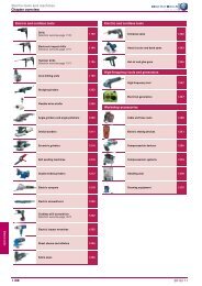
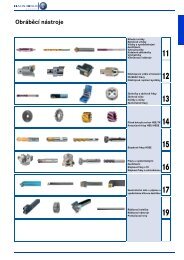
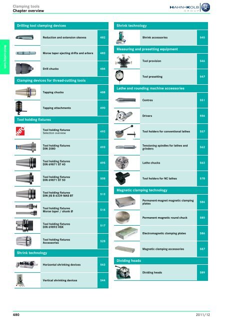
<strong>Clamping</strong> toolsChapter overviewContinued next pageContinued next pageDrilling tool clamping devicesShrink technologyReduction and extension sleeves 482Shrink accessories 545Metal-cutting toolsMorse taper ejecting drifts and arbors 483Drill chucks 484Measuring and presetting equipmentTool provision 546<strong>Clamping</strong> devices for thread-cutting toolsTapping chucks 488Tool presetting 547Lathe and rounding machine accessoriesCentres 551Tapping attachments 490Tool holding fixturesDrivers 556Tool holding fixturesSelection overview492Tool holders for conventional lathes 557Tool holding fixturesDIN 2080493Tensioning spindles for lathes andgrinders562Tool holding fixturesDIN 69871 ST 40495Lathe chucks 563Tool holding fixturesDIN 69871 ST 50508Tool holders for NC lathes 578Tool holding fixturesDIN JIS B 6339 MAS BTTool holding fixturesMorse taper / shank Ø513514Magnetic clamping technologyPermanent-magnet magnetic clampingplates584Permanent magnetic round chuck 585Tool holding fixturesDIN 69893 HSK517Electromagnetic clamping plates 586Tool holding fixturesAccessories528Shrink technologyMagnetic clamping accessories 587Horizontal shrinking devices 543Dividing headsDividing heads 589Vertical shrinking devices 544480 2011/12
<strong>Clamping</strong> toolsChapter overviewContinued next pageContinued next pageTool guidingsHydraulic clamping technologySlide guideways 592Hydraulic tools 643Conventional workpiece clampingMechanical clamping elements 594Hydraulic presses 649Metal-cutting toolsQuick-action clamps 607Positioning elementsParallel supports 613Mounting devices 615Workpiece clampingWorkpiece clampingSelection overview617Workpiece stops 618Precision vices 619Drilling machine vices 620Machine vices 621High-pressure machine vices 6245-axis machine vices 631Multiple clamping vices 638Multi-function clamping vices 6410-point clamping systems 6422011/12481
Drilling tool clamping devicesReduction and extension sleevesContinued next pageReduction sleeves DIN 2185Execution: male and female taper according to DIN 228, hardened, male and female taper ground.Application: for tools with morse taper.Metal-cutting toolsMale/female taper MT 1/0 2/1 3/1 3/2 4/1 4/2 4/3 5/2 5/3 5/4 6/5Overall length mm 80 92 99 112 124 124 140 156 156 171 21821102 Ident. No. 010 021 031 032 041 042 043 052 053 054 065Unit price E O. R. O. R. O. R. O. R. O. R. O. R. O. R. O. R. O. R. O. R. O. R.Prod. Gr. 207Continued next pageExtensionsExecution: male and female taper according to DIN 228, female taper ground.Application: for tools with morse taper, such as drills and reamers.DL2L1Male/female taper MT 1/1 2/2Total length L 1 mm 200 250 300 350 400 200 250 300 350 400 450 500 600Length L2 mm 138 188 238 288 338 125 175 225 275 325 375 425 525Cylinder Ø mm 20 20 20 20 20 25 25 25 25 25 25 25 2521107 Ident. No. 120 125 130 135 140 220 225 230 235 240 245 250 260Unit price E O. R. O. R. O. R. O. R. O. R. O. R. O. R. O. R. O. R. O. R. O. R. O. R. O. R.Male/female taper MT 3/3 4/4Total length L 1 mm 250 300 350 400 450 500 600 300 350 400 450 500 600Length L 2 mm 156 206 256 306 356 406 506 182,5 232,5 282,5 332,5 382,5 482,5Cylinder Ø mm 32 32 32 32 32 32 32 40 40 40 40 40 4021107 Ident. No. 325 330 335 340 345 350 360 430 435 440 445 450 460Unit price E O. R. O. R. O. R. O. R. O. R. O. R. O. R. O. R. O. R. O. R. O. R. O. R. O. R.Prod. Gr. 207Continued next pageExtensionsExecution: male and female taper according to DIN 228.No. 21114 external taper ground, structural dimensions similar to DIN 2187No. 21115 ground male and female taper, DIN 2187, hardenedApplication: for tools with morse taper.DL2L1Male/female taper MT 1/1 1/2 2/1 2/2 2/3 3/1 3/2 3/3 3/4 4/3 4/4 4/5 5/4 5/5Total length L 1 mm 145 160 160 175 196 175 194 215 240 240 265 300 300 300Length L 2 mm 83 98 85 100 121 81 100 121 146 122,5 147,5 182,5 150,5 182,5Cylinder Ø mm 20 30 20 30 36 20 30 36 48 36 48 63 48 63Ident. No. 011 012 021 022 023 031 032 033 034 043 044 045 054 05521114 Unit price E O. R. O. R. O. R. O. R. O. R. O. R. O. R. O. R. O. R. O. R. O. R. O. R. O. R. O. R.21115 Unit price E O. R. O. R. O. R. O. R. O. R. O. R. O. R. O. R. O. R. O. R. O. R. O. R. O. R. O. R.h Extension sleeves available in special lengths on request. Prod. Gr. 207Continued next pageSplit taper sleeves DIN 6329Application: for holding twist drills with fit X8 and other tools with straight shank and flat tang.Not suitable for milling.A clamping sleeve is required for each shank Ø.DdMKMorse taper MT 1 2Shank Ø d mm 3 3,5 4 4,5 5 5,5 6 6,5 7 8 6 721150 Ident. No. 103 106 109 112 115 118 121 124 127 133 203 209Unit price E O. R. O. R. O. R. O. R. O. R. O. R. O. R. O. R. O. R. O. R. O. R. O. R.Morse taper MT 2 3Shank Ø d mm 8 8,5 9 9,5 10 10,5 11 12 12 12,5 14 1621150 Ident. No. 215 218 221 224 227 230 233 239 327 330 339 351Unit price E O. R. O. R. O. R. O. R. O. R. O. R. O. R. O. R. O. R. O. R. O. R. O. R.h Other dimensions on request (specially manufactured). Prod. Gr. 207482 2011/12
Drilling tool clamping devicesMorse taper ejecting drifts and arboursContinued next pageSplit taper sleeves DIN 6328Application: for holding taps and twist drills, fit h8, with straight shank and square.Not suitable for milling.A clamping sleeve is required for each shank Ø.DdMKMorse taper MT 1 2 3Shank Ø d mm 4,5 6 7 8 6 7 8 9 10 12 14 16Square mm 3,4 4,9 5,5 6,2 4,9 5,5 6,2 7 8 9 11 1221155 Ident. No. 103 109 112 115 203 206 209 212 215 218 303 306Unit price E O. R. O. R. O. R. O. R. O. R. O. R. O. R. O. R. O. R. O. R. O. R. O. R.h Other dimensions on request (specially manufactured). Prod. Gr. 207Metal-cutting toolsContinued next pageMorse taper ejecting drifts (mechanical) DIN 317Execution: made of special steel, tempered and bronzed.Application: for taper shanks conforming to DIN 228 with flat tang.Morse taper MT 0 1 and 2 3 4 5 and 621160 Ident. No. 005 010 030 040 050Unit price E O. R. O. R. O. R. O. R. O. R.Prod. Gr. 207Continued next pageMorse taper ejecting drifts (mechanical)Execution: made of special steel hardened, tempered and bronzed blade size 1-3 with finger protection.Application: semi-automatic, for one-hand operation, for taper shanks according to DIN 228 with flat tang;by activating the lever the tool taper is released in the spindle without impact.Morse taper MT 1-3 4-621165 Ident. No. 010 020Unit price E O. R. O. R.Prod. Gr. 260Continued next pageArbourswith morse taper, for drill chuckExecution: hardened and ground.Application: for holding drill chucks.DIN 238-1Drill chuck B 10 B 12 B 16 B 18 B 22Taper shank MT 1 2 1 2 3 1 2 3 4 1 2 3 4 5 2 3 4Smallest Ø of taper B mm 9,4 9,4 11,1 11,1 11,1 14,5 14,5 14,5 14,5 16,2 16,2 16,2 16,2 16,2 19,8 19,8 19,8Largest Ø of taper B mm 10,095 10,095 12,06 12,06 12,06 15,733 15,733 15,733 15,733 17,780 17,780 17,780 17,780 17,780 21,793 21,793 21,79321269 Ident. No. 101 102 121 122 123 161 162 163 164 181 182 183 184 185 222 223 224Unit price E O. R. O. R. O. R. O. R. O. R. O. R. O. R. O. R. O. R. O. R. O. R. O. R. O. R. O. R. O. R. O. R. O. R.h Drill chuck holders with steep taper see No. 23272 page 493. Prod. Gr. 207Continued next pageArbours in precision designwith straight shank, for drill chuckExecution: hardened and ground, concentricity tolerance ≤ 2 μm.Application: for holding drill chucks.Drill chuck B 6 B 10 B 12 B 16Shaft Ø mm 6 8 10 10 16Shank length mm 35 35 50 50 50Smallest Ø of taper B mm 5,85 9,4 9,4 11,1 14,5Largest Ø of taper B mm 6,35 10,095 10,095 12,06 15,73321270 Ident. No. 305 310 320 330 340Unit price E O. R. O. R. O. R. O. R. O. R.h Other dimensions available on request. Prod. Gr. 2092011/12483
Drilling tool clamping devicesDrill chucksContinued next pageArbours in precision designwith morse taperExecution: Hardened and ground, with concentricity tolerance ≤ 2 μm.Application: to hold drill chucks art. no. 21311, page 487.sim. DIN 238-1Metal-cutting toolsArbours, drill chuck B 6 B 10 B 12 B 16 B 18**Taper shank MT 1 1 2 1 2 3 2 3 4 2 3 421313 Pin spindle Ident. No. 091 101 102 121 122 123 162 163 164 182 183 184Unit price E O. R. O. R. O. R. O. R. O. R. O. R. O. R. O. R. O. R. O. R. O. R. O. R.** Shortened by 7 mm, differing from DIN 238-1. Prod. Gr. 209Continued next pageRelease fork ADGApplication: for releasing the drill chuck from the arbour. It prevents damage, which can occur if unsuitablemethods are used.abcedFor taper B 6 B 10/12 B 16/18Dimensions a/b/c mm 120/20/7 170/30/11 210/40/16,7Dimensions d/e mm -/8 13/10 18,7/1221271 Ident. No. 006 010 016Unit price E O. R. O. R. O. R.Prod. Gr. 209Continued next pageDrill chucks with taper pin adaptorfor right- and left-hand rotation, with toothed rim and keyExecution: head with keyholes and jaws hardened.No. 21290 RÖHM Prima heavy-duty type, with female taper according to DIN 238.No. 21291 RÖHM Prima industrial design for manually controlled machines, with female taperaccording to DIN 238.No. 21293 ORION industrial design for manually controlled machines, with female taper according toDIN 238.No. 21294 spare keyDNo. 21290 -21291 No. 21293Taper pin adaptor No. 21294<strong>Clamping</strong> width mm 0,5-6,5 0,5-8 0,8-10 1-10 1-13 1-16 1,5-13 3-16 5-20Female taper to DIN 238 B 10 B 12 B 10 B 12 B 12 B 12 B 16 B 16 B 16 B 18 B 12 B 16 B 16 B 18 B 22External Ø mm 29,5 29,5 29,5 34,5 33,5 34,5 42,4 42,8 52 56,5 42,8 42,4 50 50 65Pilot Ø (key) D mm 4 4 4 6 6 6 6 6 8 8 6 6 8 8 9No. of teeth (key) 10 10 10 12 12 12 12 12 12 12 12 12 12 12 1421290 RÖHM Ident. No. – 030 – 040 – – – 050 080 170 – – – – 200Unit price E – O. R. – O. R. – – – O. R. O. R. O. R. – – – – O. R.21291 RÖHM Ident. No. 010 – 020 – – 030 – – – – 040 – 050 – –Unit price E O. R. – O. R. – – O. R. – – – – O. R. – O. R. – –21293 ORION Ident. No. – – – – 010 – 020 – – – – 030 040 042 –Unit price E – – – – O. R. – O. R. – – – – O. R. O. R. O. R. –21294 Replacement key Ident. No. 010 020 030 020 030 040Unit price E O. R. O. R. O. R. O. R. O. R. O. R.h Arbours see No. 21269 page 483. No. 21290, 21291, 21294 = Prod. Gr. 201No. 21293 = Prod. Gr. 207484 2011/12
Drilling tool clamping devicesDrill chucksContinued next pageDrill chucks with thread adaptorfor right-hand rotation, with toothed rim and keyExecution: head with keyholes and jaws hardened.No. 21292 RÖHM Prima industrial design for manually controlled machines, with inside thread, only forright-hand rotation.No. 21293 ORION industrial design for manually controlled machines, with inside thread, only for righthandrotation.No. 21294 spare keyDIN 6349Metal-cutting toolsthread adapter No. 21294DNo. 21292 No. 21293<strong>Clamping</strong> width mm 0,5-6,5 0,5-8 0,8-10 1,5-13 3-16Thread UNF-3 B 3/ 8"x24 3/ 8"x24 3/ 8"x24 3/ 8"x24 1/ 2"x20 1/ 2"x20 3/ 8"x24 1/ 2"x20 1/ 2"x20 1/ 2"x20 5/ 8" x 16*External Ø mm 29,5 29,5 33,3 34,5 33,3 34,5 42,8 42,4 42,8 50 50Pilot Ø (key) D mm 4 4 6 6 6 6 6 6 6 8 8No. of teeth (key) 10 10 12 12 12 12 12 12 12 12 1221292 RÖHM Ident. No. 035 041 – 045 – 051 055 – 060 185 171Unit price E O. R. O. R. – O. R. – O. R. O. R. – O. R. O. R. O. R.21293 ORION Ident. No. – – 110 – 112 – – 130 – – –Unit price E – – O. R. – O. R. – – O. R. – – –21294 Replacement key Ident. No. 010 020 030Unit price E O. R. O. R. O. R.* Thread UN-3 B. No. 21292, 21294 = Prod. Gr. 201No. 21293 = Prod. Gr. 207Continued next pageDrill chucks with taper pin adaptorExecution: for right-hand rotation, self-locking, all parts replaceable.No. 21300 RÖHM Prima heavy-duty type, with female taper according to DIN 238No. 21301 RÖHM Prima industrial design for manually controlled machines, with female taperaccording to DIN 238No. 21304 ORION industrial design for manually controlled machines, with female taper according toDIN 238Taperholder<strong>Clamping</strong> width ** mm 0-4 0-6,5 0-8 0-10 1-13 3-16Female taper to DINB 10 B 10 B 12 B 10 B 12 B 12 B 16 B 12 B 16 B 16 B 18 B 18*238Outer Ø No. 21300 mm 28 35 35 35,8 35,8 40,2 40,2 – 46 51 – 5121300 RÖHM Ident. No. 010 020 030 040 050 070 080 – 090 100 – 110Unit price E O. R. O. R. O. R. O. R. O. R. O. R. O. R. – O. R. O. R. – O. R.Outer Ø No. 21301 mm – – – 32 32 35,8 – 40,2 40,2 46 – 4621301 RÖHM Ident. No. – – – 040 050 060 – 085 090 100 – 110Unit price E – – – (O. R.) O. R. O. R. – O. R. O. R. O. R. – O. R.Outer Ø No. 21300 mm – – – – 32 36 42,5 40,2 40 46 46 –21304 ORION Ident. No. – – – – 010 020 022 030 032 040 042 –Unit price E – – – – O. R. O. R. O. R. O. R. O. R. O. R. O. R. –* Shortened.** Ident. No. 060 = <strong>Clamping</strong> width 0.5-10 mm.h Arbours see No. 21269 page 483.No. 21300, No. 21301 = Prod. Gr. 201No. 21304 = Prod. Gr. 207Continued next pageDrill chucks Supra SExecution: for right-hand rotation, self-locking, all parts replaceable.Heavy-duty type for manually controlled machines, with inside thread.<strong>Clamping</strong> width mm 0-8 0,5-10 1-13 3-16Thread UNF-3 B 3/8" x24 1 /2" x20 3 /8" x24 1 /2"x20 3 /8" x24 1 /2" x20 1 /2" x20 5 /8"x16**External Ø mm 35 35 35,8 35,8 42,5 42,5 46 4621302 Ident. No. 040 050 070 080 085 090 100 110Unit price E O. R. O. R. O. R. O. R. O. R. O. R. O. R. O. R.Threadholder** Thread UN-3 B.h Arbours see No. 21269 page 483.Prod. Gr. 2012011/12485
Drilling tool clamping devicesDrill chucksContinued next pageDrill chucksself-locking, precision finish, for right-hand rotationExecution: for continuous use at minimum concentricity. All wear parts are case-hardened, ground andreplaceable. 100% concentricity check with different test pin diameters on different measuring plants, inanalogy to DIN ISO 10888.On chuck 0-1.5 mm a vernier for pre-adjustment is attached.<strong>Clamping</strong> width mm 0-1,5 0-3 0-5 0-6,5 0-8Female taper B 6 B 10 B 10 B 12 B 10 B 12 B 10 B 12External Ø mm 19 24 30 30 34 34 38 38Length open mm 35 44 56 56 61,5 61,5 69 69Length closed mm 37,5 47,5 61,5 61,5 68 68 77,5 77,5Tension force safety device – – – – – – – –21311 Drill chuck Ident. No. 015 030 053 050 063 065 083 080Unit price E O. R. O. R. O. R. O. R. O. R. O. R. (O. R.) O. R.Type SBFMetal-cutting tools21312 Spare jaws Ident. No. – – – – 065 – –Set price E – – – – O. R. – –<strong>Clamping</strong> width mm 0-10 1-13 3-16Female taper B 12 B 16 B 16 B 16 B 16 B 16 B 18 B 18External Ø mm 43 43 43 50 50 56 56 56Length open mm 80 80 80 90,5 90,5 95,5 95,5 95,5Length closed mm 91 91 91 103 103 109 109 109Tension force safety device – yes – yes – – yes –21311 Drill chuck Ident. No. 103 101* 100 131* 130 163 164* 160Unit price E O. R. O. R. O. R. O. R. O. R. O. R. O. R. O. R.Type NCBFIdent. No. 101,131, 164Taperholder21312 Spare jaws Ident. No. 100 130 160Set price E O. R. O. R. O. R.h For matching arbour see no. 21313 page 484.* Ident. No. 101, 131and 164 with locking jaws to prevent unintentional opening of the drillchuck in the event of the spindle stopping abruptly.Prod. Gr. 209Continued next pageDrill chucksExecution:No. 21314 ALBRECHT drill chuck SBF-plus shortened mode, self-locking, precision design, for right-handrotation. With this tool the drill chuck and attachment shank form one unit. This gives optimumstability and low concentricity tolerance. Particularly beneficial for machines with limitedworking area since shorter by 21 mm compared to the 2-part design with arbor/drill chuck.Ident. no. 035 and 235 diamond-coated clamping jaws, for improved holding of drill made ofsolid carbide and HSS with hardened shankIdent. no. 020-030 und 040-160 with diamond-coated clamping jaws on request.No. 21316 ORION drill chuck, self-locking, for right-hand rotation. Drill chuck and location taper are oneunit.ALBRECHTORION<strong>Clamping</strong> width Shank <strong>Clamping</strong> jawscoatingDimension L 1 21314 Dimension L 1 21316mm Ident. No. mm U. pr. E mm U. pr. EMT 2 – 020 85 O. R. 95,5 O. R.MT 3 – 030 85 O. R. 95,5 O. R.1-13MT 3 Diamond 035 85 (O. R.) – –MT 4 – 040 86,5 O. R. 98 O. R.1-13 Ø 16 – 160 79 O. R. 90,5 O. R.3-16MT 2 – 220 89 O. R. 100,5 O. R.MT 3 – 230 89 O. R. 100,5 O. R.MT 3 Diamond 235 89 (O. R.) – –MT 4 – 240 90 O. R. 102 O. R.l1MK31 221Dimensions comparison1 SBF and arbour (two-part)2 SBF-plus (single part)h Spare jaws see No. 21312 page 487. No. 21314 = Prod.-Gr. 209No. 21316 = Prod.-Gr. 2952011/12487
<strong>Clamping</strong> devices for thread-cutting toolsTapping chucksMetal-cutting toolsContinued next pageQuick-change tapping chucksshank design with steep taper DIN 69871 ANo. 21540 a quick-change tapping chuck type GSF-SK with even distribution of the pre-tension ofthe threaded cut (ball guide).Advantages: low maintenance expenditures with increased process safety in pre-cutting and cuttingphase.No. 21545 ORION quick-change tapping chuck with length balancing which is effective both under compressionand tensionApplication: for thread cutting and thread shaping on NC machines and processing centres. Duringreverse motion, the direction of rotation of the machine spindle needs to be changed.Number 21540 21545Size/inserts 1 2 2 1 1 2 2 1 2Power consumption ST 40 ST 40 ST 50 ST 40 ST 50 ST 40 ST 50 HSK 63 HSK 63For threadM3-M12 M8-M20 M8-M20 M3-M12 M3-M12 M6-M20 M6-M20 M3-M12 M6-M20Length compensation mm 7,5/7,5 10/10 10/10 9/9 9/9 15/15 15/15 7,5/7,5 10/10under pressure/tensionDimensions D mm 39 60 60 38 38 55 55 41 60Programming dimension mm 65 103 88 60 62 100 83 72 110AIdent. No. 610 630 640 610 620 630 640 650 660a Unit price E O. R. O. R. (O. R.) – – – – – –No. 21540No. 21545AADDORION Unit price E – – – O. R. O. R. O. R. O. R. O. R. (O. R.)h See required pull studs at No. 23690 page 541.Required quick-change inserts see No. 21560-21566 page 489.No. 21545 = Prod. Gr. 295No. 21540 = Prod. Gr. 225Continued next pageQuick-change tapping chucks type GSF-ZShank design with modular shank MS similar to DIN 1835 BExecution: quick-change tapping chuck type GSF-Z with even distribution of the pre-tension of thethreaded cut (ball guide).Advantages: low maintenance expenditures with increased process safety in pre-cutting and cuttingphase.Application: for thread cutting and thread shaping on NC machines and processing centres. Duringreverse motion, the direction of rotation of the machine spindle needs to be changed.Model 115 220Size 1 2For thread M3-M12 M8-M20Suitable quick-change inserts Size 1 2Length compensation under pressure/tension mm 7,5/7,5 10/10Dimensions D/D 1/D 2 mm 39/25/19 60/25/31L 1/L mm 53/45 53/68Dimension L mm 45 6821550 Without coolant duct Ident. No. 105 110Unit price E O. R. O. R.D 1 D 2 DL 1Lh Available without pressure compensation if required.Required quick-change inserts see No. 21560-21566 page 489.Prod. Gr. 225488 2011/12
<strong>Clamping</strong> devices for thread-cutting toolsTapping chucksContinued next pageQuick-change insertsfor quick-change tapping chuck No. 21540-21550No. 21560 a high-precision quick-change insert, without safety couplingNo. 21565 ORION precise quick-change insert, without safety couplingNo. 21564 a high-precision quick-change insert with adjustable and nearly wear-resistant balltypesafety coupling to protect tap from damage from blunting or buffing on the base of thebore.No. 21566 o high-precision quick-change insert with adjustable and nearly wear-resistant ball-typesafety coupling to protect tap from damage from blunting or buffing on the base of the bore.Size Thread Tapsquare0 M1-M10Tapshank ØDIN 371/374/376Without safety coupling with safety couplinga a ORION ORIONwithout safety couplingwith safety coupling without safety couplingwith safety couplingInsertion 21564 Ø D1 Length 21565 Ø D1 Length Insertiondepthl 3/l 4 l 3/l 4 depthtaptapØ D1 Lengthl 3/l 421560 Ø D1 Lengthl 3/l 421566mm mm Ident. No. mm mm U. pr. E mm mm mm U. pr. E mm mm U. pr. E mm mm mm U. pr. E2,1 2,5 010 22 4/19,5 O. R. 24 20/19,5 15 O. R. – – – – – – –2,1 2,8 020 22 4/19,5 O. R. 24 20/19,5 15 O. R. – – – – – – –2,7 3,5 030 22 4/19,5 O. R. 24 20/19,5 15 O. R. – – – – – – –3,0 4,0 040 22 4/19,5 O. R. 24 20/19,5 15 O. R. – – – – – – –3,4 4,5 050 22 4/19,5 O. R. 24 20/19,5 15 O. R. – – – – – – –4,0 6,0 060 – – – 24 20/19,5 15 O. R. – – – – – – –0 M1-M10 4,9 5,0 060 22 4/19,5 O. R. – – – – – – – – – – –1 M3-M122 M8-M20l 4 l 3Dl 4 l 3D2,7 3,5 105 30 4/21,5 O. R. 32 25/21,5 17 O. R. 30 4/21,5 O. R. 32 25/21,5 17 O. R.3,4 4,5 110 30 4/21,5 O. R. 32 25/21,5 17 O. R. 30 4/21,5 O. R. 32 25/21,5 17 O. R.4,9 6,0 120 30 4/21,5 O. R. 32 25/21,5 17 O. R. 30 4/21,5 O. R. 32 25/21,5 17 O. R.5,5 7,0 130 30 4/21,5 O. R. 32 25/21,5 17 O. R. 30 4/21,5 O. R. 32 25/21,5 17 O. R.6,2 8,0 140 30 4/21,5 O. R. 32 25/21,5 17 O. R. 30 4/21,5 O. R. 32 25/21,5 17 O. R.7,0 9,0 150 30 4/21,5 O. R. 32 25/21,5 17 O. R. 30 4/21,5 O. R. 32 25/21,5 17 O. R.8,0 10,0 160 30 4/21,5 O. R. 32 25/21,5 17 O. R. 30 4/21,5 O. R. 32 25/21,5 17 O. R.9,0 11,0 170 30 4/21,5 O. R. 32 25/21,5 17 O. R. 30 4/21,5 O. R. 32 25/21,5 17 O. R.4,9 6,0 203 48 5/35 O. R. 50 31/35 30 O. R. 46 5/35 O. R. 50 34/35 30 O. R.5,5 7,0 205 48 5/35 O. R. 50 31/35 30 O. R. 46 5/35 O. R. 50 34/35 30 O. R.6,2 8,0 210 48 5/35 O. R. 50 31/35 30 O. R. 46 5/35 O. R. 50 34/35 30 O. R.7,0 9,0 220 48 5/35 O. R. 50 31/35 30 O. R. 46 5/35 O. R. 50 34/35 30 O. R.8,0 10,0 230 48 5/35 O. R. 50 31/35 30 O. R. 46 5/35 O. R. 50 34/35 30 O. R.9,0 11,0 240 48 5/35 O. R. 50 31/35 30 O. R. 46 5/35 O. R. 50 34/35 30 O. R.9,0 12,0 250 48 5/35 O. R. 50 31/35 30 O. R. 46 5/35 O. R. 50 34/35 30 O. R.11,0 14,0 260 48 5/35 O. R. 50 31/35 30 O. R. 46 5/35 O. R. 50 34/35 30 O. R.12,0 16,0 270 48 5/35 O. R. 50 31/35 30 O. R. 46 5/35 O. R. 50 34/35 30 O. R.14,0 18,0 280 48 5/35 O. R. 50 31/35 30 O. R. 46 5/35 O. R. 50 34/35 30 O. R.Metal-cutting toolsh Unlisted shank Ø or thread sizes and brands on request.The DIN No. or shank dimensions (diameter and square) must be indicated on the order form in addition to the thread size.Adjusting tools on request.No. 21565, 21566 = Prod. Gr. 295No. 21560, 21564 = Prod. Gr. 225Continued next pageSynchronous tapping chucks Synchrolizefor machine tools with synchronous controlExecution: with a minimum length compensation of 1.0 mm for tension and 0.2 mm for compression, Synchrolizetapping chucks compensate for any lead errors. This prevents wear to thread flanks of the tool andthus increases the tool life. For holding inserts No. 21556 page 490 for tap collets No. 21575 page 536.Application: for thread cutting on machines with controlled feed. Upon synchronous tread cutting, leaddifferences of the machine control cause high axial forces with rigidly clamped taps.Shank ST 40 ST 50 HSK-63A D25Size 1 2 1 2 1 2 1 2For thread M3-M12 M6-M20 M3-M12 M6-M20 M3-M12 M6-M20 M3-M12 M6-M20Use ER16 ER25 ER16 ER25 ER16 ER25 ER16 ER25A mm 53 90 53 74 64 97 34 56D mm 43 60 43 60 43 60 43 60d mm 20 32 20 32 20 32 20 3221555 Ident. No. 341 342 351 352 361 362 371 372Unit price E O. R. O. R. O. R. O. R. O. R. O. R. O. R. O. R.AdDh Collet chucks type ER for thead cutting No. 21575 page 536 Prod. Gr. 2252011/12489
<strong>Clamping</strong> devices for thread-cutting toolsTapping attachmentsMetal-cutting toolsContinued next pageInserts for Synchrolize tapping chucksApplication: for holding tap collets No 21575.Ident. No. 316 hexagonal nutsIdent. No. 325 Ø 42 mm with lugs, matching hook wrench No. 52100 060, page 532<strong>Clamping</strong> range mm 2-10 2-16Size 1 2For thread M3-M12 M6-M20Collet ER16 ER25L mm 24 28D mm 28 42d mm 20 32L 1 mm 37 5221556 Ident. No. 316 325Unit price E O. R. O. R.dDLL1Ident. No. 016Prod. Gr. 225Continued next pageTapping chucks type DSPLwith Morse taper to DIN 228Execution: with patented double work-holding, adjustable safety coupling, pendulum apparatus parallel to axis and elastic length balance for precisioncutting of true to pitch aligned thread, clamping ranges see table above.Delivery: with square key.Size DSPL 12 DSPL 20 DSPL 30Length compensation mm 20 20 20 20 30Compensation parallel to axis mm 1 1 1,5 1,5 2Maximum chuck Ø mm 58 58 83 83 106Chuck length mm 135 135 170 170 230With taper shank DIN 228 MT 2 3 3 4 4For threads M3-M12 M3-M12 M8-M20 M8-M20 M14-M30<strong>Clamping</strong> range Ø mm 2,5-10 2,5-10 6-16 6-16 11-2321520 Ident. No. 010 020 050 060 070Unit price E (O. R.) O. R. (O. R.) (O. R.) (O. R.)Prod. Gr. 278Continued next pageSquare socket wrenchesExecution: with square socket for clamping and unclamping the taps. Made from chrome vanadium steel,alloyed, hardened, tempered and burnished, for tapping chuck No. 21510-21520.Size 1 2 4Suitable for chuck Size 12 20 30Width across flats mm 4,5 6 921528 Ident. No. 010 020 040Unit price E O. R. O. R. O. R.Prod. Gr. 278Continued next pageTapping attachmentsNo. 21610 versatile standard model for universal use.No. 21615 additional with depth setting (adjustable extension length), especially advantageous for shortthreads in blind holes.Application: for right-handed thread for bench and pillar drilling machines, and all machines with manualfeed and non-reversible direction of rotation.Execution: fast reverse travel (transmission 1.75 : 1), interchangeable shanks, adjustable safety frictioncoupling, (plate friction gear), multi-range collet (Rubber-Flex), first-cut springing.Location hole for Jacobs taper and DIN 238 Matching arbours see No. 21270 page 483 and21619 page 491.Delivery: with 2 Rubber-Flex collets and key.Version Standard with depth settingModel 30 X 30 X 50 X 50 X 70 X* 90 X 30 TC/DC 50 TC/DC 50 TC/DC 70 TC/DC*For thread in steel M1,4-M7 M1,4-M7 M3-M12 M3-M12 M5-M18 M10-M30 M1,4-M7 M3-M12 M3-M12 M5-M18<strong>Clamping</strong> rangewith Rubber-Flex colletmm 2,5-4,5/4,5-6,5J 116/J 1172,5-4,5/4,5-6,5J 116/J 1173,5-6,5/6,5-10J 421/J 4223,5-6,5/6,5-10J 421/J 4222,8-7/7-13J 443/J 44010-16/16-23J 461/J 4622,5-4,5/4,5-6,5J 116/ J 1173,5-6,5/6,5-10J 421/J 4223,5-6,5/6,5-10J 421/J 4222,8-7/7-13J 443/ J 440Max. speed rpm 2000 2000 1500 1500 1200 600 2000 1500 1500 1200Axial length compensation mm 3,5 3,5 6 6 9 13 1,5-3,5 2-6 2-6 3-9External Ø mm 48 48 70 70 76 105 48 70 70 76With taper bore J 33 B 16 B 16 J 33 J 3 J 4 J 33 B 16 J 33 J 3Length incl. chuck mm 113 113 153 153 176 219 122 169 169 191Ident. No. 300 320 510 500 700 900 300 510 500 70021610 Unit price E O. R. O. R. O. R. O. R. (O. R.) (O. R.) – – – –21615 Unit price E – – – – – – (O. R.) (O. R.) O. R. (O. R.)* For M 18 the collet No. 21655 105 is required.h TAPMATIC cutting fluids see No. 69605 page 469Prod. Gr. 240490 2011/12
<strong>Clamping</strong> devices for thread-cutting toolsTapping attachmentsContinued next pageContinued next pageArbourshardened and groundApplication: for TAPMATIC tapping attachments with tapered location hole for Jacobs taper ISO 239. Shanks for DIN 238 taper bore see No. 21270 page 483.Jacobs location taper Ident. J 33 J 3 J 4Morse taper MT 2 3 4 2 3 4 421619 Ident. No. 020 030 040 120 130 140 240Unit price E O. R. O. R. (O. R.) O. R. O. R. (O. R.) (O. R.)Rubber Flex colletsProd. Gr. 240The jaw segments, which are bonded firmly with the special rubber, are moved in parallel over the wholeclamping range and clamp the tool shank over the entire length of the bore in this way. Precision in centricclamping the tool throughout the whole of clamping range is thus assured.DIN 238-1Metal-cutting toolsType J 115 J 116 J 117 J 423 J 421 J 420 J 422 J 443 J 441 J 440 J 445<strong>Clamping</strong> range mm 1-2,5 2,5-4,5 4,5-6,5 2-4,5 3,5-6,5 4,5-8 6,5-10 2,8-7 4,5-10 7-13 9-1521655 Ident. No. 010 020 030 040 050 060 070 080 090 100 105Unit price E O. R. O. R. O. R. O. R. O. R. O. R. O. R. O. R. O. R. O. R. (O. R.)Prod. Gr. 241Continued next pageMin. quantity lubricating device FLUID DISP<strong>EN</strong>SERwithout magnet support, working air pressure 3.5 –6 bar required.Application: to lubricate during thread cutting and drilling, for the fine machining and for the rationalization of the workstation.The pneumatically operated FLUID DISP<strong>EN</strong>SER fires a drop of cutting coolant precisely on the desired spot. Thequantity of fluid required can be set exactly on the device. Especially suited for use in automatic production.Advantages: accurate uniform lubrication, clean work piece surfaces, economical consumption of cuttingcoolant, no spray mist, precise and even dosing and possibility of automation.Length = 150 mm, clamp Ø = 8 mm, capacity 1 litre.Range of products: Nozzle with pump, tank and approx. 1 m hose.Ident. No. 100: pivoted level valve for automated lubrication. Other actuation probes on request.Ident. no. 105: foot valve for manual actuation of the lubrication21665 Coolant lubricator FLUID DISP<strong>EN</strong>SER type 25–S Ident. No. 010Unit price E O. R.21665 1-l-tank with holder Ident. No. 015Unit price E O. R.21665 Pivoted lever valve RW 3-M 5 Ident. No. 100Unit price E (O. R.)21665 Foot valve Ident. No. 105Unit price E (O. R.)Illustration optionalh TOOLREX cutting fluids see No. 18300 page 467 Prod. Gr. 241Continued next pageHigh performance tapping attachmentsWith reverse movement for NC machines, especially for serial production on machining centres with automatic tool change and internal coolant supply for highcutting speeds, model series RDT, RDTiC and RCT for thread M 1-M 25.With the new type RCT a number of improvements have been made in the model series. It has been possible to develop thread-cutting equipment of higherefficiency (higher speed) and greater process reliability thanks to the more lightweight spindle, the larger release spring and better sealing now used, to mentiononly a few of the improvements.h TAPMATIC tapping attachments see No. 21610 page 490Complete TAPMATIC range for all machines available on request.t Technical Hotline +49 (0)711 9813-360with internal coolant supply and returnwithout change of rotary direction of main spindlewith holder HSK-A2011/12491
Tool holding fixturesTool holding fixtures – selection overviewContinued next pageTool holding fixtures – selection overviewMetal-cutting toolsDrill chuckholdersDIN 2080 DIN 69871SK 3023272page 493DIN 69871SK 4023272page 495DIN 69871SK 50JIS B 6339MAS BTMorse tapershankDIN 69893HSKAccessoriesShort drill chucks21318page 49323050page 49721328page 49621329page 50821329page 51323721page 518Adapting sleeves23080page 49423080page 49823080page 50923092page 528Shell mill arbourswith fixed driver23150page 49823150page 51023744page 51823130page 529Combined shellmill arbours23155page 49423155page 49923156page 51023155page 51423168page 51523746page 51923130page 529Mill arbours forscrew-on millcutters23170page 500<strong>Clamping</strong> chuckextensions AMC23334page 51523332page 534Milling chuckstype ER23300page 49523300page 50123300page 50023300page 51123300page 51423304page 51623725page 51923303page 531Milling chuckstype OZ23295page 49523295page 50123285page 51523303page 531Face chucks23330page 49523330page 50223330page 51123330page 51423730page 52023329page 539Precision collectchucks23360page 50323760page 52023303page 531Hydrodehnclamping chucks23333page 50423333page 51223733page 52223336page 540Thermogripshrink-fit chucks23425page 50623420page 524Shrink-fit chuckwith JetSleeve23425page 50623420page 52423403page 540Shrink-fit chucksPYROquart23438page 50823435page 528Thermogripshrink extensions23431page 546492 2011/12
Tool holding fixturesTool holding fixtures DIN 2080Continued next pageDrill chuck holdersDesign: case hardened HRC 60-2 (HV 700-50), hardness depth 0.8 mm ± 0.2 mm, burnished.Taper angle tolerance quality 3 according to DIN 2080. Alloyed case-hardened steel with tensile strengthat the core of at least 950 N/mm 2 . With plastic edge protection ring, ring groove.Tolerances of taper shanks according to DIN 2080 AT 3.Application: for holding 3-jaw chucks. We recommend the chuck No. 21305 and 21311.Take-up shank, steep taperDIN 2080 with ring grooveSteep taper ST 30 40 40 40 50Drill chuck B 16 B 12 B 16 B 18 B 18Dimension A mm 15,5 15 17 17 20length of pilot L mm 24 18,5 24 32 32<strong>Clamping</strong> thread g M 12 M 16 M 16 M 16 M 2423272 Ident. No. 830 840 841 842 850Unit price E O. R. O. R. O. R. O. R. O. R.DMetal-cutting toolsi Tool holding fixtures selection overview page 492. Prod. Gr. 295SKAlContinued next pageShort drill chuckswith clamping force amplifier, for direct holding of drill, for right- and left-hand rotationDesign: shank according to DIN 69871 A for speeds up to 12000 1 /min. radial run-out max. 0.04 mm.Precision design with high concentricity. Short construction as tool shank and guide bush are rigidlyfixed as one unit. The chucking of the tools is done using a gear operated by hexagon socket wrench sothat it is also possible to change tools directly in the machine. It is accident-proof as it is not possible toopen the chuck during operation or if the spindle stops abruptlyApplication: for use on machining centres and CNC milling machinesAdvantage: flat precision-controlled clamping jaws guarantee maximum concentricity and clamping stability.<strong>Clamping</strong> torque at tool up to 80 Nm (1-13 mm) and 120 Nm (2.5-16 mm).ShankDIN 2080 with ring groove<strong>Clamping</strong> width mm 1-13 2,5-16 2,5-16Steep taper 40 40 50Length A mm 80 97 101Ø D 1 mm 43 56 5621318 Ident. No. 801 806 826Unit price E O. R. O. R. O. R.* Pre-balanced according to balancing G16.h Drill chuck with shank DIN 69871 B, with internal coolant supply, on request.i Tool holding fixtures selection overview page 492.Prod. Gr. 208Continued next pageShort drill chucks ASLprecision design for quick tool change, for right-hand rotationExecution: shank according to DIN 2080 A.Self-clamping, the cutting pressure upon drilling provides for an automatic increase of the clamping forceof the drill chuck. The clamping force can be further increased using the key included in the scope ofdelivery. 100 % concentricity testing precision check with different plug gauge diameters on differentmeasuring points, in analogy to DIN ISO 10888.Application: for single part and series production with frequent tool change for NC machines.Advantage: tool change is possible in just a few seconds.Shank DIN 2080<strong>Clamping</strong> width mm 1-13 1,5-16 1,5-16Quick-release taper ST 40 40 50Length A mm 82 84 83Ø D mm 50 56 5621323 Ident. No. 134 164 165Unit price E O. R. O. R. O. R.DAi Tool holding fixtures selection overview page 492. Prod. Gr. 209Continued next pageShort drill chuckswith special key for right-hand rotationPrecision design. Self-locking, the clamping force automatically increases in proportion to the torque. Itis impossible for the cutting tool to loosen even if the spindle stops suddenly. Fast action clamping viaclamping sleeve with two key surfaces for increasing clamping force twofold by chuck key.Shank DIN 2080<strong>Clamping</strong> range C mm 1-13 3-16 3-16Quick-release taper ST 40 40 50Length A mm 88 112 85Ø D mm 50 57 5723050 Ident. No. 741 746 751Unit price E O. R. O. R. O. R.i Tool holding fixtures selection overview page 492. Prod. Gr. 2952011/12493
Tool holding fixturesTool holding fixtures DIN 2080Metal-cutting toolsContinued next pageInsert sleeves for morser taper ejecting drifts DIN 6383Design: case hardened HRC 60-2 (HV 700-50), hardness depth 0.8 mm ± 0.2 mm, burnished.Taper angle tolerance quality 3 according to DIN 2080. Alloyed case-hardened steel with tensile strengthat the core of at least 950 N/mm 2 . With plastic edge protection ring, ring groove.Application: for holding tools with morse taper and flat tangs.Steep taper ST 30 40 50Female taper MT 2 3 1 2 3 4 3 4 5Dimension d mm 32 40 25 32 40 48 40 48 63Dimension A mm 50 75 50 50 65 95 65 70 10523080 Ident. No. 832 833 841 842 843 844 853 854 855Unit price E O. R. O. R. O. R. O. R. O. R. O. R. O. R. O. R. O. R.i Tool holding fixtures selection overview page 492. Prod. Gr. 295For holding tools with Morse taper and flat tangsMK DSKAContinued next pageInsert sleeves for clamping thread DIN 6364Design: case hardened HRC 60-2 (HV 700-50), hardness depth 0.8 mm ± 0.2 mm, burnished.Taper angle tolerance quality 3 according to DIN 2080. Alloyed case-hardened steel with tensile strengthat the core of at least 950 N/mm 2 . With plastic edge protection ring, ring groove.Application: for holding tools with morse taper and flat tangs.Steep taper ST 40Female taper MT 1 2 3 4Dimension d mm 25 32 40 48Dimension A mm 50 50 65 9523080 Ident. No. 941 942 943 944Unit price E O. R. O. R. O. R. O. R.MK Di Tool holding fixtures selection overview page 492. Prod. Gr. 295SKAContinued next pageTransverse shell mill arbours DIN 6357Design: case hardened HRC 60-2 (HV 700-50), hardness depth 0.8 mm ± 0.2 mm, burnished.Taper angle tolerance quality 3 according to DIN 2080. Alloyed case-hardened steel with tensile strengthat the core of at least 950 N/mm 2 . With plastic edge protection ring, ring groove.Application: for holding shell end mills and single angle milling cutters with longitudinal slot to DIN 842.Delivery: with milling cutter retaining screw and feather key. Rings for mill arbours see No. 23135-23142,page 529.Steep taper ST 40Arbour Ø d 1 h 6 mm 16 22 27 32 40Arbour length L mm 17 19 21 24 27Collar Ø D mm 38 48 58 78 88Dimension A mm 30 30 30 30 30d D23150 Ident. No. 840 841 842 843 844SKUnit price E O. R. O. R. O. R. O. R. O. R.i Tool holding fixtures selection overview page 492. Prod. Gr. 295AlContinued next pageCombined shell mill arbours DIN 6358Design: case hardened HRC 60-2 (HV 700-50), hardness depth 0.8 mm ± 0.2 mm, burnished.Taper angle tolerance quality 3 according to DIN 2080. Alloyed case-hardened steel with tensile strengthat the core of at least 950 N/mm 2 . With plastic edge protection ring, ring groove.Application: for holding milling cutters with longitudinal or transverse keyway to DIN 842, 1880 and millingheads to DIN 1830.Delivery: with milling cutter retaining screw, feather key, and carrier ring.SKd DAlSteep taper ST 30 40 50Arbour Ø d h 6 mm 16 22 27 32 16 22 27 32 40 16 22 27 32Arbour length L mm 17 19 21 24 17 19 21 24 27 17 19 21 24Collar Ø D mm 32 40 48 58 32 40 48 58 70 32 40 48 58Dimension A mm 35 35 35 50 52 52 52 52 52 55 55 55 5523155 Ident. No. 830 831 832 833 840 841 842 843 844 851 852 853 854Unit price E O. R. O. R. O. R. O. R. O. R. O. R. O. R. O. R. O. R. O. R. O. R. O. R. O. R.h Rings for mill arbours see No. 23135-23142 page 529.i Tool holding fixtures selection overview page 492.Prod. Gr. 295494 2011/12
Tool holding fixturesTool holding fixtures DIN 69871 ST 40Continued next pageMilling chucks type ERDesign: case hardened HRC 60-2 (HV 700-50), hardness depth 0.8 mm ± 0.2 mm, burnished.Taper angle tolerance quality 3 according to DIN 2080. Alloyed case-hardened steel with tensile strengthat the core of at least 950 N/mm 2 . With plastic edge protection ring, ring groove.Application: for double-conical collets, type ER No. 23320, slotted on both sides. The tools are held alongthe entire collet chuck length and can also be clamped on the drill heel. The collet chucks are withdrawnfrom the drill chuck through the outlet groove on loosening the clamping nut.Steep taper ST 40Type ER 16 ER 25 ER 32 ER 40<strong>Clamping</strong> range mm 1-10 2-16 2-20 3-26<strong>Clamping</strong> nut Ø D mm 32 42 50 63Dimension A mm 50 50 50 8023300 Ident. No. 840 841 842 843Unit price E O. R. O. R. O. R. O. R.DIN 6499 ERSKDMetal-cutting toolsi Tool holding fixtures selection overview page 492. Prod. Gr. 295AContinued next pageMilling chucks type OZ DIN 6391Design: case hardened HRC 60-2 (HV 700-50), hardness depth 0.8 mm ± 0.2 mm, burnished.Taper angle tolerance quality 3 according to DIN 2080. Alloyed case-hardened steel with tensile strengthat the core of at least 950 N/mm 2 . With plastic edge protection ring, ring groove.For collet chucks DIN 6388.milling chuck without collets , with integrated, adjustable length stop screw.Delivery: with clamping nut.Steep taper ST 30 40<strong>Clamping</strong> range mm 2-16 2-25Dimension Ø D mm 43 60Dimension A* mm 50 6323295 Ident. No. 005 010Unit price E O. R. O. R.h Hook wrench No. 52100 page 532.i Tool holding fixtures selection overview page 492.Prod. Gr. 295SKADContinued next pageFace chucks DIN 6359Design: case hardened HRC 60-2 (HV 700-50), hardness depth 0.8 mm ± 0.2 mm, burnished.Taper angle tolerance quality 3 according to DIN 2080. Alloyed case-hardened steel with tensile strengthat the core of at least 950 N/mm 2 . With plastic edge protection ring, ring groove.Application: for clamping tools with straight shank and clamping area according to DIN 1835 B. They preventthe tool from twisting by maintaining high concentricity.dDSKASteep taper ST 40Tool adapter d 1 mm 6 8 10 12 14 16 20 25 32Dimension Ø D mm 25 28 35 42 44 48 52 65 72Dimension A mm 50 50 50 50 63 63 80 80 8023330 Ident. No. 840 841 842 843 844 845 846 847 848Unit price E O. R. O. R. O. R. O. R. O. R. O. R. O. R. O. R. O. R.h Version for DIN 1835 E on request.i Tool holding fixtures selection overview page 492.Prod. Gr. 295Continued next pageDrill chuck holdersExecution: hardened, taper shaft and drill chuck cone ground.Tolerances of taper shanks according to DIN 2080 AT 3.Application: for holding 3-jaw chucks. We recommend the chuck No. 21305 and 21311.Take-up shank, steep taperDIN 69871 ASteep taper ST 40**Drill chuck B 16Dimension A mm 2623272 Ident. No. 510Unit price E O. R.Ah ** See required pull studs No. 23690 page 541.i Tool holding fixtures selection overview page 492.Prod. Gr. 2062011/12495
Tool holding fixturesTool holding fixtures DIN 69871 ST 40Metal-cutting toolsContinued next pageHigh performance NC short drill chucksfor clockwise and anti-clockwise rotationExecution: for speeds up to 8000 1 /min.Application: for use on machining centres and CNC milling machines. For drilling, rubbing, lowering,thread cutting and for light smoothing tasks.Advantage: special advanced technology for easy handling, high precision and clamping force, clampingindependent of direction of rotation, quick clamping and adaptation, short model for narrow work spaces,concentricity tolerance of (0,02 mm).Delivery: hexagon socket wrenchShankDIN 69871 A<strong>Clamping</strong> range C mm 0,5–13 2,5–16Quick-release taper ST 40 40Length A mm 90 95Diameter D mm 50 5721328 Ident. No. 510 511Unit price E O. R. O. R.AC Dh See required pull studs No.23690 page 541.i Tool holding fixtures selection overview page 492.Prod. Gr. 208Continued next pageCNC precision short drill chucksfor clockwise and anti-clockwise rotationExecution: shank ST 50 DIN 69871 A. Precision clamping chuck with high concentricity, concentricity tolerance0.03 mm. Minimum clamping length 22 mm for a diameter of 1.0 mm. Pre-balanced up to 7000 1 /min with a residual unbalance of max. 40 gmm.Application: for use on machining centres and CNC milling machines with tool changer. For drilling, rubbing,lowering, thread cutting and for light smoothing tasks. Suitable for clockwise and anti-clockwise rotation.Advantage: wearing parts hardened and ground – for long service life. The integrated worm gearing providesa high holding torque.Delivery: hexagon socket wrenchShankDIN 69871 A<strong>Clamping</strong> range C mm 1–16Quick-release taper ST 40Length A mm 80Diameter D mm 5021329 Ident. No. 510Unit price E O. R.AC Dh See required pull studs No.23690 page 541.i Tool holding fixtures selection overview page 492.Prod. Gr. 208Continued next pageShort drill chuckswith clamping force amplifier, for direct holding of drill, for right- and left-hand rotationDesign: shank according to DIN 69871 A for speeds up to 12000 1 /min. radial run-out max. 0.04 mm.Precision design with high concentricity. Short construction as tool shank and guide bush are rigidlyfixed as one unit. The chucking of the tools is done using a gear operated by hexagon socket wrench sothat it is also possible to change tools directly in the machine. It is accident-proof as it is not possible toopen the chuck during operation or if the spindle stops abruptly.Application: for use on machining centres and CNC milling machines.Advantage: flat precision-controlled clamping jaws guarantee maximum concentricity and clamping stability.<strong>Clamping</strong> torque at tool up to 80 Nm (1-13 mm) and 120 Nm (2.5-16 mm).ShankDIN 69871 A<strong>Clamping</strong> width mm 1-13 2,5-16Steep taper 40* 40Length A mm 87,5 104,5Ø D 1 mm 43 5621318 Ident. No. 512 513Unit price E O. R. O. R.ADIN 69871 AC D1* Pre-balanced according to balancing G16.h See required pull studs No. 23690 page 541.Drill chuck with shank DIN 69871 B, with internal coolant supply, on request.i Tool holding fixtures selection overview page 492.Prod. Gr. 208496 2011/12
Tool holding fixturesTool holding fixtures DIN 69871 ST 40Continued next pageShort drill chucks ASLprecision design for quick tool change, for right-hand rotationExecution: shank model according to DIN 69871 A.Self-clamping, the cutting pressure upon drilling provides for an automatic increase of the clamping forceof the drill chuck. The clamping force can be further increased using the key included in the scope ofdelivery. 100 % concentricity testing precision check with different plug gauge diameters on differentmeasuring points, in analogy to DIN ISO 10888.Application: for single part and series production with frequent tool change for NC machines.Advantage: tool change is possible in just a few seconds.ShankDIN 69871 A<strong>Clamping</strong> width mm 1-13 1,5-16 1,5-16Quick-release taper ST 40 40 50Length A mm 86 89 87Ø D mm 50 56 5621323 Ident. No. 413 416 516Unit price E O. R. O. R. O. R.ACDMetal-cutting toolsh See required pull studs No. 23690 page 541.i Tool holding fixtures selection overview page 492.Prod. Gr. 209Continued next pagePrecision short drill chucks AKLfor clockwise and anti-clockwise rotationExecution: shank according to DIN 69871 A/AD with internal coolant supply. Pre-balanced with a residualunbalance of max. 40 gmm for use up to 7000 1 /min. Higher speeds on request. 100 % concentricity testwith different test pin diameters on different measuring points, in analogy to DIN ISO 10888. Concentricitytolerance ≤ 0.03 mm.Application: for use on machining centres and CNC milling machines with tool changer.Advantage: safe since opening of the chuck during run or abrupt spindle stop is not possible. Integratedworm gearing provides for high holding torque > 75 Nm at Ø 13 mm.Delivery: hexagon socket wrenchShankDIN 69871 A/AD with inner cooling<strong>Clamping</strong> width mm 0,5-10 0,5-10 1-16Quick-release taper ST 30 40 40Length A mm 69 69 80Ø D mm 38 38 50Ø D1 mm 45 45 –Length L mm 37,5 37,5 –23050 Ident. No. 530 540 545Unit price E O. R. O. R. O. R.AALD D1DConcentricity tolerance ≤ 0.03 mmh Type Ultra: concentricity tolerance ≤ 0.015 mm over the complete clamping area. For convenientclamping of solid carbide drills and HSS drills with hardened shank, drill chucks with diamondcoatedclamping jaws are also available.Prices on request.i Tool holding fixtures selection overview page 492.Prod. Gr. 209Continued next pageShort drill chuckswith special key for right-hand rotationPrecision design. Self-locking, the clamping force automatically increases in proportion to the torque. Itis impossible for the cutting tool to loosen even if the spindle stops suddenly. Fast action clamping viaclamping sleeve with two key surfaces for increasing clamping force twofold by chuck key.ShankDIN 69871 A<strong>Clamping</strong> range C mm 1-13 3-16Quick-release taper ST 40 40Length A mm 86 110Ø D mm 50 5723050 Ident. No. 740 745Unit price E O. R. O. R.AC Dh See required pull studs No. 23690 page 541.i Tool holding fixtures selection overview page 492.Prod. Gr. 2952011/12497
Tool holding fixturesTool holding fixtures DIN 69871 ST 40Metal-cutting toolsContinued next pageAdapting sleevesExecution: case-hardened and precision-ground and nickel plated.Shank design DIN 69871 AD = centric inner cooling.Tolerances of taper shanks according to DIN 2080 AT 3.Fine-balanced G 2.5 at 25000 1 /min.Coating: nickel (corrosion-resistant and dirt-repelling).Application: for holding tools with morse taper and flat tangs.Steep taper ST 40Version short short short short long long longFemale taper MT 1 2 3 4 2 3 4Dimension d mm 25 32 40 48 32 40 48Dimension A mm 50 50 70 95 117 133 15623080 Ident. No. 310 311 312 313 321 322 323Unit price E O. R. O. R. O. R. O. R. O. R. O. R. O. R.For holding tools with Morse taperand flat tangsAD* Form ADB on request.h Required pull studs No. 23690 page 541.i Tool holding fixtures selection overview page 492.Prod. Gr. 263Continued next pageCombination adapting sleevesExecution: case-hardened and precision-ground.Shaft design DIN 69871 A.Tolerances of taper shanks according to DIN 2080 AT 3.Pre-balanced G 6.3 at 12000 1 /min.Application: for holding tools with morse taper and flat tangs.Steep taper ST 40Female taper MT 1* 2** 3** 4**Dimension L1 mm 31 31 51 76Dimension d mm 25 32 40 48Dimension A mm 50 50 70 9523082 Ident. No. 510 511 512 513Unit price E O. R. O. R. O. R. O. R.* The insert sleeve is available by default with internal retaining screw for fixation of the milling tool.** Special tightening bolts required for mounting of tools with morse taper and internal draw-in threadsee No. 23691 page 541.h Pull studs required for shank DIN 69871 A see No. 23690 page 541.i Tool holding fixtures selection overview page 492.Prod. Gr. 206Special extractor bolt No. 23691AL1DContinued next pageShell mill arbours with fixed driverExecution: case-hardened HRC 60 ± 2 (HV 700 ± 50), hardness depth 0.8 mm ± 0.2, nickel-plated.Shank version DIN 69871 ADB* = centric/over-collar inner cooling, tolerances of taper shanks accordingto DIN 2080 AT 3.Fine-balanced G 2.5 at 25000 1 /min.Coating: nickel (corrosion-resistant and dirt-repelling).With drivers tightly screwed down and diameter of locating face increased to hold milling heads and millingcutters with transverse keyway DIN 1880.Material: alloyed case-hardened steel with tensile strength at core of min. 800 N/mm².Application: with coolant outlet on end face for blade heads with inner coolant supplyDelivery: with milling cutter retaining screw.Steep taper ST 40Version short short short short short long long long longArbour Ø d 1 h 6 mm 16 22 27 32 40 22 27 32 40Arbour length L 1 mm 17 19 21 24 27 22 27 32 40Collar Ø D mm 38 48 58 78 88 48 58 78 88Dimension A mm 35 35 40 50 50 100 100 100 10023150 Ident. No. 311 312 313 314 315 321 322 323 324Unit price E O. R. O. R. O. R. O. R. O. R. O. R. O. R. O. R. O. R.AL1d1Dh See required pull studs No.23690 page 541.i Tool holding fixtures selection overview page 492.Prod. Gr. 263498 2011/12
Tool holding fixturesTool holding fixtures DIN 69871 ST 40Continued next pageShell mill arboursExecution: case-hardened 670 ± 40 HV (56+4 HRC). Taper, arbour d1 and contact surface ground on collar.Fine balanced G 2.5 at 15000 1 /min.Tolerances of taper shanks according to DIN 2080 AT 3.Shank design DIN 69871 AD = centric inner cooling.With drivers tightly screwed down and diameter of locating face increased to hold milling heads and millingcutters with transverse keyway DIN 1880.Material: case-hardened steel with tensile strength at core of min. 800 N/mm².Application: with coolant outlet on end face for blade heads with inner coolant supplyDelivery: with milling cutter retaining screw.Steep taper ST 40Arbour Ø d 1 h 6 mm 22 27 32 40Arbour length L1 mm 19 21 24 27Collar Ø D mm 50 50 78 89Dimension A mm 35 35 50 5023150 Ident. No. 512 513 514 515Unit price E O. R. O. R. (O. R.) (O. R.)AAL10.003 A0.008 Ad1DMetal-cutting toolsh Required pull studs No. 23690 page 541.i Tool holding fixtures selection overview page 492.Prod. Gr. 206Continued next pageCombined shell mill arboursExecution: case-hardened and precision-ground and nickel plated.Shank version DIN 69871 AD = centric/over-collar inner cooling, tolerances of taper shanks according toDIN 2080 AT 3.Fine balanced G 2.5 at 25000 1 /min.Coating: nickel (corrosion-resistant and dirt-repelling).Delivery: with milling cutter retaining screw, feather key, and carrier ring.AL1d1DSteep taper ST 40Version short short short short short medium medium medium medium medium long long long long longArbour Ø d 1 h 6 mm 16 22 27 32 40 16 22 27 32 40 16 22 27 32 40Arbour length L3 mm 17 19 21 24 27 17 19 21 24 27 17 19 21 24 27Collar Ø D mm 32 40 48 58 70 32 40 48 58 70 32 40 48 58 70Dimension A mm 55 55 55 60 60 100 100 100 100 100 160 160 160 160 16023155 Ident. No. 311 312 313 314 315 321 322 323 324 325 331 332 333 334 335Unit price E O. R. O. R. O. R. O. R. O. R. O. R. O. R. O. R. O. R. O. R. O. R. O. R. O. R. O. R. O. R.h Required pull studs No. 23690 page 541.i Tool holding fixtures selection overview page 492.Prod. Gr. 263Continued next pageCombined shell mill arbours DIN 6358Execution: case-hardened 670 ± 40 HV (56+4 HRC). Taper, arbor d 1 and contact surface ground on collar.Shank version DIN 69871 A. Tolerances of taper shanks according to DIN 2080 AT 3.Pre-balanced.Material: case-hardened steel with tensile strength at core of min. 800 N/mm².Application: for holding milling cutters with longitudinal or transverse keyway to DIN 842, 1880 and millingheads to DIN 1830.Delivery: with milling cutter retaining screw, feather key, and carrier ring No. 23200 page 531.Steep taper ST 40Version short long short long short long short long short long short longArbour Ø d 1 h 6 mm 13 13 16 16 22 22 27 27 32 32 40 40Arbour length L1 mm 22 22 27 27 31 31 33 33 38 38 41 41Arbour length L 3 mm 12 12 17 17 19 19 21 21 24 24 27 27Collar Ø D mm 28 28 32 32 40 40 48 48 58 58 70 70Dimension A mm 55 100 55 100 55 100 55 100 60 100 60 100Ident. No. 510 510 511 511 512 512 513 513 514 514 515 51523155 Unit price E O. R. – O. R. – O. R. – O. R. – O. R. – (O. R.) –23156 Unit price E – O. R. – O. R. – O. R. – O. R. – O. R. – (O. R.)h Required pull studs No. 23690 page 541.Rings for mill arbours see No. 23135-23142 page 529.i Tool holding fixtures selection overview page 492.Prod. Gr. 2062011/12499
Tool holding fixturesTool holding fixtures DIN 69871 ST 40Metal-cutting toolsContinued next pageMill arbours for screw-on mill cuttersExecution: case-hardened HRC 60 ± 2 (HV 700 ± 50). Hardness depth 0.8 mm ± 0.2, burnished.Shank version DIN 69871 ADB* = centric/over-collar inner cooling, tolerances of taper shanks accordingto DIN 2080 AT 3.Pre-balanced G 6.3 at 12000 1 /minMaterial: alloyed case-hardened steel with tensile strength at core of min. 800 N/mm².Application: for holding screw-on mill cutter No 16026, 16032, 16035, 16120, 16141.Quick-release taper ST 40Thread M M 6 M 8 M 10 M 12 M 16 M 6 M 8 M 10 M 6Supporting Ø d2 mm 6,5 8,5 10,5 12,5 17 6,5 8,5 10,5 6,5Smallest Ø d1 mm 10 13 18 21 29 10 13 18 10Largest Ø D mm 13 15 25 24 29 20 23 23 23Shank length L mm 25 25 25 25 25 50 50 50 75Setting gauge = dimension A mm 44 44 44 44 44 69 69 69 9423170 Ident. No. 610 611 612 613 614 640 641 642 650Unit price E (O. R.) (O. R.) (O. R.) O. R. O. R. (O. R.) (O. R.) O. R. (O. R.)Quick-release taper ST 40Thread M M 8 M 10 M 12 M 16 M 8 M 10 M 12 M 16Supporting Ø d2 mm 8,5 10,5 12,5 17 8,5 10,5 12,5 17Smallest Ø d1 mm 13 18 21 29 13 18 21 29Largest Ø D mm 23 28 31 34 25 32 36 40Shank length L mm 75 75 75 75 100 100 125 125Setting gauge = dimension A mm 94 94 94 94 119 119 144 14423170 Ident. No. 651 652 653 654 661 662 663 664Unit price E (O. R.) (O. R.) O. R. O. R. (O. R.) (O. R.) (O. R.) (O. R.)Ld2d1D* Bores for form B closed with set screws on delivery.h See required pull studs No.23690 page 541.i Tool holding fixtures selection overview page 492.Prod. Gr. 295Continued next pageMilling chucks type ERExecution: case-hardened and precision-ground and nickel plated.Shank model DIN 69871 AD = centric/over-collar inner cooling, without stop screwform ADB on request.Fine-balanced G 2.5 at 25000 1 /min.Coating: nickel (corrosion-resistant and dirt-repelling).Tolerances of taper shanks according to DIN 2080 AT 3.Delivery: with clamping nut.Steep taper ST 40Version short short short short medium mediumType ER 16** ER 25 ER 32 ER 40 ER 16** ER 25<strong>Clamping</strong> range mm 1-10 2-16 2-20 3-26 1-10 2-16Dimension Ø D mm 32 42 50 63 32 42Dimension A mm 63 60 70 80 100 10023300 Ident. No. 311 313 314 315 321 323Unit price E O. R. O. R. O. R. O. R. O. R. O. R.Steep taper ST 40Version medium medium long long long longType ER 32 ER 40 ER 16** ER 25 ER 32 ER 40<strong>Clamping</strong> range mm 2-20 3-26 1-10 2-16 2-20 3-26Dimension Ø D mm 50 63 32 42 50 63Dimension A mm 100 100 160 160 160 16023300 Ident. No. 324 326 331 333 334 335Unit price E O. R. O. R. O. R. O. R. O. R. O. R.AD** Suitable ring profile key in standard design for ER 16 see No. 23308 216 page 531.h See required pull studs No.23690 page 541.Collets see No. 23320 page 535.i Tool holding fixtures selection overview page 492.Prod. Gr. 263500 2011/12
Tool holding fixturesTool holding fixtures DIN 69871 ST 40Continued next pageMilling chucks type ERExecution: case hardened 670 ± 40 HV (56+4 HRC). Male and female taper ground. With adjustable longitudinaldead limit.Shank version DIN 69871 A. Tolerances of taper shanks according to DIN 2080 AT 3.Fine-balanced G 2.5 at 15000 1 /min.Material: case-hardened steel with tensile strength at the core of at least 800 N/mm².Application: for double-conical collets, type ER No. 23320, slotted on both sides. The tools are held alongthe entire collet chuck length and can also be clamped on the drill heel. The collet chucks are withdrawnfrom the drill chuck through the outlet groove on loosening the clamping nut.Delivery: with clamping nut.DIN 69871 ASteep taper ST 30 40Version short short short short short medium short medium short mediumType ER 32 ER 40 ER 32 ER 40 ER 16 ER 16 ER 20 ER 20 ER 25 ER 25<strong>Clamping</strong> range mm 2-20 3-26 2-20 3-26 0,5-10 0,5-10 1-13 1-13 1-16 1-16Dimension Ø D mm 50 63 50 63 28 28 34 34 42 42Dimension A mm 71 80 71 71 71 120 71 120 71 12023300 Ident. No. 500 501 510 511 512 513 514 515 516 517Unit price E O. R. (O. R.) O. R. O. R. O. R. (O. R.) O. R. (O. R.) O. R. O. R.ADMetal-cutting toolsh See required pull studs No.23690 page 541.i Tool holding fixtures selection overview page 492.Prod. Gr. 206Continued next pageMilling chuck sets type ERDesign: same as Nor. 23300 in a set.Quick-release taper ST 401 milling chuck No. 23300 ER 32/2-20 mmSet includes: 1 collet No. 23320 Ø mm 3, 4, 5, 6, 8, 10, 12, 14, 16, 18, 201 ring profile key No. 2330823305 Complete Set in the case Ident. No. 031Unit price E O. R.Quick-release taper ST 401 milling chuck No. 23300 ER 40/3-26 mmSet includes: 1 collet No. 23320 Ø mm 4, 5, 6, 8, 10, 12, 14, 16, 18, 20, 22, 24, 251 ring profile key No. 2330823305 Complete Set in the case Ident. No. 041Unit price E O. R.h See required pull studs No.23690 page 541.i Tool holding fixtures selection overview page 492.Prod. Gr. 206Continued next pageMilling chucks type OZ DIN 6391Execution: milling chuck without collets , with integrated, adjustable length stop screw.For collet chucks DIN ISO 10897 (new standard) / DIN 6388 (former standard).Delivery: with clamping nut.Steep taper ST 40<strong>Clamping</strong> range mm 2-16 2-25 4-32Dimension Ø D mm 43 60 72Dimension A* mm 70 70 9023295 ORION Ident. No. 610 612 613Unit price E O. R. O. R. O. R.* When holding the largest diameter.h See required pull studs No.23690 page 541.Hook wrench No. 52100 page 1163.i Tool holding fixtures selection overview page 492.Prod. Gr. 295DIN 69871 AAD2011/12501
Tool holding fixturesTool holding fixtures DIN 69871 ST 40Metal-cutting toolsContinued next pageFace chucksExecution: case-hardened and precision-ground and nickel plated.Shank design DIN 69871 AD = IKZ centricTolerances of taper shanks according to DIN 2080 AT 3.Fine-balanced G 2.5 at 25000 1 /min.Coating: nickel (corrosion-resistant and dirt-repelling).Delivery: with tensioning screw(s).Steep taper ST 40Version short short short short short short short short short medium medium medium medium medium medium medium mediumSize d 1 mm 6 8 10 12 14 16 18 20 32 6 8 10 12 14 16 18 20Dimension mm 25 28 35 42 44 48 50 52 50 25 28 35 42 44 48 50 52Ø DDimension mm 50 50 50 50 50 63 63 63 65 100 100 100 100 100 100 100 100A23330 Ident. No. 310 311 312 313 314 315 316 317 309 320 321 322 323 324 325 326 327Unit price E O. R. O. R. O. R. O. R. O. R. O. R. O. R. O. R. O. R. O. R. O. R. O. R. O. R. O. R. O. R. O. R. O. R.Ad1DSteep taper ST 40Version medium medium medium long long long long long long long long long long Ultra short Ultra short Ultra shortSize d 1 mm 25 32 40 6 8 10 12 14 16 18 20 25 32 16 20 25Dimension mm 65 72 80 25 28 35 42 44 48 50 52 65 72 45 50 50Ø DDimension mm 100 100 120 160 160 160 160 160 160 160 160 160 160 35 35 35A23330 Ident. No. 318 319 340 330 331 332 333 334 335 336 337 338 339 305 307 308Unit price E O. R. O. R. O. R. O. R. O. R. O. R. O. R. O. R. O. R. O. R. O. R. O. R. O. R. O. R. O. R. O. R.h Required pull studs No. 23690 page 541.Form AD/B on request.i Tool holding fixtures selection overview page 492.Prod. Gr. 263Continued next pageFace chucks DIN 6359Execution: case-hardened 670 ± 40 HV (58 ± 2 HRC). Taper and tool holding fixture ground.Shank design DIN 69871 A = centric inner cooling.Tolerances of taper shanks according to DIN 2080 AT 3.Fine-balanced G 2.5 at 15000 1 /min.Material: case-hardened steel with tensile strength at the core of at least 800 N/mm².Other advantages: speedy tool change, uniform cutting load, high chip production, minimum tool wear.Application: for clamping tools with straight shank and clamping area according to DIN 1835 B. They preventthe tool from twisting by maintaining high concentricity.Ad1DSteep taper ST 40Version short short short short short short short short medium medium mediumSize d 1 mm 6 8 10 12 14 16 18 20 12 25 32Dimension Ø D mm 25 28 35 42 44 48 50 50 42 63 72Dimension A mm 50 50 50 50 50 63 63 63 120 100 10023330 Ident. No. 510 511 512 513 518 514 519 515 553 516 517Unit price E O. R. (O. R.) O. R. O. R. (O. R.) O. R. (O. R.) O. R. O. R. O. R. O. R.h See required pull studs No.23690 page 541.Version for DIN 1835 E on request.i Tool holding fixtures selection overview page 492.Prod. Gr. 206Continued next pageFace chucks with cooling canal along the adapter holeExecution: case-hardened 700 ± 50 HV (60 ± 2 HRC). Taper and tool holding fixture ground.Shank model DIN 69871 ADB* = centric/over-collar inner cooling.Tolerances of taper shanks according to DIN 2080 AT 3.Pre-balanced G 6.3 at 12000 1 /min.Material: case-hardened steel with tensile strength at the core of at least 800 N/mm².Application: to hold tools with straight shank and lateral locating face to DIN 1835 B (Weldon).Ad1DSteep taper ST 40Version short short short short short short mediumSize d 1 mm 6 8 10 12 16 20 25Dimension Ø D mm 25 28 35 42 48 52 65Dimension A mm 50 50 50 50 63 63 10023330 Ident. No. 910 911 912 913 914 915 916Unit price E O. R. O. R. O. R. O. R. O. R. O. R. O. R.* Bores for form B closed with set screws on delivery.h See required pull studs No. 23692 page 541.i Tool holding fixtures selection overview page 492.Prod. Gr. 295502 2011/12
Tool holding fixturesTool holding fixtures DIN 69871 ST 40Continued next pagePrecision collet chucks C<strong>EN</strong>TRO PExecution: steep taper version according to DIN 69871 AD = centric inner cooling.Tolerances of taper shanks according to DIN 2080 AT3.•30° trapezoid thread with ground, extra long double guide•precise centring of the clamping nut•concentricity tolerance < 6 μm with collet chucks FAHRION GER form B, < 3 μm with collet chucksFAHRION GER-HP•collet chuck completely surrounded in the chuck cone for optimal stability and even distribution of theclamping forcesFine-balanced G 2.5 at 25000 1 /min.Delivery: without clamping nut, without stop screw.AEGDMetal-cutting toolsFHQuick-release taper ST 40Size CP 16 CP 16 CP 25 CP 25 CP 32 CP 32 CP 32Collet ER 16 / 426 E ER 16 / 426 E ER 25 / 430 E ER 25 / 430 E ER 32 / 470 E ER 32 / 470 E ER 32 / 470 E<strong>Clamping</strong> range mm 1-10 1-10 2-16 2-16 2-20 2-20 2-20Dimension d mm 30 30 40 40 50 50 50Dimension A* mm 70 100 70 100 50 70 100insertion depth E** mm 110 140 110 113 85 111 114insertion depth F*** mm – – – – 55 60 5523360 Ident. No. 016 116 125 225 032 132 232Unit price E O. R. (O. R.) O. R. (O. R.) (O. R.) O. R. (O. R.)* A-dimension for clamping nuts without flange packing.** E dimension for tool shanks ≤ 16 mm.*** F dimension for tool shanks > 16 mm.h FAHRION collets see No. 23322 page 533.FAHRION roller wrench see No. 23360 950-964 page 532.See required pull studs No.23690 page 541.i Tool holding fixtures selection overview page 492.Prod. Gr. 235Continued next pagePrecision chuck APCfor maximum clamping force, concentricity precision and stabilityExecution: shank model according to DIN 69871 AD = IKZ centric/over-collar.Fine-balanced G 2.5 at 20000 1 /min.Higher speeds on request. Very low concentricity tolerance ≤ 3 μm (at 2.5 x D). The tool clamping is performedin connection with coated clamping sleeve (see No. 23332) and adjustable longitudinal stop in theclamping sleeve.Advantage: precise and quick tool change laterally via the delivered hex. wrench. More safety whenmachining due to an extraordinarily high holding torque > 200 Nm (for shaft Ø 12 mm). Can be used forfinishing, heavy duty machining, HSC and machining hard materials.Application: for clamping of cylinder shank according to DIN 1835 A, B (Weldon) and DIN 6535 form HA,HB as well as HE to Ø 20 mm and shank tolerance h6. For milling, drilling, reaming, thread cutting, etc.ShankDIN 69871 ADVersion short– slim Standard Standard<strong>Clamping</strong> width mm 3-14 3-20 20-32Quick-release taper ST 40 40 40Length A mm 63 74 135Dimension L1 mm 11 20 3Dimension L2 mm 28,5 28,5 23Dimension L3 mm 43,9 55 116Dimension D1 mm 30 40 56Dimension D2 mm 50 50 7023331 Ident. No. 014 021 025Unit price E (O. R.) (O. R.) (O. R.)AL3L2L1D1D2h Torque wrench art. No. 52223 012 preset to 12 Nm see page 1214.<strong>Clamping</strong> sleeves No.23332 page 534.See required pull studs No.23690 page 541.i Tool holding fixtures selection overview page 492.Prod. Gr. 209Product video:use your mobile phone to scan the QR code.2011/12503
Tool holding fixturesTool holding fixtures DIN 69871 ST 40Continued next pageHYDRO expansion clamping chucksMetal-cutting toolsEasy tool change in a matter of seconds:<strong>Clamping</strong> with a HYDRO expansion chuck means that tools can be clamped and unclamped in a few seconds.The axial length adjustment allows to achieve a high repeat accuracy. Special seals ensure absolutetightness and a long service life of the clamping chuck. The system of hydraulic oil-filled chambers makesfor safe and vibration-damped clamping. Tool service life is increased by a factor of up to 4. The use ofreducing sleeves allows to clamp different tool diameters in a holder.Technical data:•concentricity tolerance < 0.003 mm•max. speed 40000 1 /min (precision balancing recommended!)•optimum temperature of use 20-50 °C (higher temperatures on request)•axial length setting range approx. 10 mm•tool clamping damps vibrations due to hydraulic oil-filled chamber systemFunction:The hexagon socket wrench 1 is used to screw the clamping screw 2 fully home. The press pin 3 pushesthe hydraulic oil into the expansion chamber 4. The pressure thus generated causes an even deformationof the expansion sleeve 5, which results in accurate, powerful centric clamping of the tool shank.Transmitted torques: (with direct clamping)Ø mm 6 8 10 12 14 16 18 20 25 32Torque Nm 20 35 45 80 100 130 180 210 350 45012354Continued next pageHYDRO expansion clamping chucksslimline designExecution: shank model DIN 69871 ADB*, concentricity tolerance 0.003 mm.Fine-balanced G 2.5 at 25000 1 /min.With axial length adjustment. Use of reducing sleeves is possible.Application: for high precision centric clamping of milling, drilling and reaming tools.Advantages:•vibration-damped tool clamping with maximum rigidity•improved cutting tool life and good surface qualitiesDelivery: incl. hexagon T-handle wrench.Quick-release taper ST 40Dimension D1 mm 6 8 10 12 14 16 18 20 25 32Dimension D2 mm 26 28 30 32 34 38 40 42 55 63Dimension d3 mm 49,5 49,5 49,5 49,5 49,5 49,5 49,5 49,5 63 70Dimension L1 mm 80,5 80,5 80,5 80,5 80,5 80,5 80,5 80,5 80,5 80,5Dimension L2 mm 37 37 41 46 46 49 49 51 57 61Dimension L3 mm 10 10 10 10 10 10 10 10 10 10Dimension l4 mm 29,5 30 35 40 40 45 46 47 28 25,5Dimension g M5 M6 M8x1 M10x1 M10x1 M12x1 M12x1 M16x1 M16x1 M16x123333 Ident. No. 006 008 010 012 014 016 018 020 025 032Unit price E O. R. O. R. O. R. O. R. O. R. O. R. O. R. O. R. O. R. (O. R.)GL1L3L2L4D1D2D3* Please state in order if you require form B.h See required pull studs No.23690 page 541.i Tool holding fixtures selection overview page 492.Prod. Gr. 263Continued next pageHYDRO expansion clamping chucksshort, solid designExecution: shank model DIN 69871 ADB*, concentricity tolerance 0.003 mm.Fine-balanced G 2.5 at 25000 1 /min.With axial length adjustment. Use of reducing sleeves is possible.Application: for high precision centric clamping of milling, drilling and reaming tools.Advantages:•vibration-damped tool clamping with maximum rigidity•high stock removal capacity and torque transmission•low maintenance due to closed clamping systemDelivery: incl. hexagon T-handle wrench.Quick-release taper ST 40Dimension D1 mm 20Dimension D2 mm 49,5Dimension L1 mm 64,5Dimension L2 mm 51Dimension L3 mm 10Dimension gM16x123333 Ident. No. 220Unit price E O. R.GL3L1L2D1D2* Please state in order if you require form B.h Reducing bushes see No. 23336 page 540.See required pull studs No.23690 page 541.i Tool holding fixtures selection overview page 492.Prod. Gr. 263504 2011/12
Tool holding fixturesTool holding fixtures DIN 69871 ST 40Continued next pageHYDRO expansion clamping chucks T<strong>EN</strong>DOslimline designExecution: shank model DIN 69871 ADB* = centric/over-collar inner cooling, with axial length adjustment, concentricity tolerance 0.003 mm.Fine balanced G 2.5 at 25000 1 /min.Application: high-precision central tension, good torque transmission, improved cutting tool life, good surfacequalities, suitable for high revolutions, axial length adjustment.All commercial shank types can be clamped: <strong>Tools</strong> with smooth straight shanks according to DIN 6535form HA to Ø 32 mm and with clamping surfaces according to DIN 1835 form HB, HE can be clampeddirectly and without intermediate sleeves.Delivery: incl. with length stop screw and chuck key.Steep taper No. 40Size d 1 mm 6 8 10 12 16 20Size d4 mm 22 24 26 28 34 38Dimension d 2 mm 26 28 30 32 38 40Size d 3 mm 49,5 49,5 49,5 49,5 49,5 49,5Dimension L1 mm 80,5 80,5 80,5 80,5 80,5 80,5Dimension l 2 mm 37 37 41 46 49 51Dimension L 6 mm 20,5 20,5 25,5 30,5 35 37,8Dimension L5 mm 3,6 3,6 3,6 3,6 3,6 3,7Dimension L 4 mm 29,5 30 31 31,5 33 34Dimension L 3 mm 10 10 10 10 10 10Dimension g M 5 M 6 M 8 x 1 M 10 x 1 M 12 x 1 M 16 x 123335 Ident. No. 010 020 030 040 050 060Unit price E O. R. O. R. O. R. O. R. O. R. O. R.XL1L7GL4L3 L6 L5L2D1D4D2D3Metal-cutting tools* Bores for form B closed with set screws on delivery.h Reducing bushes see No. 23336 page 540. See required pull studs No.23690 page 541.i Tool holding fixtures selection overview page 492.Prod. Gr. 229Continued next pageHYDRO expansion chucks T<strong>EN</strong>DO ESultra-short designExecution: shank model DIN 69871 concentricity tolerance 0.003 mm.T<strong>EN</strong>DO: AD = centric inner cooling.Fine-balanced G 2.5 at 25000 1 /min.Advantages: for high stock removal, particularly low-cost design, cost advantage when using closedreducing bushes No. 23336. page 539.All commercial shank types can be clamped: <strong>Tools</strong> with smooth straight shanks according to DIN 6535form HA to Ø 32 mm and with clamping surfaces according to DIN 1835 form HB, HE can be clampeddirectly and without intermediate sleeves.Steep taper No. 40Dimensions D1/D2 mm 20/49,25Dimension A mm 24,6Recessing depth max. mm 5123335 Ident. No. 205Unit price E O. R.AD1D2* Bores for form B closed with set screws on delivery.h Reducing bushes see No. 23336 page 540. See required pull studs No.23690 page 541.i Tool holding fixtures selection overview page 492.Prod. Gr. 229Continued next pageUniversal expansion clamping chucks SINO-Rfor heavy-duty machiningExecution: innovative expansion clamping technology, through axial tightening of the clamping sleeve with the SINO hook wrench, the elastic pressure mediumis clamped against the expansion sleeve. The expansion sleeve stretches uniformly in the direction of the chuck centre axis.Execution DIN 69871 AD/B = centric/over-collar inner cooling.Fine balanced G 2.5 at 25000 1 /min.Advantages: very good damping properties, extension of tool service life, improvement of surface qualityon work piece, improvement in life of machine spindle.Heavy-duty machining properties: maximum clamping force 450 Nm / D 20 mm, reinforced expansionsleeve made of high-end elastomer, suitable for heavy-duty machining, additional brass cover sleeve formaximum torque, suitable for rough cutting and copy milling.Application: highly precise centric tension, concentricity tolerance 0.005 measured in the clamping hole,suitable for high speeds, tensioning of shanks DIN 1835 A+B and 1835 E (whistle notch), axial lengthadjustment with repeat precision of ± 0.005 mm.Quick-release taper ST 40 AD/B<strong>Clamping</strong> Ø D 1*/external Ø of clamping sleeve D 2 mm 12/39 20/48,5Collar Ø D 3 mm 44,45 49,72A dimension, setting gauge L 1/clamping depth L 2 mm 73/46 78/51Path of length adjusting screw L 3/active clamping length L 6 mm 10/33 10/38Length chuck head L7 mm 54 59G M 8 x 1 M 10 x 1Torque Nm 150 45023350 Ident. No. 210 220Unit price E O. R. O. R.GL3L1L7L4L6L2L5D1D2D3* For tool tolerance h 6.h Reducing bushes see No. 23336 page 540. See required pull studs No.23690 page 541.HSK 63 shank version see No. 23737page 523.i Tool holding fixtures selection overview page 492.Prod. Gr. 2292011/12505
Tool holding fixturesTool holding fixtures DIN 69871 ST 40Metal-cutting toolsContinued next pageInnovationsShrink-fit chucks with wideningWidening: shrink-fit chucks with widening for more process safetyAll ThermoGrip shrink-fit chucks are designed with widening. Thus the shanks are pre-centred, the shrinking process can be done automatically without usingthe hand.JetSleeve® – the innovative fluid supplyDelivery: 15 m high pressure hose (rotary mounting), integrated hose reel, easy press gun with Softgrip inlay, 850 mm stainless steel pipe rotatable under pressure,dirt cutter, triple nozzle (0°/25°/40°)121 Widening Shrink-fit chuck with JetSleeve® Product video:use your mobile phone to scan the QR code.3Continued next pageShrink-fit chucks ST 40Execution: steep taper according to DIN 69871-1 Form AD = centric inner cooling. Concentricity toleranceof steep taper to bore of holder d1 < 0.003 mm. The clamping diameter is designed for a shank toleranceof h 6.Fine-balanced G 2.5 at 15000 1 /min. For higher speeds, finest weighing is necessary.Ident. No. 560-569 extra long versionDelivery:integrated stop screw. Other models and dimensions available on request.ST x d 1 mm 40 x 3 40 x 4 40 x 5 40 x 6 40 x 8 40 x 10 40 x 12Dimension d 2 mm 15 15 15 21 21 21 21 24 24 24<strong>Clamping</strong> length I1 max. mm 20 20 25 36 36 36 36 42 42 47Dimension A mm 80 80 80 80 160 80 160 80 160 80Setting range V mm 5 5 5 10 10 10 10 10 10 1023425 Ident. No. 503 504 505 510 560 511 561 512 562 513Unit price E O. R. O. R. O. R. O. R. (O. R.) O. R. (O. R.) O. R. (O. R.) O. R.ST x d 1 mm 40 x 12 40 x 14 40 x 16 40 x 18 40 x 20 40 x 25Dimension d 2 mm 24 27 27 27 27 33 33 33 33 44<strong>Clamping</strong> length I1 max. mm 47 47 47 50 50 50 50 52 52 58Dimension A mm 160 80 160 80 160 80 160 80 160 100Setting range V mm 10 10 10 10 10 10 10 10 10 1023425 Ident. No. 563 518 568 514 564 519 569 515 565 516Unit price E (O. R.) O. R. (O. R.) O. R. (O. R.) O. R. (O. R.) O. R. (O. R.) (O. R.)h See required pull studs No.23690 page 541.i Tool holding fixtures selection overview page 492.Prod. Gr. 297Continued next pageShrink-fit chucks slim JetSleeve® designExecution: slim design for tool mould making. Steep taper according to DIN 69871-1 Form A/D = centric inner cooling. Concentricity tolerance of steep taperto bore of holder d1 < 0.003 mm. The clamping diameter is designed for a shank tolerance of h 6.The indicated tightening torque indicates the tightening torque of the JetSleeve® nozzle sleeve on thechuck.Delivery: shrink-fit chuck with JetSleeve® nozzle sleeve.ST x d 1 mm 40x3 40x4 40x5 40x6 40x8 40x10 40x12 40x16Dimension d 2 mm 15 15 15 21 21 24 24 27Size d3 mm 20 20 20 27 27 32 32 34<strong>Clamping</strong> length I 1 max. mm 15 15 20 36 36 42 47 50Dimension A mm 80 80 80 80 80 80 80 80Setting range V mm 9 9 9 9 9 9 7 11Thread G M 6 6 6 5 6 8 x 1 10 x 1 12 x 1Size mm 19 19 19 25 25 30 30 32Tightening torque Nm 10 10 10 12 12 16 16 1823425 Ident. No. 703 704 705 706 708 710 712 716Unit price E (O. R.) (O. R.) (O. R.) (O. R.) (O. R.) (O. R.) (O. R.) (O. R.)h See required pull studs at No. 23690 page 541.i Tool holding fixtures selection overview page 492.Prod. Gr. 226ALASWl1Vg0,003 Ad1d2d3506 2011/12
Tool holding fixturesTool holding fixtures DIN 69871 ST 40Continued next pageShrink-fit chucks standard JetSleeve® designDesign: reinforced design for heavy-duty machining.Steep taper according to DIN 69871-1, form AD = IKZ centric. Concentricity tolerance of the steep taperto receptacle hole d1 < 0.003 mm. The collet diameter is designed for a shank tolerance of h 6.The indicated tightening torque indicates the tightening torque of the JetSleeve® nozzle sleeve on thechuck.Delivery: shrink-fit chuck with JetSleeve® nozzle sleeve.ST x d1 mm 40 x 8 40 x 10 40 x 12 40 x 16Dimension d 2 mm 24 28 33 38Size d 3 mm 29 34 38 42<strong>Clamping</strong> length I1 max. mm 36 42 47 50Dimension A mm 80 80 80 80Setting range V mm 17 17 17 17Thread G M 6 8x1 10x1 12x1Size mm 27 32 36 40Tightening torque Nm 14 18 20 2223425 Ident. No. 808 810 812 816Unit price E (O. R.) (O. R.) (O. R.) (O. R.)ALAl1VSWg0,003 Ad1d2d3Metal-cutting toolsh See required pull studs at No. 23690 page 541.i Tool holding fixtures selection overview page 492.Prod. Gr. 297Continued next pageShrink-fit chucks ST 40Execution: slim design for tool mould making. Steep taper according to DIN 69871-1 Form A/D = centricinner cooling. Concentricity tolerance of steep taper to bore of holder d1 < 0.003 mm. The clamping diameteris designed for a shank tolerance of h 6.Fine-balanced G 2.5 at 18000 1 /min.Type of the surface: these shrink chucks have an oxidation-free coat to prevent corrosion due to drymachining and discolouration upon shrinking.Delivery: with built-in, drilled stop screw.ANL3° VI1d1d2d3ST x d1 mm 40x3 40x4 40x6 40x8Smallest Ø d 2 mm 9 9 10 10 12 12 12 14 14 14Largest Ø d 3 mm 13 16 14 17 18 22 26 20 24 28Adjustment dimension A mm 83 123 83 123 83 123 163 83 123 163Shank length NL mm 60 100 60 100 60 100 140 60 100 140<strong>Clamping</strong> length I 1 max. mm 20 20 20 20 36 36 36 36 36 36Setting range V mm 5 5 5 5 5 5 5 5 5 523426 Ident. No. 410 411 420 421 040 140 240 041 141 241Unit price E (O. R.) (O. R.) (O. R.) (O. R.) (O. R.) (O. R.) (O. R.) (O. R.) (O. R.) (O. R.)ST x d 1 mm 40 x 10 40 x 12 40 x 16Smallest Ø d2 mm 16 16 16 18 18 18 22 22 22Largest Ø d 3 mm 22 26 30 24 28 32 28 32 36Adjustment dimension A mm 83 123 163 83 123 163 83 123 163Shank length NL mm 60 100 140 60 100 140 60 100 140<strong>Clamping</strong> length I 1 max. mm 42 42 42 47 47 47 50 50 50Setting range V mm 5 5 5 5 5 5 5 5 523426 Ident. No. 042 142 242 043 143 243 044 144 244Unit price E (O. R.) (O. R.) (O. R.) (O. R.) (O. R.) (O. R.) (O. R.) (O. R.) (O. R.)h See required pull studs No.23690 page 541.i Tool holding fixtures selection overview page 492.Prod. Gr. 2972011/12507
Tool holding fixturesTool holding fixtures DIN 69871 ST 50Continued next pagePYROquart ® shrink-fit chucks SK 40 ADApplication: high holding forces make it suitable for heavy machining.Execution: Steep taper according to DIN 69871-1 form AD centric inner cooling. Concentricity tolerance Ø d1 < 0.003 mm. The clamping diameter is designedfor a shank tolerance of h6.Fine-balanced G 2.5 at 20000 1 /min.Reinforced design reduces vibrations.Metal-cutting toolsL1L3minL3maxdd1d4ST 40<strong>Clamping</strong> Ød mm 6 8 10 12 16 20 25Adjustment dimension L1 mm 50 50 50 50 60 60 60Smallest Ø d1 mm 22 24 26 28 32 36 41Largest Ø d4 mm 25 28 35 42 48 50 50clamping depth L3 min. mm 25 30 26 26 29 34 39clamping depth L3 max. mm 32 37 37 37 40 45 5023438 Ident. No. 040 041 042 043 045 047 048Unit price E (O. R.) (O. R.) (O. R.) (O. R.) (O. R.) (O. R.) (O. R.)h See required pull studs No.23690 page 541.i Tool holding fixtures selection overview page 492.Prod. Gr. 297Continued next pageHigh speed milling spindlesApplication: high-speed spindles provide a solution for all cases in which the available machine speedsand the resulting cutting speeds are not sufficient for economic manufacturing. Standard design of toolsincludes jacket cooling, which makes for low operating temperatures and thus for constant working conditions.Dry running is possible (see table).Delivery: complete with drive cone and lock plate. The standard spindle design is according to DIN 6488(ER system). Other designs on request. The stop block and collet are not included in the scope of delivery.Automatic exchangeManual exchangeSize 076 105 76 105Drive ST40 ST40 ST40 ST40Output ER20 ER32 ER20 ER32<strong>Clamping</strong> range mm 1-13 1-20 1-13 1-20Transmission 1:5 1:5 1:5 1:5Dry running n max rpm 25000 15000 25000 15000Wet running n max rpm 40000 25000 40000 25000Power transmission Nm 3,5 9 3,5 9Housing Ø/height mm 76/141,5 105/167 76/154 105/179Dimension 'A' for stop block mm 65 65 – –23275 Ident. No. 001 002 004 005Unit price E (O. R.) (O. R.) (O. R.) (O. R.)76 141,5918 h6Ah The high-speed milling spindles are available for all machine holding fixtures (e. g. HSK 63 A,HSK 80 A, DIN 69871) as well as with the tool holders ER collet chuck system and Weldon.All models are also available with internal cooling on request.Stop block see No. 12098 Ident. No. 195-205 page 132, angled milling heads see No. 12098 page133.i Tool holding fixtures selection overview page 492.Prod. Gr. 130Continued next pageCNC precision short drill chucksfor clockwise and anti-clockwise rotationExecution: shank ST 50 DIN 69871 A. Precision clamping chuck with high concentricity, concentricity tolerance0.03 mm. Minimum clamping length 22 mm for a diameter of 1.0 mm. Pre-balanced up to 7000 1 /min with a residual unbalance of max. 40 gmm.Application: for use on machining centres and CNC milling machines with tool changer. For drilling, rubbing,lowering, thread cutting and for light smoothing tasks. Suitable for clockwise and anti-clockwise rotation.Advantage: wearing parts hardened and ground – for long service life. The integrated worm gearing providesa high holding torque.Delivery: hexagon socket wrenchShankDIN 69871 A<strong>Clamping</strong> range C mm 1–16Quick-release taper ST 50Length A mm 80Diameter D mm 5021329 Ident. No. 530Unit price E O. R.AC Dh See required pull studs No.23690 page 541.i Tool holding fixtures selection overview page 492.Prod. Gr. 208508 2011/12
Tool holding fixturesTool holding fixtures DIN 69871 ST 50Continued next pageShort drill chuckswith clamping force amplifier, for direct holding of drill, for right- and left-hand rotationExecution: shank according to DIN 69871 A for speeds up to 12000 1 /min.Precision design with high concentricity. Short construction as tool shank and guide bush are rigidlyfixed as one unit. The chucking of the tools is done using a gear operated by hexagon socket wrench sothat it is also possible to change tools directly in the machine. It is accident-proof as it is not possible toopen the chuck during operation or if the spindle stops abruptly.Application: for use on machining centres and CNC milling machines.Advantage: flat precision-controlled clamping jaws guarantee maximum concentricity and clamping stability.<strong>Clamping</strong> torque at tool up to 80 Nm (1-13 mm) and 120 Nm (2.5-16 mm).ShankDIN 69871 A<strong>Clamping</strong> width mm 1-13 2,5-16Steep taper 50 50Length A mm 87,5 106,5Ø D 1 mm 43 5621318 Ident. No. 532 533Unit price E (O. R.) (O. R.)ADIN 69871 AC D1Metal-cutting tools* Pre-balanced according to balancing G16.h See required pull studs No. 23690 page 541.Drill chuck with shank DIN 69871 B, with internal coolant supply, on request.i Tool holding fixtures selection overview page 492.Prod. Gr. 208Continued next pagePrecision short drill chucks AKLfor clockwise and anti-clockwise rotationExecution: shank according to DIN 69871 A/AD with internal coolant supply. Pre-balanced with a residual unbalance of max. 40 gmm for use up to7000 1 /min. Higher speeds on request. 100 % concentricity test with different test pin diameters on different measuring points, in analogy to DIN ISO 10888.Concentricity tolerance ≤ 0.03 mm.Application: for use on machining centres and CNC milling machines with tool changer.Advantage: safe since opening of the chuck during run or abrupt spindle stop is not possible. Integratedworm gearing provides for high holding torque > 75 Nm at Ø 13 mm.Delivery: hexagon socket wrenchShankDIN 69871 A/AD with inner cooling<strong>Clamping</strong> width mm 1-16Quick-release taper ST 50Length A mm 90Ø D mm 5023050 Ident. No. 550Unit price E O. R.ADConcentricity tolerance ≤ 0.03 mmh Type Ultra: concentricity tolerance ≤ 0.015 mm over the complete clamping area. For convenientclamping of solid carbide drills and HSS drills with hardened shank, drill chucks with diamondcoatedclamping jaws are also available.Prices on request.i Tool holding fixtures selection overview page 492.Prod. Gr. 209Continued next pageShort drill chuckswith special key for right-hand rotationPrecision design. Self-locking, the clamping force automatically increases in proportion to the torque. It is impossible for the cutting tool to loosen even if thespindle stops suddenly. Fast action clamping via clamping sleeve with two key surfaces for increasing clamping force twofold by chuck key.ShankDIN 69871 A<strong>Clamping</strong> range C mm 3-16Quick-release taper ST 50Length A mm 90Ø D mm 5723050 Ident. No. 750Unit price E O. R.AC Dh See required pull studs No.23690 page 541.i Tool holding fixtures selection overview page 492.Prod. Gr. 295Continued next pageAdapting sleevesExecution: case-hardened and precision-ground.Shank model DIN 69871 ADB* = centric/over-collar inner cooling.Tolerances of taper shanks according to DIN 2080 AT 3.Pre-balanced G 6.3 at 12000 1 /min.Application: for holding tools with morse taper and flat tangs.Steep taper ST 50Female taper MT 1 2 3 4 5Dimension d mm 25 32 40 48 63Dimension A mm 45 60 65 95 10523080 Ident. No. 630 631 632 633 634Unit price E O. R. O. R. O. R. O. R. O. R.For holding tools with Morse taperand flat tangsAD* Bores for form B closed with set screw on delivery.h Required pull studs No. 23690 page 541.i Tool holding fixtures selection overview page 492.Prod. Gr. 2952011/12509
Tool holding fixturesTool holding fixtures DIN 69871 ST 50Metal-cutting toolsContinued next pageShell mill arbours with fixed driverExecution: case-hardened HRC 60 ± 2 (HV 700 ± 50), hardness depth 0.8 mm ± 0.2, burnished.Shank version DIN 69871 AD and ADB* = centric/over-collar inner cooling, tolerances of taper shanksaccording to DIN 2080 AT 3.Pre-balanced G 6.3 at 12000 1 /min.With drivers tightly screwed down and diameter of locating face increased to hold milling heads and millingcutters with transverse keyway DIN 1880.Material: alloyed case-hardened steel with tensile strength at core of min. 800 N/mm².Application: with coolant outlet on end face for blade heads with inner coolant supplyDelivery: with milling cutter retaining screw.Steep taper ST 50Arbour Ø d1 h 6 mm 22 27 32 40** 60**Arbour length L 1 mm 19 21 24 27 40Collar Ø D mm 48 58 78 88 129Dimension A mm 35 40 50 50 7023150 Ident. No. 631 632 633 634 635Unit price E O. R. O. R. O. R. O. R. O. R.AAL10.003 A0.008 Ad1D* Bores for form B closed with set screws on delivery.** with four additional threaded holes according to DIN 2079.h Required pull studs No. 23690 page 541.i Tool holding fixtures selection overview page 492.Prod. Gr. 295Continued next pageCombined shell mill arbours DIN 6358Execution: case-hardened 670 ± 40 HV (56+4 HRC). Taper, arbor d 1 and contact surface ground on collar.Shank version DIN 69871 A. Tolerances of taper shanks according to DIN 2080 AT 3.Pre-balanced.Material: case-hardened steel with tensile strength at core of min. 800 N/mm².Application: for holding milling cutters with longitudinal or transverse keyway to DIN 842, 1880 and millingheads to DIN 1830.Delivery: with milling cutter retaining screw, feather key, and carrier ring No. 23200 page 531.Steep taper ST 50Version long longArbour Ø d 1 h 6 mm 22 27Arbour length L1 mm 31 33Arbour length L 3 mm 19 21Collar Ø D mm 40 48Dimension A mm 100 10023156 Ident. No. 531 532Unit price E (O. R.) (O. R.)h Required pull studs No. 23690 page 541.Rings for mill arbours see No. 23135-23142 page 529.i Tool holding fixtures selection overview page 492.Prod. Gr. 206Continued next pageCombined shell mill arboursExecution: case-hardened and precision-ground.Shank version DIN 69871 AD/B = centric/over-collar inner cooling, tolerances of taper shanks accordingto DIN 2080 AT 3.Pre-balanced G 6.3 at 12000 1 /min.Delivery: with milling cutter retaining screw, feather key, and carrier ring.Steep taper ST 50Arbour Ø d1 h 6 mm 16 22 27 32 40Arbour length L 3 mm 17 19 21 24 27Collar Ø D mm 32 40 48 58 70Dimension A mm 55 55 55 55 5523155 Ident. No. 630 631 632 633 634Unit price E O. R. O. R. O. R. O. R. O. R.AL3d1Dh Required pull studs No. 23690 page 541.i Tool holding fixtures selection overview page 492.Prod. Gr. 295510 2011/12
Tool holding fixturesTool holding fixtures DIN 69871 ST 50Continued next pageMilling chucks type ERExecution: case-hardened and precision-ground.Shank model DIN 69871 AD = centric/over-collar inner cooling, without stop screwform ADB on request.Ident. No. 630-631 ST 50, form ADB.Pre-balanced G 6.3 at 12000 1 /min.Tolerances of taper shanks according to DIN 2080 AT 3.Steep taper ST 50Version short shortType ER 32 ER 40<strong>Clamping</strong> range mm 2-20 3-26Dimension Ø D mm 50 63Dimension A mm 70 8023300 Ident. No. 630 631Unit price E O. R. O. R.AAD0.005 AMetal-cutting tools** Suitable ring profile key in standard design for ER 16 see No. 23308 216 page 531.h See required pull studs No.23690 page 541. Collets see No. 23320 page 535.i Tool holding fixtures selection overview page 492.Prod. Gr. 295ST 50, DIN 69871 ADBContinued next pageMilling chucks type ERwith adjusting nutExecution: case-hardened 670 ± 40 HV (56+4 HRC). Male and female taper ground. With adjustable longitudinaldead limit.Shank version DIN 69871 A. Tolerances of taper shanks according to DIN 2080 AT 3.Fine-balanced G 2.5 at 15000 1 /min.Material: case-hardened steel with tensile strength at the core of at least 800 N/mm².Application: for double-conical collets, type ER No. 23320, slotted on both sides. The tools are held alongthe entire collet chuck length and can also be clamped on the drill heel. The collet chucks are withdrawnfrom the drill chuck through the outlet groove on loosening the clamping nut.Steep taper ST 50Type ER 40<strong>Clamping</strong> range mm 3-26<strong>Clamping</strong> nut Ø D mm 63Dimension A mm 8023300 Ident. No. 530Unit price E O. R.DIN 69871 AADh See required pull studs at No. 23690 page 541.i Tool holding fixtures selection overview page 492.Prod. Gr. 206Continued next pageFace chucks with cooling canal along the adapter holeExecution: case-hardened 700 ± 50 HV (60 ± 2 HRC). Taper and tool holding fixture ground.Shank model DIN 69871 ADB* = centric/over-collar inner cooling.Tolerances of taper shanks according to DIN 2080 AT 3.Pre-balanced G 6.3 at 12000 1 /min.Material: case-hardened steel with tensile strength at the core of at least 800 N/mm².Application: to hold tools with straight shank and lateral locating face to DIN 1835 B (Weldon).Steep taper ST 50Size d 1 mm 8 10 12 16 20 25Dimension Ø D mm 28 35 42 48 52 65Dimension A mm 63 63 63 63 63 8023330 Ident. No. 931 932 933 934 935 936Unit price E (O. R.) (O. R.) O. R. O. R. O. R. (O. R.)Ad1D* Bores for form B closed with set screws on delivery.h See required pull studs No. 23692 page 541.i Tool holding fixtures selection overview page 492.Prod. Gr. 2952011/12511
Tool holding fixturesTool holding fixtures DIN 69871 ST 50Continued next pageFace chucksExecution: case-hardened and precision-ground.Shank model DIN 69871 ADB* = centric/over-collar inner cooling.Tolerances of taper shanks according to DIN 2080 AT 3.Pre-balanced G 6.3 at 12000 1 /min.Metal-cutting toolsSteep taper ST 50Version short short short short short short short short short medium medium medium medium medium mediumSize d 1 mm 6 8 10 12 14 16 18 20 25 10 12 16 20 25 32Dimension d mm 25 28 35 42 44 48 50 52 65 35 42 48 52 65 72Dimension A mm 63 63 63 63 63 63 63 63 80 100 100 100 100 120 10023330 Ident. No. 630 631 632 633 638 634 639 635 636 642 643 644 645 646 637Unit price E O. R. O. R. O. R. O. R. O. R. O. R. O. R. O. R. O. R. O. R. O. R. O. R. O. R. O. R. O. R.* Bores for form B closed with set screws on delivery.h Required pull studs No. 23690 page 541.i Tool holding fixtures selection overview page 492.Prod. Gr. 295Continued next pageHYDRO expansion clamping chucksslimline designExecution: shank model DIN 69871 ADB*, concentricity tolerance 0.003 mm.Fine-balanced G 2.5 at 25000 1 /min.With axial length adjustment. Use of reducing sleeves is possible.Application: for high precision centric clamping of milling, drilling and reaming tools.Advantages:•vibration-damped tool clamping with maximum rigidity•improved cutting tool life and good surface qualitiesDelivery: incl. hexagon T-handle wrench.Quick-release taper ST 50Dimension D1 mm 6 8 10 12 14 16 18 20 25 32Dimension D2 mm 26 28 30 32 34 38 40 42 55 63Dimension d3 mm 49,5 49,5 49,5 49,5 49,5 49,5 49,5 49,5 63 70Dimension L1 mm 80,5 80,5 80,5 80,5 80,5 80,5 80,5 80,5 100 100Dimension L2 mm 37 37 41 46 46 49 49 51 57 61Dimension L3 mm 10 10 10 10 10 10 10 10 10 10Dimension l4 mm 29,5 30 35 40 40 45 46 42 48 61Dimension g M5 M6 M8x1 M10x1 M10x1 M12x1 M12x1 M16x1 M16x1 M16x123333 Ident. No. 106 108 110 112 114 116 118 120 125 132Unit price E (O. R.) (O. R.) (O. R.) (O. R.) (O. R.) (O. R.) (O. R.) (O. R.) (O. R.) (O. R.)GL1L3L2L4D1D2D3* Please state in order if you require form B.h Reducing bushes see No. 23336 page 540.See required pull studs No.23690 page 541.i Tool holding fixtures selection overview page 492.Prod. Gr. 263Continued next pageHYDRO expansion clamping chucksshort, solid designExecution: shank model DIN 69871 ADB*, concentricity tolerance 0.003 mm.Fine-balanced G 2.5 at 25000 1 /min.With axial length adjustment. Use of reducing sleeves is possible.Application: for high precision centric clamping of milling, drilling and reaming tools.Advantages:•vibration-damped tool clamping with maximum rigidity•high stock removal capacity and torque transmission.•low maintenance due to closed clamping system.Delivery: incl. hexagon T-handle wrench.Quick-release taper ST 50Dimension D1 mm 32Dimension D2 mm 72Dimension L1 mm 81Dimension L2 mm 61Dimension L3 mm 10Dimension gM16x123333 Ident. No. 232Unit price E (O. R.)GL3L1L2D1D2* Please state in order if you require form B.h Reducing bushes see No. 23336 page 540.See required pull studs No.23690 page 541.i Tool holding fixtures selection overview page 492.Prod. Gr. 263512 2011/12
Tool holding fixturesTool holding fixtures JIS B 6339 MAS BTContinued next pageHYDRO expansion chucks T<strong>EN</strong>DO ESultra-short designExecution: shank model DIN 69871 concentricity tolerance 0.003 mm.T<strong>EN</strong>DO: AD = centric inner cooling.Fine-balanced G 2.5 at 25000 1 /min.Advantages: for high stock removal, particularly low-cost design, cost advantage when using closedreducing bushes No. 23336. page 539.All commercial shank types can be clamped: <strong>Tools</strong> with smooth straight shanks according to DIN 6535form HA to Ø 32 mm and with clamping surfaces according to DIN 1835 form HB, HE can be clampeddirectly and without intermediate sleeves.Steep taper No. 50Dimensions D 1/D 2 mm 32/70,5Dimension A mm 30,9Recessing depth max. mm 6123335 Ident. No. 215Unit price E O. R.AD1D2Metal-cutting tools* Bores for form B closed with set screws on delivery.h Reducing bushes see No. 23336 page 540.See required pull studs No.23690 page 541.i Tool holding fixtures selection overview page 492.Prod. Gr. 229Continued next pageHigh speed milling spindleApplication: high-speed spindles provide a solution for all cases in which the available machine speedsand the resulting cutting speeds are not sufficient for economic manufacturing. Standard design of toolsincludes jacket cooling, which makes for low operating temperatures and thus for constant working conditions.Dry running is possible (see table).Delivery: complete with drive cone and lock plate. The standard spindle design is according to DIN 6488(ER system). Other designs on request. The stop block and collet are not included in the scope of delivery.Automatic exchange Manual exchangeSize 150 150Drive ST50 ST50Output ER50 ER50<strong>Clamping</strong> range mm 4-34 4-34Transmission 1:5 1:5Dry running n max rpm 10000 10000Wet running n max rpm 18000 18000Power transmission Nm 35 35Housing Ø/height mm 150/198 150/208Dimension 'A' for stop block mm 110 –23275 Ident. No. 003 006Unit price E (O. R.) (O. R.)76 141,5918 h6Ah The high-speed milling spindles are available for all machine holding fixtures (e. g. HSK 63 A,HSK 80 A, DIN 69871) as well as with the tool holders ER collet chuck system and Weldon.All models are also available with internal cooling on request.Stop block see No. 12098 Ident. No. 195-205 page 132, angled milling heads see No. 12098 page133.See required pull studs No.23690 page 541.i Tool holding fixtures selection overview page 492.Prod. Gr. 130Continued next pageCNC precision short drill chucksfor clockwise and anti-clockwise rotationExecution: shank JIS B 6339 MAS BT DIN 69871 A. Precision clamping chuck with high concentricity, concentricitytolerance 0.03 mm. Minimum clamping length 22 mm for a diameter of 1.0 mm.Pre-balanced up to 7000 1 /min with a residual unbalance of max. 40 gmm.Application: for use on machining centres and CNC milling machines with tool changer. For drilling, rubbing,lowering, thread cutting and for light smoothing tasks. Suitable for clockwise and anti-clockwise rotation.Advantage: wearing parts hardened and ground – for long service life. The integrated worm gearing providesa high holding torque.Delivery: hexagon socket wrenchShankMAS BT<strong>Clamping</strong> range C mm 1–16Quick-release taper BT 40Length A mm 88Diameter D mm 5021329 Ident. No. 710Unit price E O. R.AC Dh See required pull studs No.23690 page 541.i Tool holding fixtures selection overview page 492.Prod. Gr. 2082011/12513
Tool holding fixturesTool holding fixtures JIS B 6339 MAS BTMetal-cutting toolsContinued next pageCombined shell mill arboursExecution: case-hardened HRC 60 ± 2 (HV 700 ± 50), hardness depth 0.8 mm ± 0.2, burnished.Shank version Japanese standard JIS B 6339 (MAS 403 BT), tolerances of taper shanks according to DIN2080 AT 3.Pre-balanced G 6.3 at 12000 1 /min.Material: alloyed case-hardened steel with tensile strength at the core of at least 800 N/mm².Delivery: with milling cutter retaining screw, feather key, and carrier ring.Steep taper ST 40Arbour Ø d 1 mm 16 22 27 32 40Arbour length L3 mm 17 19 21 24 27Collar Ø D mm 32 40 48 58 70Dimension A mm 55 55 55 60 6023155 Ident. No. 711 712 713 714 715Unit price E O. R. O. R. O. R. O. R. O. R.h See required pull studs No.23690 page 541.i Tool holding fixtures selection overview page 492.Prod. Gr. 295Continued next pageMilling chucks type ERExecution: case-hardened HRC 60 ± 2 (HV 700 ± 50), hardness depth 0.8 mm ± 0.2, burnished.Shank design Japanese standard JIS B 6339 (MAS 403 BT), centric inner cooling, without stop screw.Tolerances of taper shanks according to DIN 2080 AT 3.Pre-balanced G 6.3 at 12000 1 /min.With inner coolant supply through the collar form AD/B.Material: alloyed case-hardened steel with tensile strength at the core of at least 800 N/mm².Steep taper ST 40 50Type ER 32 ER 40 ER 40<strong>Clamping</strong> range mm 2-20 3-26 3-26Dimension Ø D mm 50 63 63Dimension A mm 70 80 8023300 Ident. No. 710 711 730Unit price E O. R. O. R. O. R.ADh See required pull studs No.23690 page 541.i Tool holding fixtures selection overview page 492.Prod. Gr. 295Continued next pageFace chucksExecution: case-hardened 60 ± 2 HRC (HV 700 ± 50 HV), hardness depth 0.8 mm ± 0.2, burnished.Shank design Japanese standard JIS B 6339 (MAS 403 BT), centric inner cooling.Tolerances of taper shanks according to DIN 2080 AT 3.Pre-balanced G 6.3 at 12000 1 /min.With inner coolant supply through the collar form AD/B.Material: alloyed case-hardened steel with tensile strength at the core of at least 800 N/mm².Steep taper ST 40Size d 1 mm 6 8 10 12 16 20 25 32Dimension d mm 25 28 35 42 48 50 63 72Dimension A mm 50 50 63 63 63 63 90 10023330 Ident. No. 710 711 712 713 714 715 716 717Unit price E O. R. O. R. O. R. O. R. O. R. O. R. O. R. O. R.Ad1Dh See required pull studs No.23690 page 541.i Tool holding fixtures selection overview page 492.Prod. Gr. 295514 2011/12
Tool holding fixturesTool holding fixtures morse taper / shankContinued next pageCombined shell mill arbourswith morse taperExecution: case-hardened 670 ± 40 HV (56+4 HRC). Taper, arbor d1 and contact surface ground on collar.Material: case-hardened steel with tensile strength at core of min. 800 N/mm².Application: MT 2 for holding mills with longitudinal keyway to DIN 842,MT 3 and 4 for holding milling cutters with longitudinal and transverse keyway to DIN 842 and DIN 1880.Delivery: each shell mill arbour is supplied with: 1 cutter retaining screw, 1 feather key, 1 carrier ring No. 23200 (for MT 3 and 4).The following can be supplied at extra charge: Key No. 23190, rings for mill arbours No. 23135-23142.MT 2 MT 3 and 4Metal-cutting toolsMorse taper MT 2 3 4Arbour Ø d 1 h 6 mm 13 16 22 16 22 27 16 22 27 32 40Arbour length L 3 mm – – – 17 19 21 17 19 21 24 27Arbour length l4 mm 25 30 40 27 31 33 27 31 33 38 41Collar Ø d 2 mm 24 28 36 32 40 48 32 40 48 58 70Collar length L 1 mm 25 25 25 25 25 25 25 25 25 25 2523168 Ident. No. 003 005 007 010 020 030 050 060 070 080 090Unit price E O. R. O. R. O. R. (O. R.) O. R. (O. R.) (O. R.) O. R. (O. R.) (O. R.) (O. R.)i Tool holding fixtures selection overview page 492. Prod. Gr. 206Continued next pageMilling chuck, with morse taperDesign: with integrated, adjustable length stop screw. For collet chucks DIN ISO 10897 (new standard),DIN 6388 (former standard).Delivery: with clamping nut.Morse taper MT 2 3 4<strong>Clamping</strong> range mm 2-16 2-25 2-25Dimension Ø D mm 43 60 60Dimension a max.* mm 65 80 84<strong>Clamping</strong> thread g M 10 M 12 M 1623285 milling chuck without collets Ident. No. 002 003 004Unit price E O. R. O. R. O. R.AD* When holding the largest diameter.h Collets see No. 23291-23293, page 538.Hook wrench No. 52100 page 1163.i Tool holding fixtures selection overview page 492.No. 23285 = Prod. Gr. 218Continued next page<strong>Clamping</strong> chuck extension AMCwith high concentricity to clamp smallest tools for clockwise and counter-clockwise rotationExecution: self-locking eccentric quick grip, strong head stock. Bend height max. 100 mm. Continuouslyadjustable angle stop from 0-120°. Small dimensions allow tight bends.Application: everywhere where smallest tool and/or twist drills shall be used at machining zones difficultto access.Advantage: with 14 mm it is a very slim design. No special knowledge or devices required as when usingshrink-fit extensions.No. 23334 100 design as three-jaw chuck to clamp very small twist drills 0.2-1.5 mm (no clampingsleeve required)Shaft Ø mm 14 20 16<strong>Clamping</strong> width mm 1-6 1-6 1-6 1-6 0,2-1,5Length mm 100 150 100 150 16023334 Ident. No. 010 020 030 040 100Unit price E (O. R.) (O. R.) (O. R.) (O. R.) (O. R.)h <strong>Clamping</strong> sleeves No.23332 page 534 Prod. Gr. 2092011/12515
Tool holding fixturesTool holding fixtures morse taper / shankContinued next pageChuck extensionswith straight shank ER typeExecution: drill can also be clamped on drill heel. Special slim line design for use in milling chucks as toolextension for deep level operations where space is restricted.Application: for double-conical collets, type ER No. 23320, slotted on both sides. For NC machines andcentres.d1DMetal-cutting toolsStandard type ER 16 ER 20 ER 25d 1 mm 12 16 16 20 20 20 20 20 20 25 25SW/D mm 25/28 25/28 25/28 25/28 25/28 30/34 30/34 42 42 42 42L 1 mm 80 60 100 50 100 60 100 50 100 50 100L 2 mm 36 36 36 30 30 36 36 46 46 46 46Thread (internal) M 8 M 10 M 10 M 12 M 12 M 12 M 12 M 12 M 12 M 16 M 1623304 Ident. No. 130 150 160 162 164 190 200 240 250 260 270Unit price E O. R. O. R. O. R. O. R. O. R. O. R. O. R. O. R. O. R. (O. R.) (O. R.)L1L2h Hook wrench see No. 23308 008.i Tool holding fixtures selection overview page 492.Prod. Gr. 206Continued next pageChuck extensionswith straight shank type ER miniatureExecution: drill can also be clamped on drill heel. Special slim line design for use in milling chucks as toolextension for deep level operations where space is restricted.Application: for double-conical collets, type ER No. 23320, slotted on both sides. For NC machines andcentres. Straight shank in solid material.Type Miniature ER 16 Mini ER 20 Minid1 mm 10 12 16D mm 22 22 28L 1 mm 60 80 100L2 mm 37 37 38Thread (internal) – – M 1023304 Ident. No. 005 010 020Unit price E O. R. O. R. O. R.d1L1L2Di Tool holding fixtures selection overview page 492. Prod. Gr. 206Continued next pageShort drill chucks System ERICKSONwith straight shank – particularly slim designExecution:Tensile strength in core min. 800 N/mm².Hardened 670 ± 40 HV (58±2 HRC).Ident. No. 295-325With adjustable length stop.Drill can also be clamped on drill heel.Use: for NC machines and centres.Size DKS DK 30 DK 20 DK 10Shank holder Ø d mm 8 12 12 20 20 25 25<strong>Clamping</strong> range mm 1-4 1-6,5 1-6,5 1-10 1-10 2,5-14,5 2,5-14,5Collets Type DKS DK 30 DK 30 DK 20 DK 20 DK 10 DK 10Dimension L1 mm 100 76 140 76 140 76 140Dimension A mm 32 36 36 44 44 49 49Dimension L 4 min./max. mm 20/42 38/99 43/105 41/107 41/178 55/107 55/120Sizes Ø D/wrench size mm 10/9 14/13 14/13 21/19 21/19 27/24 27/2423325 Ident. No. 295 300 305 310 315 320 325Unit price E O. R. O. R. O. R. O. R. O. R. O. R. O. R.Spare clamping nut DKS DK 30 DK 20 DK 1023325 Ident. No. 410 420 430 440Unit price E O. R. O. R. O. R. (O. R.)h Collet chucks see No. 23326.i Tool holding fixtures selection overview page 492.Prod. Gr. 218516 2011/12
Tool holding fixturesTool holding fixtures DIN 69893 HSKContinued next pageHollow taper shank toolsfor automatic and manual tool changeThe new generation of tool holding fixtures HSK-32/40/50/63/80/100 form A to FTo enable us to work out an offer, we need details of the size of your spindle and the tool holding fixturesin question.Advantages vis-à-vis the steep taper:•high rigidity: considerably greater bending strength is achieved with the same tool sizes as a result ofthe support at the collar (flange).•excellent change precision: the flange attachment facilitates axial positioning precision in the μmrange.The form-fit, tight taper tolerance prevents any radial run-out.•good torque transmission: the hollow taper shank is held in the take-up spindle so that a torque transmissionis possible as a result of friction contact. Also, 2 carrier blocks move into the keyways at theshank end.•particularly well suited for high speeds: at high revolutions the spindle expands as a result of the centrifugalforce. As a result the steep taper could slide into the spindle and jam. This is prevented with theflat surface contact. Also, the tension elements are pushed outwards as a result of the centrifugal force,causing an increase in tension force.•interconnected tool system: the hollow taper shank was designed both for stationary and rotary toolholding fixtures. The tool holders can therefore be used on milling and turning machines in addition tobeing used as modular tools.Plane playFunctional principle of the HSK interface:DIN 69893Metal-cutting toolsConnecting position with locating facesRadial nominal rigidity of various machine tool interfacesHolding situation with locating facesContinued next pageDistinguishing features of the various forms.Form APreferred version for machining centres!U automatic tool changeU driving keyways on end of taperU central coolant supply via the automatic clamping deviceby means of the cooler pipe.Form BFor spindle fixtures with small taper and large support diameter!Preferred use as lathe holder.U automatic tool changeU driving keyways on end of taperU central coolant supply via the automatic clamping deviceby means of the cooler pipe.Form CLike form A, however for manual tool change! Used ontransfer centres or as modular tool.U central coolant supply by means of clamping device, lockswithout cooler pipeForm DLike form B, however for manual tool change! Is not yetneeded.U central coolant supply by means of clamping device, lockswithout cooler pipe or if preferred, via tool flangeForm EAs form A, but absolutely symmetric rotationally without anydriving keyways, suitable for high speed machining!Form FAs form B, but absolutely symmetric rotationally without anydriving keyways, currently used in wood working!Shape A / C / EShape B / D / FCollar Ø = Nominal size Taper Ø Shank length Collar Ø = Nominal size Taper Ø Shank lengthd1 d2 l1 d1 d2 l125 19 13 40 24 1632 24 16 50 30 2040 30 20 63 38 2550 38 25 80 48 3263 48 32 100 60 4080 60 40 125 75 50100 75 50 160 95 63125 95 63160 120 802011/12517
Tool holding fixturesTool holding fixtures DIN 69893 HSKMetal-cutting toolsContinued next pageCNC precision short drill chucksExecution: shank HSK 63 DIN 69893-A63. Precision clamping chuck with concentricity tolerance0.03 mm. Minimum clamping length 22 mm for a diameter of 1.0 mm. Pre-balanced up to 7000 1 /min witha residual unbalance of max. 40 gmm.Application: for use on machining centres and CNC milling machines with tool changer. For drilling, rubbing,lowering, thread cutting and for light smoothing tasks. Suitable for clockwise and anti-clockwise rotation.Advantage: wearing parts hardened and ground – for long service life. The integrated worm gearing providesa high holding torque.Delivery: hexagon socket wrenchShank HSK 63<strong>Clamping</strong> width mm 1-16Length A mm 100Diameter D mm 5023721 Ident. No. 050Unit price E O. R.ADi Tool holding fixtures selection overview page 492. Prod. Gr. 208Continued next pagePrecision short drill chucks AKLfor clockwise and anti-clockwise rotationExecution: precision design with maximum run-out tolerance ≤ 0.03 mm for clockwise and anti-clockwiserotation. Shank according to DIN 69893 HSK form A.Pre-balanced to a residual unbalance of max. 40 gmm for use up to 7000 1 / min. Higher speeds on request.100 % concentricity tolerance check using different plug gauge Ø at various measuring points, based onDIN ISO 10888.Tool clamping is realised using the hexagon chuck key provided.Application: for use on machining centres and CNC milling machines with tool changer.Advantage: safe since opening of the chuck during run or abrupt spindle stop is not possible. Integratedworm gearing provides for high holding torque > 75 Nm at Ø 13 mm.Shank HSK 63<strong>Clamping</strong> width mm 0,5-10 1-16Length A mm 85 98Ø D mm 38 50Ø D 1 mm 45 –Length L mm 37,5 –23722 Ident. No. 060 065Unit price E O. R. O. R.LAIdent. No. 060AIdent. No. 065D D1Di Tool holding fixtures selection overview page 492. Prod. Gr. 209Continued next pageShell mill arbours with transverse keyway DIN 6357Execution: hollow taper shank according to DIN 69893-1 shape A with increased collar.With internal channel cooling and nickel-plated.Application: retaining of shell end mills DIN 841 and dovetail cutters DIN 842 with transverse keyway.Fine-balanced G 2.5 at 25000 1 /min.Coating: nickel (corrosion-resistant and dirt-repelling).AL1d1DHSK A/d mm 63Version short short short short short long long long longArbour Ø d1 mm 16 22 27 32 40 16 22 27 32Arbour length L1 mm 17 19 21 24 27 17 19 21 24Collar Ø D mm 38 48 58 78 88 38 48 58 78Dimension A mm 50 50 60 60 60 100 100 100 10023744 Ident. No. 551 552 553 554 555 751 752 753 754Unit price E O. R. O. R. O. R. O. R. O. R. O. R. O. R. O. R. O. R.i Tool holding fixtures selection overview page 492. Prod. Gr. 263518 2011/12
Tool holding fixturesTool holding fixtures DIN 69893 HSKContinued next pageCombined shell mill arboursExecution: hollow taper shank according to DIN 69893-1 shape A. Case-hardened, precision-ground andnickel plated.Application: for holding milling cutters with transverse and longitudinal keyway.Fine-balanced G 2.5 at 25000 1 /min.Coating: nickel (corrosion-resistant and dirt-repelling).Delivery: with feather key, carrier ring and milling cutter.HSK A/d Version Arbour Ø d1 Arbour length L1 Collar Ø D Dimension A 23746mm mm mm mm mm Ident. No. U. pr. Eshort 16 17 32 60 551 O. R.short 22 19 40 60 552 O. R.short 27 21 48 60 553 O. R.AShort versionL1d1DMetal-cutting toolsshort 32 24 58 60 554 O. R.63short 40 27 70 70 555 O. R.long 16 17 32 100 751 O. R.long 22 19 40 100 752 O. R.long 27 21 48 100 753 O. R.long 32 24 58 100 754 O. R.long 40 27 70 100 755 O. R.i Tool holding fixtures selection overview page 492. Prod. Gr. 263Continued next pageSpring colletsfor collet chucks ER/ESX DIN ISO 15488Execution: hollow taper shank acc. to DIN 69893-1 shape AIdent. No. 551-756 aFine balanced G 2.5 at 25000 1 /min.Coating: nickel (corrosion-resistant and dirt-repelling).Ident. No. 051-055 DIEBOLDFine balanced G 2.5 at 15000 1 /min.Application: Tensioning tools with straight shank in the collet chuck.Delivery: incl. with length stop screw and clamping nut.HSK A/d mm 63Version short short short short long longFor collet chucks Type ER16 ER25 ER32 ER40 ER16 ER25<strong>Clamping</strong> range mm 1-10 2-16 2-20 3-26 1-10 2-16Size d 1 mm 32 42 50 63 32 42Dimension A mm 100 100 100 120 160 16023725 Ident. No. 551 553 554 555 751 753a Unit price E O. R. O. R. O. R. O. R. O. R. O. R.ADDIEBOLD Unit price E – – – – – –HSK A/d mm 63Version long long – – – –For collet chucks Type ER32 ER40 426E/ER16 430E/ER25 470E/ER32 470E/ER40<strong>Clamping</strong> range mm 2-20 3-26 0,5-10 0,5-16 2-20 3-26Size d 1 mm 50 63 28 42 50 63Dimension A mm 160 160 100 80 100 12023725 Ident. No. 754 756 051 053 054 055a Unit price E O. R. O. R. – – – –DIEBOLD Unit price E – – O. R. O. R. O. R. O. R.h For inner cooling supply coolant transfer pipe No. 23715 is required page 542.i Tool holding fixtures selection overview page 492.a = Prod. Gr. 263DIEBOLD = Prod.-Gr. 2902011/12519
Tool holding fixturesTool holding fixtures DIN 69893 HSKMetal-cutting toolsContinued next pageWeldon surface chucksExecution: hollow taper shank acc. to DIN 69893-1 shape A.Ident. No. 550-857 aFine balanced G 2.5 at 25000 1 /min.Coating: nickel (corrosion-resistant and dirt-repelling).Ident. No. 050-059 DIEBOLDFine balanced G 2.5 at 15000 1 /min.Application: holding tools with straight shank and lateral clamping surface DIN 1835 B.Delivery: with tensioning screw(s).Version shortSize d1 mm 6 8 10 12 14 16 18 20 25 32 40Dimension d 2 mm 25 28 35 42 44 48 50 52 65 72 80Dimension A mm 65 65 65 80 80 80 80 80 110 110 12523730 a Ident. No. 550 551 552 553 554 555 556 557 558 559 560Unit price E O. R. O. R. O. R. O. R. O. R. O. R. O. R. O. R. O. R. O. R. O. R.23730 DIEBOLD Ident. No. 050 051 052 053 054 055 056 057 058 059 –Unit price E (O. R.) (O. R.) (O. R.) (O. R.) (O. R.) (O. R.) (O. R.) (O. R.) (O. R.) (O. R.) –Version medium longSize d1 mm 6 8 10 6 8 10 12 14 16 18 20Dimension d 2 mm 25 28 35 25 28 35 42 44 48 50 52Dimension A mm 100 100 100 160 160 160 160 160 160 160 16023730 a Ident. No. 750 751 752 850 851 852 853 854 855 856 857Unit price E O. R. O. R. O. R. O. R. O. R. O. R. O. R. O. R. O. R. O. R. O. R.23730 DIEBOLD Ident. No. – – – – – – – – – – –Unit price E – – – – – – – – – – –h For inner cooling supply coolant transfer pipe No. 23715 is required page 542.i Tool holding fixtures selection overview page 492.Ad1Da = Prod. Gr. 263DIEBOLD = Prod.-Gr. 290Continued next pagePrecision collet chucks C<strong>EN</strong>TRO PExecution: hollow taper shank according to DIN 69893-1 shape AD.•30° trapezoid thread with ground, extra long double guide•precise centring of the clamping nut•on request: Concentricity tolerance < 6 μm with collet chucks FAHRION GER form B, < 3 μm with colletchucks FAHRION GER-HP•the collet chuck is completely surrounded in the chuck cone for optimal stability and even distribution ofthe clamping forces.Balanced G 2.5 with 25000 1 /minDelivery: without clamping nut, without stop screw.Location taper HSK-A 63Size CP 16 CP 25 CP 32 CP 32Collet ER 16/426 E ER 25/430 E ER 32/470 E ER 32/470 E<strong>Clamping</strong> range mm 1-10 2-16 2-20 2-20Dimension d mm 30 40 50 50Dimension A* mm 100 100 70 100Insertion depth E** mm 71 70 – 71Insertion depth F*** mm – – 46 4523760 Ident. No. 050 052 053 153Unit price E (O. R.) (O. R.) (O. R.) (O. R.)AEGHFD* A-dimension for clamping nuts without flange packing.** E dimension for tool shanks ≤ 16 mm.*** F dimension for tool shanks > 16 mm.h For inner cooling supply coolant transfer pipe No. 23715page 542is required.Fahrion collets see No. 23322 page 533.Fahrion roller wrench see No. 23360 page 532.Fahrion clamping nut see No. 23360 page 532.i Tool holding fixtures selection overview page 492.Prod. Gr. 235520 2011/12
Tool holding fixturesTool holding fixtures DIN 69893 HSKContinued next pagePrecision chuck APCfor maximum clamping force, concentricity precision and stabilityExecution: shank according to DIN 69893 HSK shape A. Very low concentricity tolerance ≤ 3 μm (at2.5 x D). The tool clamping is performed in connection with coated clamping sleeve (see No. 23332 page534) and adjustable longitudinal stop in the clamping sleeve.Fine-balanced G 2.5 at 20000 1/min.Application: for clamping of cylinder shank according to DIN 1835 A, B (Weldon) and DIN 6535 shape HA,HB as well as HE to Ø 20 mm and shank tolerance h 6. For milling, drilling, reaming, thread cutting, etc.Advantage: precise and quick tool change laterally via the delivered hex. wrench. More safety whenmachining due to an extraordinarily high holding torque > 200 Nm (for shaft Ø 12 mm). Can be used forfinishing, heavy duty machining, HSC and machining hard materials.Metal-cutting toolsAL3L2L1ShankHSK 63 Form AVersion slim short slim long Standard Standard<strong>Clamping</strong> width mm 3-14 3-14 3-20 20-32Location taper HSK 63 63 63 63Length A mm 92 176 92 140Dimension L1 mm 11 85 20 3Dimension L2 mm 28,5 103 28,5 23Dimension L3 mm 66 150 66 114Dimension D1 mm 30 30 40 56Dimension D2 mm 50 50 50 7023732 Ident. No. 049 051 054 053Unit price E (O. R.) (O. R.) (O. R.) (O. R.)D1D2h <strong>Clamping</strong> sleeves 23332 see page 534.i Tool holding fixtures selection overview page 492.Prod. Gr. 209Product video:use your mobile phone to scan the QR code.Continued next pageHYDRO expansion clamping chucksEasy tool change in a matter of seconds:<strong>Clamping</strong> with a HYDRO expansion chuck means that tools can be clamped and unclamped in a few seconds.The axial length adjustment allows to achieve a high repeat accuracy. Special seals ensure absolutetightness and a long service life of the clamping chuck. The system of hydraulic oil-filled chambers makesfor safe and vibration-damped clamping. Tool service life is increased by a factor of up to 4. The use ofreducing sleeves allows to clamp different tool diameters in a holder.Technical data:•concentricity tolerance < 0.003 mm•max. speed 40000 1 /min (precision balancing recommended!)•optimum temperature of use 20-50 °C (higher temperatures on request)•axial length setting range approx. 10 mm•tool clamping damps vibrations due to hydraulic oil-filled chamber systemFunction:The hexagon socket wrench 1 is used to screw the clamping screw 2 fully home. The press pin 3 pushesthe hydraulic oil into the expansion chamber 4. The pressure thus generated causes an even deformationof the expansion sleeve 5, which results in accurate, powerful centric clamping of the tool shank.Transmitted torques: (with direct clamping)Ø mm 6 8 10 12 14 16 18 20 25 32Torque Nm 20 35 45 80 100 130 180 210 350 450123542011/12521
Tool holding fixturesTool holding fixtures DIN 69893 HSKMetal-cutting toolsContinued next pageHYDRO expansion clamping chucksshort slimline designExecution: hollow taper shank per DIN 69893-A, concentricity tolerance 0.003 mm.Fine-balanced G 2.5 at 25000 1 /min.With axial length adjustment, use of reducing sleeves is possible.Application: for high precision centric clamping of milling, drilling and reaming tools.Advantages: vibration-damped tool clamping with maximum rigidity. Improved cutting tool life and surfacequality.Delivery: incl. hexagon T-handle wrenchLocation taper No. HSK 63Dimension D1 mm 6 8 10 12 14 16 18 20 25 32Dimension D2 mm 26 28 30 32 34 38 40 42 57 63Dimension d3 mm 50 50 50 50 50 50 50 50 53 59Dimension L1 mm 70 70 80 85 85 90 90 90 120 125Dimension L2 mm 37 37 41 46 46 49 49 51 57 61Dimension L3 mm 10 10 10 10 10 10 10 10 10 10Dimension l4 mm 24 24 32 40 40 46 46 48 63 61Dimension g M5 M6 M8x1 M10x1 M10x1 M12x1 M12x1 M16x1 M16x1 M16x123733 Ident. No. 050 051 052 053 054 055 056 057 058 059Unit price E (O. R.) (O. R.) (O. R.) O. R. (O. R.) O. R. (O. R.) O. R. (O. R.) (O. R.)i Tool holding fixtures selection overview page 492. Prod. Gr. 263GL1L3L2L4D1D2D3Continued next pageHYDRO expansion clamping chucksShort, solid designExecution: hollow taper shank DIN 69893-A, concentricity tolerance 0.003 mm.Fine-balanced G 2.5 at 25000 1 /min.With axial length adjustment. Use of reducing sleeves is possible.Application: for high precision centric clamping of milling, drilling and reaming tools.Advantages:•vibration-damped tool clamping with maximum rigidity•high stock removal capacity and torque transmission•low maintenance due to closed clamping systemD incl. hexagon T-handle wrenchLocation taper No. HSK 63Dimension D1 mm 20Dimension D2 mm 33Dimension d3 mm 57Dimension L1 mm 80Dimension L2 mm 51Dimension L3 mm 10Dimension gM8x123733 Ident. No. 220Unit price E (O. R.)GL3L1L2L4D1D2D3* Please state in order if you require form B.h Reducing bushes see No. 23336 page 540.i Tool holding fixtures selection overview page 492.Prod. Gr. 263Continued next pageHYDRO expansion clamping chucksExecution: hollow taper shank acc. to DIN 69893-1 shape A.Fine-balanced G 2.5 at 25000 1 /min.Advantages: high-precision central tension, concentricity tolerance 0.003 mm, good torque transmission,improved cutting tool life, good surface qualities, suitable for high speeds, all commercial shaft types canbe tensioned, axial length adjustment.Delivery: length stop screw and with chuck keyHSK A/B mm 63Size d 1 mm 6 8 10 12 16 20Size d4 mm 22 24 26 28 34 38Dimension d 2 mm 26 28 30 32 38 42Size d 3 mm 50 50 50 50 50 50Dimension L1 mm 70 70 80 85 90 90Dimension l 2 mm 37 37 41 46 49 51Dimension L 6 mm 20,5 20,5 25,5 30,5 35 37,8Dimension L5 mm 3,6 3,6 3,6 3,6 3,6 3,7Dimension L 4 mm 24 25 35 40 46 48Dimension L 7 mm 44 44 54 59 64 64Dimension L3 10 10 10 10 10 10Dimension g M 5 M 6 M 8 x 1 M 10 x 1 M 12 x 1 M 16 x 123735 Ident. No. 050 051 052 053 055 057Unit price E O. R. O. R. O. R. O. R. O. R. O. R.h For inner cooling supply coolant transfer pipe No. 23715 is required page 542.Reducing bushes see No. 23336 page 540.i Tool holding fixtures selection overview page 492.Prod. Gr. 229XL1L7L4GL6L3L2D1D4D2D3L5522 2011/12
Tool holding fixturesTool holding fixtures DIN 69893 HSKContinued next pageUniversal expansion clamping chucks SINO-Rfor heavy-duty machiningExecution: hollow taper shank acc. to DIN 69893-1 shape A.For inner cooling supply coolant transfer pipe No. 23715 page 542 is required.Execution: innovative expansion clamping technology, through axial tightening of the clamping sleeve withthe SINO hook wrench, the elastic pressure medium is clamped against the expansion sleeve. The expansionsleeve stretches uniformly in the direction of the chuck centre axis.Fine-balanced G 2.5 at 25000 1 /min.Advantages: very good damping properties, extension of tool service life, improvement of surface qualityon work piece, improvement in life of machine spindle, highly precise centric tension, concentricity tolerance0.005 measured in the clamping hole, suitable for high speeds, tensioning of shanks DIN 1835 A+Band DIN 1835 E (whistle notch), axial length adjustment with repeat precision of ± 0.005 mm.Heavy-duty machining properties: maximum clamping force 450 Nm / D 20 mm, reinforced expansionsleeve made of high-end elastomer, suitable for heavy-duty machining, additional brass cover sleeve formaximum torque, suitable for rough cutting and copy milling.Location taper HSK-A 63<strong>Clamping</strong> Ø D1* mm 12 20Outside Ø the clamping sleeve D 2 mm 39 48Collar Ø D 3 mm 44,45 49,72A dimension, setting gauge L1 mm 80 85<strong>Clamping</strong> depth L 2 mm 46 51Path of length adjusting screw L 3 mm 10 10Active clamping length L6 mm 33 38Length chuck head L 7 mm 54 59G M 8 x 1 M 10 x 1Torque Nm 150 45023737 Ident. No. 010 020Unit price E (O. R.) (O. R.)AL3L1L7L4GL6L2D1L5D2D3Metal-cutting tools* For tool tolerance h 6.h Reducing bushes see No. 23336 page 540.Bush remover see No. 23348 page 540.Hook wrench see No. 23349 page 540.i Tool holding fixtures selection overview page 492.Prod. Gr. 229Continued next pageBlanksExecution: hollow taper shank acc. to DIN 69893-1 shape A.Application: manufacture of customised special tools.Material: hardened tempered steel with tensile strength at the core of at least 1000 N/mm².Delivery: taper nitrided and ground, straight soft shank with an overmeasure of 0.3 mmHSK A/d mm 40 50 63Size d1 mm 40 50 63Dimension A mm 120 150 15023755 Ident. No. 030 040 050Unit price E (O. R.) (O. R.) (O. R.)i Tool holding fixtures selection overview page 492. Prod. Gr. 290Continued next pageInnovationsShrink-fit chucks with wideningWidening: shrink-fit chucks with widening for more process safetyAll ThermoGrip shrink-fit chucks are designed with widening. Through this, the shanks are pre-centred, the shrinking process can be done automatically,without using the hand.JetSleeve® – the innovative fluid supplyDelivery: 15 m high pressure hose (rotary mounting), integrated hose reel, easy press gun with Softgrip inlay, 850 mm stainless steel pipe rotatable under pressure,dirt cutter, triple nozzle (0°/25°/40°)121 Widening Shrink-fit chuck with JetSleeve® Product video:use your mobile phone to scan the QR code.32011/12523
Tool holding fixturesTool holding fixtures DIN 69893 HSKMetal-cutting toolsContinued next pageShrink-fit chucks HSK AExecution: hollow taper shank to DIN 69893-1 shape A. Permissible concentricity tolerance of hollowtaper shank to bore of holder d1 < 0.003 mm. The clamping diameter is designed for a shank tolerance ofh6.Fine-balanced G 2.5 at 18000 1 /min.Ident. No. 150-157 long versionIdent. No. 250-258 extra long versionDelivery:With integrated, stop screw. Other models and dimensions available on request.HSK A x d 1 mm 63 x 3 63 x 4 63 x 5 63 x 6 63 x 8 63 x 10 63 x 12Dimension d2 mm 15 15 15 21 21 21 21 21 21 24 24 24 24 24 24<strong>Clamping</strong> length I 1 max. mm 20 20 25 36 36 36 36 36 36 42 42 42 47 47 47Dimension A mm 90 90 90 80 120 160 80 120 160 85 120 160 90 120 160Setting range V mm 5 5 5 10 10 10 10 10 10 10 10 10 10 10 1023420 Ident. No. 603 604 605 050 150 250 051 151 251 052 152 252 053 153 253Unit price E O. R. O. R. O. R. O. R. O. R. (O. R.) O. R. (O. R.) (O. R.) O. R. O. R. (O. R.) O. R. (O. R.) (O. R.)HSK A x d 1 mm 63 x 14 63 x 16 63 x 18 63 x 20 63 x 25Dimension d 2 mm 27 27 27 27 27 27 33 33 33 33 33 33 44 44<strong>Clamping</strong> length I 1 max. mm 47 47 47 50 50 50 50 50 50 52 52 52 58 58Dimension A mm 90 120 160 95 120 160 95 120 160 100 120 160 115 160Setting range V mm 10 10 10 10 10 10 10 10 10 10 10 10 10 1023420 Ident. No. 054 154 254 055 155 255 056 156 256 057 157 257 058 258Unit price E O. R. (O. R.) (O. R.) O. R. (O. R.) (O. R.) O. R. (O. R.) (O. R.) O. R. (O. R.) (O. R.) O. R. (O. R.)h For inner cooling supply coolant transfer pipe No. 23715 is required page 542.i Tool holding fixtures selection overview page 492.Prod. Gr. 297Continued next pageShrink-fit chucks HSK EExecution: hollow taper shank to DIN 69893-5 Form E. Concentricity tolerance of hollow taper shank tobore of holder d1 < 0.003 mm. The clamping diameter is designed for a shank tolerance of h 6.h HSK 40/50 on request also available as JetSleeve® design.Fine-balanced G 2.5 at 40000 1 /min.Type of the surface: the new generation of shrink-fit chucks features an oxidation-free coat to preventcorrosion due to dry machining and discolouration upon shrinking. The chucks can dry without using corrosioninhibitors.Delivery:With integrated, stop screw. Other models and dimensions available on request.HSK E x d 1 mm 40 x 3 40 x 4 40 x 5 40 x 6 40 x 8 40 x 10 40 x 12Dimension d 2 mm 15 15 15 20 21 20 21 24 24 24 24<strong>Clamping</strong> length I1 max. mm 20 20 25 36 36 36 36 42 42 47 47Dimension A mm 60 60 60 80 65 80 65 65 80 65 90Setting range V mm 5 5 5 10 – 10 – – 10 – 1023420 Ident. No. 403 404 405 430 460 431 461 462 432 463 433Unit price E O. R. O. R. (O. R.) O. R. O. R. (O. R.) (O. R.) O. R. (O. R.) O. R. (O. R.)HSK E x d 1 mm 40x16 50x3 50x4 50x5 50x6 50x8 50x10 50x12 50x16Dimension d 2 mm 27 27 15 15 15 20 20 24 24 27<strong>Clamping</strong> length I 1 max. mm 50 50 20 20 25 36 36 42 47 50Dimension A mm 65 90 80 80 80 80 80 85 90 95Setting range V mm – 10 5 5 5 10 10 10 10 1023420 Ident. No. 465 435 503 504 505 440 441 442 443 445Unit price E (O. R.) (O. R.) (O. R.) (O. R.) (O. R.) (O. R.) (O. R.) (O. R.) (O. R.) (O. R.)h For inner cooling supply coolant transfer pipe No. 23715 is required page 542.i Tool holding fixtures selection overview page 492.Prod. Gr. 297524 2011/12
Tool holding fixturesTool holding fixtures DIN 69893 HSKContinued next pageShrink-fit chuck slim JetSleeve® designDesign: outside contour according to DIN 69882-8, chuck body "slim design TSF".Hollow taper shank according to DIN 69893-1, form A. Concentricity tolerance of the hollow taper to boreof holder d1 < 0.003 mm. The collet diameter is designed for a shank tolerance of h 6.The indicated tightening torque indicates the tightening torque of the JetSleeve® nozzle sleeve on thechuck.Delivery: shrink-fit chuck with JetSleeve® nozzle sleeve.HSK A x d1 mm 63 x 3 63 x 4 63 x 5 63 x 6 63 x 8 63 x 10 63 x 12 63 x 16 63 x 20Dimension d 2 mm 15 15 15 20 20 24 24 27 33Size d 3 mm 20 20 25 27 27 32 32 34 42<strong>Clamping</strong> length I1 max. mm 15 15 20 36 36 42 47 50 52Dimension A mm 80 80 80 80 80 85 90 95 100Setting range V mm 9 9 9 9 9 5 9 11 11Thread G M 6 6 6 5 6 8x1 10x1 12x1 16x1Size mm 19 19 19 25 25 30 30 32 40Tightening torque Nm 10 10 10 12 12 16 16 18 2223420 Ident. No. 703 704 705 706 708 710 712 716 720Unit price E (O. R.) (O. R.) (O. R.) (O. R.) (O. R.) (O. R.) (O. R.) (O. R.) (O. R.)AdASWVl1g0,003 Ad1d2d3Metal-cutting toolsh For inner cooling supply coolant transfer pipe No. 23715page 542is required.i Tool holding fixtures selection overview page 492.Prod. Gr. 226Continued next pageShrink-fit chuck standard JetSleeve® designExecution: hollow taper shank according to DIN 69893-1 shape A.Concentricity tolerance of hollow taper to bore of holder d1 < 0.003 mm. The clamping diameter isdesigned for a shank tolerance of h 6.The indicated tightening torque indicates the tightening torque of the JetSleeve® nozzle sleeve on thechuck.Delivery: shrink-fit chuck with JetSleeve® nozzle sleeve.HSK A x d 1 mm 63 x 8 63 x 10 63 x 12 63 x 16 63 x 20Dimension d 2 mm 24 28 33 38 44Size d 3 mm 29 34 38 40 51<strong>Clamping</strong> length I 1 max. mm 36 42 47 50 52Dimension A mm 80 85 90 95 100Setting range V mm 10 10 10 10 17Thread G M 6 8x1 10x1 12x1 16x1Size mm 27 32 36 40 50Tightening torque Nm 14 18 20 22 2423420 Ident. No. 808 810 812 816 820Unit price E (O. R.) (O. R.) (O. R.) (O. R.) (O. R.)dAASWl1Vg0,003 Ad1d2d3h For inner cooling supply coolant transfer pipe No. 23715page 542is required.i Tool holding fixtures selection overview page 492.Prod. Gr. 226Continued next pageTool carrier systemVarious options from our WTS program are available for proper storage and supply as well as for the safe transportation of expensive and sensitive toolsh Detailed description see No. 50655-50657page 1073.2011/12525
Tool holding fixturesTool holding fixtures DIN 69893 HSKMetal-cutting toolsContinued next pageShrink-fit chucks HSK 63 Aslim design for tool mould makingExecution: hollow taper shank to DIN 69893-1 shape A. Concentricity tolerance of hollow taper shank to bore of holder d1 < 0.003 mm. The clamping diameteris designed for a shank tolerance of h 6.Fine-balanced G 2.5 at 25000 1 /min.Type of the surface: these shrink chucks have an oxidation-free coat to prevent corrosion due to dry machining and discolouration upon shrinking.Delivery: with built-in, drilled stop screw.HSK 63AANL3° VI1d1d2d3HSK A x d1 mm 63 x 3 63 x 4 63 x 6 63 x 8Dimension d 2 mm 9 9 9 10 10 10 12 12 12 14 14Size d 3 mm 13 16 19 14 17 20 18 21 24 20 23Dimension A mm 70 100 130 70 100 130 90 120 150 90 120Dimension NL mm 40 70 100 40 70 100 60 90 120 60 90Dimension I 1 max. mm 20 20 20 20 20 20 36 36 36 36 36Setting range V mm 5 5 5 5 5 5 5 5 5 5 523421 Ident. No. 630 631 632 640 641 642 060 160 260 061 161Unit price E (O. R.) (O. R.) (O. R.) (O. R.) (O. R.) (O. R.) (O. R.) (O. R.) (O. R.) (O. R.) (O. R.)HSK A x d 1 mm 63 x 8 63 x 10 63 x 12 63 x 16Dimension d2 mm 14 16 16 16 18 18 18 22 22 22Size d 3 mm 26 22 25 28 24 27 30 28 31 34Dimension A mm 150 90 120 150 90 120 150 90 120 150Dimension NL mm 120 60 90 120 60 90 120 60 90 120Dimension I 1 max. mm 36 42 42 42 47 47 47 50 50 50Setting range V mm 5 5 5 5 5 5 5 5 5 523421 Ident. No. 261 062 162 262 063 163 263 064 164 264Unit price E (O. R.) (O. R.) (O. R.) (O. R.) (O. R.) (O. R.) (O. R.) (O. R.) (O. R.) (O. R.)h For inner cooling a coolant transfer pipe No. 23715 page 542 is required.i Tool holding fixtures selection overview page 492.Prod. Gr. 297526 2011/12
Tool holding fixturesTool holding fixtures DIN 69893 HSKContinued next pageShrink-fit chucks HSK EExecution: slim design for tool mould making. Hollow taper shank to DIN 69893-5 Form E. Concentricitytolerance of hollow taper shank to bore of holder d1 < 0.003 mm. The clamping diameter is designed for ashank tolerance of h 6.Fine-balanced G 2.5 at 40000 1 /min.Type of the surface: these shrink chucks have an oxidation-free coat to prevent corrosion due to drymachining and discolouration upon shrinking.Delivery: with built-in, drilled stop screw.HSK E x d 1 mm 40x3 40x4 40x6 40x8Smallest Ø d 2 mm 9 9 10 10 12 12 12 12 14 14 14Largest Ø d 3 mm 13 16 14 17 16 18 21 24 18 20 23Adjustment dimension A mm 64 94 64 94 60 84 114 144 60 84 114Shank length NL mm 40 70 40 70 38 60 90 120 38 60 90<strong>Clamping</strong> length I 1 max. mm 20 20 20 20 36 36 36 36 36 36 36Setting range V mm 5 5 5 5 – 5 5 5 – 5 523422 Ident. No. 410 411 420 421 040 140 240 340 041 141 241Unit price E (O. R.) (O. R.) (O. R.) (O. R.) (O. R.) (O. R.) (O. R.) (O. R.) (O. R.) (O. R.) (O. R.)HSK E x d 1 mm 40 x 8 40 x 10 40 x 12 50 x 3Smallest Ø d 2 mm 14 16 16 16 16 18 18 18 18 9 9Largest Ø d3 mm 26 20 22 25 28 22 24 27 30 13 16Adjustment dimension A mm 144 60 84 114 144 60 84 114 144 70 94Shank length NL mm 120 38 60 90 120 38 60 90 120 42 70<strong>Clamping</strong> length I1 max. mm 36 42 42 42 42 42 47 47 47 20 20Setting range V mm 5 – 5 5 5 – 5 5 5 5 523422 Ident. No. 341 042 142 242 342 043 143 243 343 510 511Unit price E (O. R.) (O. R.) (O. R.) (O. R.) (O. R.) (O. R.) (O. R.) (O. R.) (O. R.) (O. R.) (O. R.)HSK E x d1 mm 50x4 50x6 50x8 50x10Smallest Ø d 2 mm 10 10 12 12 12 12 14 14 14 14 16Largest Ø d 3 mm 14 17 16 18 21 24 18 20 23 26 20Adjustment dimension A mm 70 100 70 90 120 150 70 90 120 150 70Shank length NL mm 42 70 42 60 90 120 42 60 90 120 42<strong>Clamping</strong> length I 1 max. mm 20 20 36 36 36 36 36 36 36 36 42Setting range V mm 5 5 5 5 5 5 5 5 5 5 –23422 Ident. No. 520 521 050 150 250 350 051 151 251 351 052Unit price E (O. R.) (O. R.) (O. R.) (O. R.) (O. R.) (O. R.) (O. R.) (O. R.) (O. R.) (O. R.) (O. R.)HSK E x d 1 mm 50 x 10 50 x 12 50 x 16Smallest Ø d 2 mm 16 16 16 18 18 18 18 22 22 22Largest Ø d 3 mm 22 25 28 22 24 27 30 28 31 34Adjustment dimension A mm 90 120 150 70 90 120 150 90 120 150Shank length NL mm 60 90 120 42 60 90 120 60 90 120<strong>Clamping</strong> length I 1 max. mm 42 42 42 47 47 47 47 50 50 50Setting range V mm 5 5 5 – 5 5 5 5 5 523422 Ident. No. 152 252 352 053 153 253 353 054 154 254Unit price E (O. R.) (O. R.) (O. R.) (O. R.) (O. R.) (O. R.) (O. R.) (O. R.) (O. R.) (O. R.)ANL3°VI1d1 d2d3Metal-cutting toolsh For inner cooling a coolant transfer pipe No. 23715 page 542 is required.i Tool holding fixtures selection overview page 492.Prod. Gr. 2972011/12527
Tool holding fixturesTool holding fixtures accessoriesMetal-cutting toolsContinued next pagePYROquart ® shrink-fit chucks HSK 63 Ashort arm (stubby)Application: high holding forces make it suitable for heavy machining.Execution: hollow taper shank to DIN 69893-1 shape A.Concentricity tolerance Ø d1 < 0.003 mm. The clamping diameter is designed for a shank tolerance of h6.Fine-balanced G 2.5 at 25000 1 /min.Reinforced design reduces vibrations.L1dd1d4HSK63 A<strong>Clamping</strong> Ød mm 3 4 5 6 8 10 12 14 16 18 20 25 32Adjustment dimension L1 mm 65 65 65 65 70 70 70 70 75 75 80 85 100Smallest Ø d1 mm 10 12 14 22 24 26 28 31 32 35 36 41 49Largest Ø d4 mm 22 23 24 26 28 35 42 40 48 50 52 52 52<strong>Clamping</strong> depth L3 min. mm – – – 26 31 31 31 31 32 32 37 42 57<strong>Clamping</strong> depth L3 max. mm – – – 32 37 37 37 37 40 40 45 50 6523435 Ident. No. 630 640 650 060 061 062 063 064 065 066 067 068 069Unit price E (O. R.) (O. R.) (O. R.) (O. R.) (O. R.) (O. R.) (O. R.) (O. R.) (O. R.) (O. R.) (O. R.) (O. R.) (O. R.)L3minL3maxh For inner cooling supply coolant transfer pipe No. 23715page 542is required.i Tool holding fixtures selection overview page 492.Prod. Gr. 297Continued next pagePYROquart ® shrink-fit chucks HSK 63 Along versionApplication: high holding forces make it suitable for heavy machining.Execution: Hollow taper shank to DIN 69893-1 shape A.Concentricity tolerance Ø d1 < 0.003 mm. The clamping diameter is designed for a shank tolerance of h6.Fine-balanced G 2.5 at 25000 1 /min.Reinforced design reduces vibrations.L1dd1d4HSK63 A<strong>Clamping</strong> Ød mm 3 4 5 6 8 10 12 16Adjustment dimension L1 mm 126 126 126 126 126 126 126 126Smallest Ø d1 mm 10 10 11 12 16 20 25 29Largest Ø d4 mm 28 28 30 30 34 38 42 52<strong>Clamping</strong> depth L3 min. mm – – – 25 30 30 26 29<strong>Clamping</strong> depth L3 max. mm – – – 32 37 37 37 4023435 Ident. No. 631 641 651 160 161 162 163 165Unit price E (O. R.) (O. R.) (O. R.) (O. R.) (O. R.) (O. R.) (O. R.) (O. R.)L3minL3maxh For inner cooling supply coolant transfer pipe No. 23715page 542is required.i Tool holding fixtures selection overview page 492.Prod. Gr. 297Continued next pageAccessory for insert sleevesContinued next pageAdjustable adapterswithout tightening nutExecution: the length of the tools is adjusted by adjusting the tightening nut. <strong>Tools</strong> with straight shank are heldby conical split taper sockets No. 21150-21155. Hardened, ground external diameter and female taper.Application: form D, for holding tools with morse taper and flat tangs, short construction without recess.Designation Holder A Morse taper Overall length Regulating range 23092Ø mm MT D mm C 1 mm Ident. No. U. pr. ED 16 x 1 16 1 85 28 015 O. R.D 20 x 1 20 1 88 28 020 O. R.D 28 x 1 28 1 95 30 025 (O. R.)D 28 x 2 28 2 95 30 030 O. R.D 36 x 3 36 3 118 36 040 O. R.i Tool holding fixtures selection overview page 492. Prod. Gr. 205Shape DDIN 6327-1528 2011/12
Tool holding fixturesTool holding fixtures accessoriesContinued next pageContinued next page<strong>Clamping</strong> nutsfor adjustable sleevesThread Tr 16 x 1,5 20 x 2 28 x 2 36x 2Ø* D mm 24,6 31,6 39,6 49,6Width b mm 12 12 12 1423098 Ident. No. 010 020 030 040Unit price E O. R. O. R. O. R. O. R.* Size tolerance 0-0.4 mm.i Tool holding fixtures selection overview page 492.Accessories for combi and shell mill arboursProd. Gr. 205DIN 6327-4Metal-cutting toolsContinued next pageNutsfor mill arboursExecution: hub and key face hardened, thread not hardened, face surface precision ground.For mill arbour Ø mm 13 16 22 27 32 40Thread (RH) M 12 x 1,5 14 x 1,5 20 x 1,5 24 x 1,5 30 x 1,5 36 x 223130 Ident. No. 010 020 030 040 050 060Unit price E O. R. O. R. O. R. (O. R.) O. R. (O. R.)DIN 2082i Tool holding fixtures selection overview page 492. Prod. Gr. 206Continued next pageAdjustable ringsfor mill arboursExecution: steel 600-700 N/mm² strength, turned version, for determining milling cutter distances forgang cutting. 0.01 mm graduation. Adjustment with the help of a pin.Internal Ø mm 16 22 27 32 40External Ø mm 26 35 41 48 60Width min./max. mm 12/14 14/17 14/17 17/21 16/2023142 Ident. No. 010 020 030 040 050Unit price E (O. R.) O. R. O. R. O. R. O. R.i Tool holding fixtures selection overview page 492. Prod. Gr. 206Continued next pageCollarsfor mill arboursExecution: shape A, cut.Material: hardened steel strip.Box qty.: 10 pcs. per size and widthDIN 2084Hole d 1 C 11 mm 13 16 22 27 32 40 50Outside Ø d 2 h 11 mm 21 25 33 39 45 54 67Width b1 23135 23135 23135 23135 23135 23135 23135mm Ident. No. U. pr. E Ident. No. U. pr. E Ident. No. U. pr. E Ident. No. U. pr. E Ident. No. U. pr. E Ident. No. U. pr. E Ident. No. U. pr. E0,03 005 O. R. 010 O. R. 015 O. R. 020 O. R. 025 O. R. 030 O. R. – –0,04 040 O. R. 045 O. R. 050 O. R. 055 O. R. 060 O. R. 065 O. R. 070 O. R.0,05 075 O. R. 080 O. R. 085 O. R. 090 O. R. 095 O. R. 100 O. R. 105 O. R.0,1 110 O. R. 115 O. R. 120 O. R. 125 O. R. 130 O. R. 135 O. R. 140 O. R.0,2 145 O. R. 150 O. R. 155 O. R. 160 O. R. 165 O. R. 170 O. R. 175 O. R.0,3 180 O. R. 185 O. R. 190 O. R. 195 O. R. 200 O. R. 205 O. R. 210 O. R.0,5 215 O. R. 220 O. R. 225 O. R. 230 O. R. 235 O. R. 240 O. R. 245 O. R.0,6 250 O. R. 255 O. R. 260 O. R. 265 O. R. 270 O. R. 275 O. R. 280 O. R.1,0 285 O. R. 290 O. R. 295 O. R. 300 O. R. 305 O. R. 310 O. R. 315 O. R.1,5 – – 325 O. R. 330 O. R. 335 O. R. 340 O. R. 345 O. R. – –i Tool holding fixtures selection overview page 492. Prod. Gr. 2062011/12529
Tool holding fixturesTool holding fixtures accessoriesMetal-cutting toolsContinued next pageCollarsfor mill arboursExecution: shape A, cut, as an assortment, in plastic holder.Material: hardened steel strip.Range consisting of:DIN 2084Rings width b 1 mm 0,03 0,04 0,05 0,1 0,2 0,3 0,5 0,6 1,0 1,5Assortment I Unit 10 10 10 10 5 5 4 3 2 1Assortment II Unit 5 5 5 6 3 3 3 2 2 1Hole d 1 C 11 mm 16 22 27 32 40Outside Ø d 2 h 11 mm 25 33 39 45 5423136 Assortment I Ident. No. 116 122 127 132 140Set price E O. R. O. R. O. R. O. R. O. R.23136 Assortment II Ident. No. 216 222 227 232 240Set price E O. R. O. R. O. R. O. R. O. R.Set price = assortment pricei Tool holding fixtures selection overview page 492.Prod. Gr. 206Continued next pageCollarsfor mill arboursExecution: shape B, turned.Material: case-hardened steel, Vickers pyramid hardness min. 590 HV 30 (54 HRC).Box qty.: with widths 2-6 mm: pouch with 5 of each size and widthDIN 2084Hole d1 C 11 mm 13 16 22 27 32 40 50Outside Ø d 3 h 11 mm 22 27 34 41 47 55 69Width b 2 23140 23140 23140 23140 23140 23140 23140mm Ident. No. U. pr. E Ident. No. U. pr. E Ident. No. U. pr. E Ident. No. U. pr. E Ident. No. U. pr. E Ident. No. U. pr. E Ident. No. U. pr. E2 005 O. R. 010 O. R. 015 O. R. 020 O. R. 025 O. R. 030 O. R. 035 O. R.3 045 O. R. 050 O. R. 055 O. R. 060 O. R. 065 O. R. 070 O. R. 075 O. R.4 085 O. R. 090 O. R. 095 O. R. 100 O. R. 105 O. R. 110 O. R. 115 O. R.5 125 O. R. 130 O. R. 135 O. R. 140 O. R. 145 O. R. 150 O. R. 155 O. R.6 165 O. R. 170 O. R. 175 O. R. 180 O. R. 185 O. R. 190 O. R. 195 O. R.10 205 O. R. 210 O. R. 215 O. R. 220 O. R. 225 O. R. 230 O. R. 235 O. R.20 – – 250 O. R. 255 O. R. 260 O. R. 265 O. R. 270 O. R. 275 O. R.30 – – – – 295 O. R. 300 O. R. 305 O. R. 310 O. R. 315 O. R.i Tool holding fixtures selection overview page 492. Prod. Gr. 206Continued next pageCutter retaining screwsfor shell mill arboursExecution: hardened and tempered for min. 900 N/mm². Standard finish: right-handed thread.Material: hardened and tempered steel, forged.Minimum order qty.: Plexiglas disc with maximum value pointerfor arbour Ø mm 10 13 16 22 27 32 40 50Thread d 1 mm M 5 M 6 M 8 M 10 M 12 M 16 M 20 M 24Head Ø d 2 mm 14 17 20 28 35 42 52 63Thread length l mm 10 12 16 18 22 26 30 36Width of jaw k mm 4 5 6 7 8 9 10 1223185 Standard Ident. No. 010 020 030 040 050 060 070 080Unit price E O. R. O. R. O. R. O. R. O. R. O. R. O. R. O. R.23185 For centric innercoolingIdent. No. – – 130 140 150 160 170 180Unit price E – – O. R. O. R. O. R. O. R. O. R. O. R.DIN 6367i Tool holding fixtures selection overview page 492. Prod. Gr. 206Continued next pageWrenchesfor shell mill arboursExecution: hardened and tempered for min. 1200 N/mm² and welded.Material: hardened and tempered steel.for arbour Ø mm 10 and 13 16 22 27 32 40 50Overall length mm 160 180 200 225 250 280 315Width of jaw h mm 16 20 25 32 36 40 4523190 Ident. No. 013 016 022 027 032 040 050Unit price E O. R. O. R. O. R. O. R. O. R. O. R. O. R.DIN 6368i Tool holding fixtures selection overview page 492. Prod. Gr. 206530 2011/12
Tool holding fixturesTool holding fixtures accessoriesContinued next pageCutter retaining screwsfor shell mill arboursExecution: with hexagon socket; a very high tension force is achieved as a result of the different pitch ofthe two threads on the gudgeon stud. It is no longer possible for the screw to loosen.For mill arbour Ø mm 16 22 27 32 40 50Thread Ø d1 M 8 10 12 16 20 24Head Ø d 2 mm 20 28 35 42 52 63Thread length mm 13 14,4 17,5 20,5 24 28,5Width of jaw k mm 7 8 9 10 11 13Jaw openings of spanner mm 5 6 8 10 12 1423195 Ident. No. 010 020 030 040 050 060Unit price E O. R. O. R. O. R. O. R. O. R. O. R.i Tool holding fixtures selection overview page 492. Prod. Gr. 206Metal-cutting toolsContinued next pageDriving collars in standard designfor shell mill arbours No. 23155-23159 and 23168Execution: hardened, min. 56 HRC, parallel ground. The collar widths a are adjusted to the length of theshell end mill holder to DIN 1880, parallelism of surfaces a = 0.004 mm.Material: case-hardened steel with tensile strength at core of min. 800 N/mm².Minimum order qty.: 3 piecesInside Ø d 1 A 11 mm 16 22 27 32 40No. 23200 standard finish a mm 10 12 12 14 14Carrier h, -IT 11/b, h 11 mm 5/8 5,6/10 6,3/12 7/14 8/16Outside Ø d 3 mm 32 40 48 58 7023200 Ident. No. 020 030 040 050 060Unit price E O. R. O. R. O. R. O. R. O. R.DIN 6366i Tool holding fixtures selection overview page 492. Prod. Gr. 206Continued next pageDriving keys DIN 2079Execution: hardened, min. 56 HRC, surfaces b2 ground.Material: case-hardened steel with tensile strength at core of min. 800 N/mm².Box qty.: 2 piecesFor a quick-release taper ST 30 40 50Width b2 h 5 mm 15,9 15,9 25,4Height h mm 16 16 25Length k mm 16,5 19,5 26,523210 Ident. No. 010 020 030Unit price E O. R. O. R. O. R.h Other versions and sizes on request.i Tool holding fixtures selection overview page 492.Prod. Gr. 206Continued next pageAccessories for milling chuckContinued next page<strong>Clamping</strong> nuts type ERNo. 23303 <strong>Clamping</strong> nuts fine-balancedNo. 23308 Ring profile key<strong>Clamping</strong> nuts miniatureER 16-ER 25Standard designER16-ER20Standard designER25-ER40With plain bearingsER 25-ER 40For miniature clamping nutER 16-ER 25Standard design andfor ER 25-ER 40 with standard bearingsFor chuck No. 23300 and 23302 Type ER 16 ER 20 ER 25 ER 32 ER 4023303 <strong>Clamping</strong> nuts, standard design Ident. No. 016 018 020 030 035Unit price E O. R. O. R. O. R. O. R. O. R.23303 <strong>Clamping</strong> nuts with plain bearings Ident. No. – – 025 032 040Unit price E – – O. R. O. R. O. R.23303 <strong>Clamping</strong> nuts, miniature Ident. No. 116 120 125 – –Unit price E O. R. O. R. O. R. – –23308 Ring profile key Ident. No. 216 – 008 010 020Unit price E O. R. – O. R. O. R. O. R.23308 Ring profile key Mini Ident. No. 116 120 130 – –Unit price E O. R. O. R. O. R. – –h ER 16 and ER 20 = Normal version should be used with our single head wrench No. 52002 025 or 030 page 1102.For ER 25 and 32 roller wrench No. 23360 954 or 956 page 532.i Tool holding fixtures selection overview page 492.Prod. Gr. 2062011/12531
Tool holding fixturesTool holding fixtures accessoriesContinued next page<strong>Clamping</strong> nuts type OZfor milling chucks No. 23285 und 23295<strong>Clamping</strong> range mm 2-16 2-25 4-32<strong>Clamping</strong> nut Ø D mm 43 60 7223295 Ident. No. 916 925 932Unit price E O. R. O. R. O. R.Metal-cutting toolsi Tool holding fixtures selection overview page 492. Prod. Gr. 295Continued next pageHook wrenchesFor nuts, external Ø mm 40-42 58-62 68-75Thickness mm 5 7 7Length mm 170 240 24052100 Ident. No. 060 090 100Unit price E O. R. O. R. O. R.i Tool holding fixtures selection overview page 492. Prod.-Gr. 532Continued next pageRoller and roller torque wrenchesIdent. No. 950-956 Roller wrench for clamping nutsIdent. No. 960-964 Torque wrench add-on unitApplication: to clamp all C<strong>EN</strong>TRO P chuck and all standard nuts according to DIN 6499/ISO 15488 (ER/ESX).Advantages: quick, easy clamping without risk on injuries, even commercial clamping nuts can beclamped.Designation RO 30 RO 40 RO 42 RO 50 DRO 30 DRO 40 DRO 42 DRO 50With clampingnutHPC 16 HPC 25 ER 25 HPC 32 / ER32HPC 16 HPC 25 ER 25 HPC 32 / ER3223360 Ident. No. 950 952 954 956 960 962 964 966Unit price E O. R. O. R. O. R. O. R. (O. R.) (O. R.) (O. R.) O. R.Ident. No. 950-956Ident. No. 960-964h Matching torque wrench:For torque add-on piece Ident. No. 960 see No. 52244 200-210 page 1217.For torque add-on piece Ident. No. 962-966 see No. 52244 220-230 page 1217.i Tool holding fixtures selection overview page 492.Prod. Gr. 235Continued next page<strong>Clamping</strong> nuts, standard and for flange packingfor Centro P collet chuckIdent. No. 917, 926 und 933: sizes DI = <strong>Clamping</strong> nut for flange packing.Size HPC 16 HPC 16 DI HPC 25 HPC 25 DI HPC 32 HPC 32 DIFor colletER 16/426 E-B ER 16/426 E-B ER 25/430 E-B ER 25/430 E-B ER 32/470 E-B ER 32/470 E-BchucksØ D1 mm 30 30 40 40 50 5023360 Ident. No. 916 917 925 926 932 933Unit price E O. R. (O. R.) O. R. (O. R.) O. R. (O. R.)i Tool holding fixtures selection overview page 492. Prod. Gr. 235Continued next pageCollets TYPE ER – Concentricity tolerances DIN ISO 15488DLH7Concentricity toleranceNominal diameter DIN ISO 15488Above Until Class 2 standard model *mm1 1,6 6 0,0151,6 3 103 6 166 10 2510 18 40 0,02018 26 50h * UP=Ultraprecision version with concentricity tolerance < 0.01 mm available.Prod. Gr. 206Intermediate dimensions in 0.5 mm steps available on request.532 2011/12
Tool holding fixturesTool holding fixtures accessoriesContinued next pageCollets type ER, shape B and flange packings for internal coolingfor collet chucks Fahrion Centro P no. 23360, 23760Execution collet chucks: with small concentricity and repeat tolerance 5 μm (for system tolerance 6 μm),surface superfinish, RZ shell surface ≤ 1.6 μm, high stability by 12 slots only, longitudinal edges deburredand rounded, to save the clamping chuck cone, improved holding forces and stiffness, clamping Ø bridgingup to 1 mm below nominal Ø except for D 1.0 to 2.0 (here only 0.5 mm).Flange packing design: insertion in the clamping nut to ensure proper internal cooling so that the coolinglubricant reaches everywhere it is supposed to.Tight up to 80 bar.DIN ISO 15488DesignationCollet Flange packing Flange packing Flange packing Flange packingType GER 16-B GER 25-B GER 32-B GER 40-B HP 16-DI HP 25-DI HP 32-DI HP 40-DIFor1-10 mm 1-16 mm 2-20 mm 3-26 mm 1-10 mm 1-16 mm 2-20 mm 3-26 mmclampingrangeØ D1 17 mm 26 mm 33 mm 41 mm 12.5 mm 20.2 mm 26.2 mm 34.2 mmLength L 27,5 mm 34 mm 40 mm 46 mm 2 mm 2 mm 2 mm 46 mmType 426 E 430 E 470 E 472 E – – – –<strong>Clamping</strong>Ø d 123322 23322 23322 23322 23324 23324 23324 23324mm Ident. No. U. pr. E Ident. No. U. pr. E Ident. No. U. pr. E Ident. No. U. pr. E Ident. No. U. pr. E Ident. No. U. pr. E Ident. No. U. pr. E Ident. No. U. pr. E1 101 O. R. – – – – – – 101 (O. R.) – – – – – –2 102 O. R. 252 O. R. – – – – 102 (O. R.) 252 (O. R.) – – – –3 103 O. R. 253 O. R. 303 O. R. – – 103 (O. R.) 253 (O. R.) 303 (O. R.) – –4 104 O. R. 254 O. R. 304 O. R. 404 (O. R.) 104 (O. R.) 254 (O. R.) 304 (O. R.) 404 (O. R.)5 105 O. R. 255 O. R. 305 O. R. 405 (O. R.) 105 (O. R.) 255 (O. R.) 305 (O. R.) 405 (O. R.)6 106 O. R. 256 O. R. 306 O. R. 406 O. R. 106 (O. R.) 256 (O. R.) 306 (O. R.) 406 (O. R.)7 107 O. R. 257 O. R. 307 O. R. 407 (O. R.) 107 (O. R.) 257 (O. R.) 307 (O. R.) 407 (O. R.)8 108 O. R. 258 O. R. 308 O. R. 408 O. R. 108 (O. R.) 258 (O. R.) 308 (O. R.) 408 (O. R.)9 109 O. R. 259 O. R. 309 O. R. 409 (O. R.) 109 (O. R.) 259 (O. R.) 309 (O. R.) 409 (O. R.)10 110 O. R. 260 O. R. 310 O. R. 410 O. R. 110 (O. R.) 260 (O. R.) 310 (O. R.) 410 (O. R.)11 – – 261 O. R. 311 (O. R.) 411 (O. R.) – – 261 (O. R.) 311 (O. R.) 411 (O. R.)12 – – 262 O. R. 312 O. R. 412 O. R. – – 262 (O. R.) 312 (O. R.) 412 (O. R.)13 – – 263 O. R. 313 (O. R.) 413 (O. R.) – – 263 (O. R.) 313 (O. R.) 413 (O. R.)14 – – 264 O. R. 314 O. R. 414 (O. R.) – – 264 (O. R.) 314 (O. R.) 414 (O. R.)15 – – 265 (O. R.) 315 O. R. 415 (O. R.) – – 265 (O. R.) 315 (O. R.) 415 (O. R.)16 – – 266 O. R. 316 O. R. 416 O. R. – – 266 (O. R.) 316 (O. R.) 416 (O. R.)17 – – – – 317 (O. R.) 417 (O. R.) – – – – 317 (O. R.) 417 (O. R.)18 – – – – 318 O. R. 418 O. R. – – – – 318 (O. R.) 418 (O. R.)19 – – – – 319 (O. R.) 419 (O. R.) – – – – 319 (O. R.) 419 (O. R.)20 – – – – 320 O. R. 420 O. R. – – – – 320 (O. R.) 420 (O. R.)21 – – – – – – 421 (O. R.) – – – – – – 421 (O. R.)22 – – – – – – 422 (O. R.) – – – – – – 422 (O. R.)23 – – – – – – 423 (O. R.) – – – – – – 423 (O. R.)24 – – – – – – 424 (O. R.) – – – – – – 424 (O. R.)25 – – – – – – 425 O. R. – – – – – – 425 (O. R.)26 – – – – – – 426 O. R. – – – – – – 426 (O. R.)Ld1DMetal-cutting toolsi Tool holding fixtures selection overview page 492. Prod. Gr. 235Continued next pageCollet sets type ER, form Bfor collet chucks Fahrion Centro P no. 23360, 23760Design: concentricity and repeat tolerance 0.005 mm, clamping bridging 0.5 mm.Delivery: in wooden case.Type GER 16-B GER 25-B GER 32-B GER 40-BFor clamping range 1-10 mm 1-16 mm 2-20 mm 3-26 mmØ D1 17 mm 26 mm 33 mm 41 mmLength L 27,5 mm 34 mm 40 mm 46 mmContents 10 pieces 15 pieces 18 pieces 23 piecesCollet chuck type 426 E 430 E 470 E 472 E23322 Ident. No. 116 275 332 430Set price E (O. R.) (O. R.) (O. R.) (O. R.)DIN ISO 15488i Tool holding fixtures selection overview page 492. Prod. Gr. 2352011/12533
Tool holding fixturesTool holding fixtures accessoriesMetal-cutting toolsContinued next pageCollet sets type ER, form HPfor collet chucks Fahrion Centro P no. 23360, 23760Execution:concentricity and repeat tolerance 0,002 mm.Delivery: in wooden case.Type GER 16-HP GER 25-HP GER 32-HPFor clamping range 3-10 mm 4-16 mm 4-20 mmØ D1 17 mm 26 mm 33 mmLength L 27,5 mm 34 mm 40 mmContents 3,0 / 4,0 / 5,0 / 6,0 / 8,0 / 4,0 / 6,0 / 8,0 / 10,0 / 12,0 4,0 / 6,0 / 8,0 / 10,0 / 12,010,0/ 14,0 / 16,0/ 14,0 / 16,0 / 20,0Collet chuck type 426 E 430 E 470 E23322 Ident. No. 216 375 432Set price E (O. R.) (O. R.) (O. R.)DIN ISO 15488i Tool holding fixtures selection overview page 492. Prod. Gr. 235Continued next page<strong>Clamping</strong> sleevesfor precision chuck APC No. 23331, No. 23732Execution: hardened, ground and coated for long service life.With fine adjustable length stop.<strong>Clamping</strong> range mm 3-14 3-20<strong>Clamping</strong> Ø D 1 mm 3 4 5 6 8 10 12 14 3 4 5 623332 Ident. No. 103 104 105 106 108 110 112 114 203 204 205 206Unit price E O. R. O. R. O. R. O. R. O. R. O. R. O. R. O. R. (O. R.) (O. R.) (O. R.) (O. R.)<strong>Clamping</strong> range mm 3-20 20-32<strong>Clamping</strong> Ø D 1 mm 8 10 12 14 16 18 20 20 22 25 3223332 Ident. No. 208 210 212 214 216 218 220 320 322 325 332Unit price E (O. R.) (O. R.) O. R. O. R. O. R. O. R. O. R. (O. R.) (O. R.) (O. R.) (O. R.)h Sealing design for tools with inner cooling on request.i Tool holding fixtures selection overview page 492.Prod. Gr. 209Continued next page<strong>Clamping</strong> sleevesfor clamping chuck extension AMC No. 23334Execution: hardened, ground and coated for long service life.<strong>Clamping</strong> Ø mm 1 2 3 4 523332 Ident. No. 401 402 403 404 406Unit price E (O. R.) (O. R.) (O. R.) (O. R.) (O. R.)Prod. Gr. 209534 2011/12
Tool holding fixturesTool holding fixtures accessoriesContinued next pageCollets type ERfor milling chuck No. 23300, 23304, 23305Execution: double-conical collet chucks, slotted on both sides, with extracting groove.Simple to use. By loosening the nut the gripper is pulled out of the chuck through eccentric ring.Advantages: multi-range collets to fix up to max. 1 mm below nominal diameter, no extra costs and additionalstorage necessary for intermediate dimensions, long, effective clamping length and high clampingforce due to double slotting, miller free from rocking movement, giving high precision machining and longlife, short clamping of twist drills on the heel is possible.Application: for tools with cylinder shaft.DIN ISO 15488Type ER 11 ER 16 ER 20 ER 25 ER 32 ER 40For clamping range 1-7 mm 0,5-10 mm 1-13 mm 1-16 mm 2-20 mm 3-26 mmØ D1 11.5 mm 17 mm 21 mm 26 mm 33 mm 41 mmLength L 18 mm 27,5 mm 31,5 mm 34 mm 40 mm 46 mmType 4008 E 426 E 428 E 430 E 470 E 472 E<strong>Clamping</strong>Ød23320 23320 23320 23320 23320 23320mm Ident. No. U. pr. E Ident. No. U. pr. E Ident. No. U. pr. E Ident. No. U. pr. E Ident. No. U. pr. E Ident. No. U. pr. E1 011 O. R. 101 O. R. – – – – – – – –2 012 O. R. 102 O. R. 202 O. R. 252 O. R. – – – –3 013 O. R. 103 O. R. 203 O. R. 253 O. R. 303 O. R. – –4 014 O. R. 104 O. R. 204 O. R. 254 O. R. 304 O. R. 404 O. R.5 015 O. R. 105 O. R. 205 O. R. 255 O. R. 305 O. R. 405 O. R.6 016 O. R. 106 O. R. 206 O. R. 256 O. R. 306 O. R. 406 O. R.7 017 O. R. 107 O. R. 207 O. R. 257 O. R. 307 O. R. 407 O. R.8 – – 108 O. R. 208 O. R. 258 O. R. 308 O. R. 408 O. R.9 – – 109 O. R. 209 O. R. 259 O. R. 309 O. R. 409 O. R.10 – – 110 O. R. 210 O. R. 260 O. R. 310 O. R. 410 O. R.11 – – – – 211 O. R. 261 O. R. 311 O. R. 411 O. R.12 – – – – 212 O. R. 262 O. R. 312 O. R. 412 O. R.13 – – – – 213 O. R. 263 O. R. 313 O. R. 413 O. R.14 – – – – – – 264 O. R. 314 O. R. 414 O. R.15 – – – – – – 265 O. R. 315 O. R. 415 O. R.16 – – – – – – 266 O. R. 316 O. R. 416 O. R.17 – – – – – – – – 317 O. R. 417 O. R.18 – – – – – – – – 318 O. R. 418 O. R.19 – – – – – – – – 319 O. R. 419 O. R.20 – – – – – – – – 320 O. R. 420 O. R.21 – – – – – – – – – – 421 O. R.22 – – – – – – – – – – 422 O. R.23 – – – – – – – – – – 423 O. R.24 – – – – – – – – – – 424 O. R.25 – – – – – – – – – – 425 O. R.26 – – – – – – – – – – 426 O. R.Metal-cutting toolsh Collets for thread cutting see No. 21 575 page 536.i Tool holding fixtures selection overview page 492.Prod. Gr. 295Continued next pageCollet sets type ERfor milling chuck No. 23300, 23305Application: for tools with cylinder shaft.Delivery: in wooden case.Type ER 16 426 E ER 20 428 E ER 25 430 E ER 32 470 E ER 40 472 EFor clamping range 0,5-10 mm 1,5-13 mm 1,5-16 mm 2-20 mm 3-26 mmØ D1 17 mm 21 mm 26 mm 33 mm 41 mmLength L 27,5 mm 31,5 mm 34 mm 40 mm 46 mmQuantity set 10 12 15 18 2323320 Ident. No. 116 220 275 332 430Set price E O. R. O. R. O. R. O. R. O. R.h Collet box for preservation see AQURADO Modular Arrangement System No. 50540 page 1067.i Tool holding fixtures selection overview page 492.Prod. Gr. 2952011/12535
Tool holding fixturesTool holding fixtures accessoriesMetal-cutting toolsContinued next pageCollets type ERwith square socket for twisting security deviceApplication: for clamping taps with straight shank and square.Use in collect chucks No. 22 782 page 581 and No. 23 300 page 500. For machines with synchronousfeed.SizeForthreadsD 2 L D 1 v SW 21575 Size ForD 2 L D 1 v SW 21575threadsmm mm mm mm Ident. No. U. pr. E mm mm mm mm Ident. No. U. pr. E4,5 3,4 104 O. R.4,5 3,4 304 O. R.ER 16 M 4 - M 10 17 27,5 6,0 4,9 106 O. R. 6,0 4,9 306 O. R.ER 25 M 4 - M 16 25 347,0 5,5 107 O. R. 7,0 5,5 307 O. R.4,5 3,4 254 O. R. 8,0 6,2 308 O. R.6,0 4,9 256 O. R. 9,0 7,0 309 O. R.ER 32 M 4 - M 20 32 407,0 5,5 257 O. R. 10,0 8,0 310 O. R.8,0 6,2 258 O. R. 11,0 9,0 311 O. R.9,0 7,0 259 O. R. 12,0 9,0 312 O. R.10,0 8,0 260 O. R. 14,0 11,0 314 O. R.11,0 9,0 261 O. R. 16,0 12,0 316 O. R.12,0 9,0 262 O. R.Delivery without taph Collet chucks type ER DIN 6499B for cylindrical shanks see No. 23320 page 535.Preservation box see No. 50540 page 1067.i Tool holding fixtures selection overview page 492.Prod. Gr. 218Continued next pageColletsfor short clamping chuck No. 23325Execution: multirange collet chucks for clamping the nominal diameter.For clamping range Type <strong>Clamping</strong> Ø 23326 For clamping range Type <strong>Clamping</strong> Ø 23326 For clamping range Type <strong>Clamping</strong> Ø 23326mm mm Ident. No. U. pr. E mm mm Ident. No. U. pr. E mm mm Ident. No. U. pr. E1 020 O. R.1 101 O. R.4,5 205 O. R.1,25 021 O. R. 1,5 102 O. R. 5 206 O. R.1,5 022 O. R. 2 103 O. R. 5,5 207 O. R.1,75 023 O. R. 2,5 104 O. R. 6 208 O. R.2 024 O. R. 3 105 O. R. 6,5 209 O. R.1-4 DKS 2,25 025 O. R. 3,5 106 O. R. 7 210 O. R.2,5 026 O. R. 4 107 O. R. 7,5 211 O. R.3 028 O. R. 4,5 108 O. R. 8 212 O. R.3,25 029 O. R. 5 109 O. R. 8,5 213 O. R.3,5 030 O. R. 1-10 DK 20 5,5 110 O. R. 9 214 O. R.4 032 O. R. 6 111 O. R. 2,5-14,5 DK 10 9,5 215 O. R.1 001 O. R. 6,5 112 O. R. 10 216 O. R.1,5 002 O. R. 7 113 O. R. 10,5 217 O. R.2 003 O. R. 7,5 114 O. R. 11 218 O. R.2,5 004 O. R. 8 115 O. R. 11,5 219 O. R.3 005 O. R. 8,5 116 O. R. 12 220 O. R.3,5 006 O. R. 9 117 O. R. 12,5 221 O. R.1-6,5 DK 304 007 O. R. 9,5 118 O. R. 13 222 O. R.4,5 008 O. R. 10 119 O. R. 13,5 223 O. R.5 009 O. R.2,5 201 O. R. 14 224 O. R.5,5 010 O. R. 3 202 O. R. 14,5 225 O. R.6 011 O. R.2,5-14,5 DK 103,5 203 O. R.6,5 012 O. R. 4 204 O. R.i Tool holding fixtures selection overview page 492. Prod. Gr. 218536 2011/12
Tool holding fixturesTool holding fixtures accessoriesContinued next pageCollets OZDIN ISO 10897for tools with straight shankNo. 23291 slotted on one side, suitable for milling chuck No. 23285/23290/23295 and high speed milling spindle No. 23275No. 23293 double slotted, for clamping drills on the heel, clamping range up to 0.5 mm under nominal diameter, suitable for milling chucks No. 23285/23290/23295Metal-cutting toolsNo. 23291 No. 23293For clamping range 2-16 mm 2-25 mm 4-32 mm 2-16 mm 2-25 mm 6-36 mmØ D1 25,5 mm 35,5 mm 44 mm 25,5 mm 35,5 mm 44 mmLength L 40 mm 52 mm 60 mm 40 mm 52 mm 60 mmType 410 E 444 E 450 E 415 E 462 E 467 ECollet chuck Ø 23291 23291 23291 23293 23293 23293mm Ident. No. U. pr. E Ident. No. U. pr. E Ident. No. U. pr. E Ident. No. U. pr. E Ident. No. U. pr. E Ident. No. U. pr. E2 003 O. R. 047 O. R. – – 001 O. R. 010 O. R. – –2,5 – – – – – – 002 O. R. 011 O. R. – –3 006 O. R. 048 O. R. – – 004 O. R. 013 O. R. – –3,5 – – – – – – 005 O. R. 014 O. R. – –4 009 O. R. 051 O. R. 116 O. R. 007 O. R. 016 O. R. – –4,5 – – – – – – 008 O. R. 017 O. R. – –5 012 O. R. 054 O. R. 117 O. R. 003 O. R. 019 O. R. – –5,5 – – – – – – 006 O. R. 020 O. R. – –6 015 O. R. 057 O. R. 120 O. R. 009 O. R. 072 O. R. 022 O. R.6,5 – – – – – – 012 O. R. 075 O. R. – –7 018 O. R. 060 O. R. – – 015 O. R. 078 O. R. – –7,5 – – – – – – 018 O. R. 081 O. R. – –8 021 O. R. 063 O. R. 126 O. R. 021 O. R. 084 O. R. 028 O. R.8,5 – – – – – – 024 O. R. 087 O. R. – –9 024 O. R. 066 O. R. 129 O. R. 027 O. R. 090 O. R. – –9,5 – – – – – – 030 O. R. 093 O. R. – –10 027 O. R. 069 O. R. 132 O. R. 033 O. R. 096 O. R. 213 O. R.10,5 – – – – – – 036 O. R. 099 O. R. – –11 030 O. R. 072 O. R. – – 039 O. R. 102 O. R. – –11,5 – – – – – – 042 O. R. 105 O. R. – –12 033 O. R. 075 O. R. 138 O. R. 045 O. R. 108 O. R. 225 O. R.12,5 – – – – – – 048 O. R. 111 O. R. – –13 036 O. R. 078 O. R. 141 O. R. 051 O. R. 114 O. R. – –13,5 – – – – – – 054 O. R. 117 O. R. – –14 039 O. R. 081 O. R. 144 O. R. 057 O. R. 120 O. R. 237 O. R.14,5 – – – – – – – – 123 O. R. – –15 042 O. R. 084 O. R. – – 063 O. R. 126 O. R. 243 O. R.15,5 – – – – – – – – 129 O. R. – –16 045 O. R. 087 O. R. 150 O. R. 069 O. R. 132 O. R. 249 O. R.17 – – 090 O. R. – – – – 138 O. R. – –17,5 – – – – – – – – 141 O. R. – –18 – – 093 O. R. 156 O. R. – – 144 O. R. 261 O. R.19 – – 096 O. R. 159 O. R. – – 150 O. R. – –20 – – 099 O. R. 162 O. R. – – 156 O. R. 273 O. R.21 – – 102 O. R. – – – – 162 O. R. – –22 – – 105 O. R. – – – – 168 O. R. – –23 – – 108 O. R. – – – – 174 O. R. – –2011/12Continued next page537
Metal-cutting toolsTool holding fixturesTool holding fixtures accessories(continued)For clamping range 2-16 mm 2-25 mm 4-32 mm 2-16 mm 2-25 mm 6-36 mmØ D1 25,5 mm 35,5 mm 44 mm 25,5 mm 35,5 mm 44 mmLength L 40 mm 52 mm 60 mm 40 mm 52 mm 60 mmType 410 E 444 E 450 E 415 E 462 E 467 ECollet chuck Ø 23291 23291 23291 23293 23293 23293mm Ident. No. U. pr. E Ident. No. U. pr. E Ident. No. U. pr. E Ident. No. U. pr. E Ident. No. U. pr. E Ident. No. U. pr. E24 – – 111 O. R. 174 O. R. – – 180 O. R. 297 O. R.25 – – 114 O. R. 177 O. R. – – 186 O. R. 303 O. R.26 – – – – 180 O. R. – – – – – –28 – – – – 186 O. R. – – – – 321 O. R.30 – – – – 192 O. R. – – – – 333 O. R.32 – – – – 198 O. R. – – – – 345 O. R.h No. 23293 design with completely vulcanised slots for inner coolant delivery on request.i Tool holding fixtures selection overview page 492.Prod. Gr. 218Continued next pageCollet chuck sets OZfor tools with straight shankSuitable for milling chuck No. 23285/23290/23295/22780 and high speed milling spindle No. 23275.Type 410 E 444 EFor clamping ranges mm 2-16 2-25Contents Unit 15 2423291 Ident. No. 410 444Set price E O. R. O. R.DIN ISO 10897i Tool holding fixtures selection overview page 492. Prod. Gr. 218Continued next pageColletsExecution: Ident. No. 004-025 with ring groove.Application: for direct insertion into the machine spindle, for milling cutter with straight shank.Steep taper No. 40<strong>Clamping</strong> Ø mm 4 5 6 8 10 12 1423340 Thread M 16 Ident. No. 004 005 006 008 010 012 014Unit price E O. R. O. R. O. R. O. R. O. R. O. R. O. R.23340 Thread S 20 x 2 Ident. No. 204 205 206 208 210 212 214Unit price E O. R. O. R. O. R. O. R. O. R. O. R. O. R.Thread M 16Steep taper No. 40<strong>Clamping</strong> Ø mm 16 18 20 22 24 2523340 Thread M 16 Ident. No. 016 018 020 022 024 025Unit price E O. R. O. R. O. R. (O. R.) (O. R.) O. R.23340 Thread S 20 x 2 Ident. No. 216 218 220 222 224 225Unit price E O. R. O. R. O. R. O. R. O. R. O. R.Thread S 20 x 2i Tool holding fixtures selection overview page 492. Prod. Gr. 2185382011/12
Tool holding fixturesTool holding fixtures accessoriesContinued next pageAccessory for surface chuckContinued next pageTap adapters with straight shankApplication: for the accommodation of taps. Tap is put into the holder and is caught in the end positionsafe for the process.Dimension d mm 16 20Dimension d1 x wrench size mm 3,5 x 2,7 4,0 x 3,0 4,5 x 3,4 6,0 x 4,9 7,0 x 5,5 8,0 x 6,2 9,0 x 7,0(sw)Length L mm 56 56 56 56 58 58 5823329 Ident. No. 403 404 405 406 507 508 509Unit price E O. R. (O. R.) O. R. O. R. O. R. O. R. O. R.Dimension d mm 20 25 32Dimension d1 x wrench size mm 10,0 x 8,0 11,0 x 9,0 12,0 x 9,0 14,0 x 11,0 16,0 x 12,0 18,0 x 14,0(sw)Length L mm 58 66 66 70 70 7023329 Ident. No. 510 611 612 714 716 718Unit price E O. R. O. R. O. R. O. R. O. R. O. R.Ld1DMetal-cutting toolsi Tool holding fixtures selection overview page 492. Prod. Gr. 295Continued next pageAccessory for HYDRO expansion clamping technologyContinued next pageIntermediate sleevesApplication: for reduction of clamping diameter, suitable for all expansion chucks.l1ldd1d2Ident. No. 903-955 Ident. No. 813-855Chuck clamping Ø d mm 12 20<strong>Clamping</strong> Ø d1 mm 3 4 5 6 8 3 4 5 6 8 10 12 14Collar Ø d2 mm 16 16 16 16 16 25 25 25 25 25 25 25 25Length L mm 40 40 40 40 40 50 50 50 50 50 50 50 50Length l2 mm 29 29 29 36 37 28 28 28 36 37 40 45 45Overall length L1 mm 36 36 36 36 36 54 54 54 54 54 54 54 5423336 without seal Ident. No. – – – – – 813 814 815 816 818 820 822 824Unit price E – – – – – (O. R.) (O. R.) (O. R.) (O. R.) (O. R.) (O. R.) (O. R.) (O. R.)l223336 sealed Ident. No. 903 904 905 906 908 913 914 915 916 918 920 922 924Unit price E (O. R.) (O. R.) (O. R.) (O. R.) (O. R.) (O. R.) (O. R.) (O. R.) (O. R.) (O. R.) (O. R.) (O. R.) (O. R.)Chuck clamping Ø d mm 20 32<strong>Clamping</strong> Ø d1 mm 16 3 4 5 6 8 10 12 14 16 18 20 25Collar Ø d2 mm 25 36 36 36 36 36 36 36 36 36 36 36 36Length L mm 50 61 61 61 60 60 60 60 60 60 60 60 60Length l2 mm 48 – – – 36 37 40 45 46 48 49 50 56Overall length L1 mm 54 63 63 63 64 64 64 64 64 64 64 64 6423336 without seal Ident. No. 826 833 834 835 836 838 840 842 844 846 848 850 855Unit price E (O. R.) (O. R.) (O. R.) (O. R.) (O. R.) (O. R.) (O. R.) (O. R.) (O. R.) (O. R.) (O. R.) (O. R.) (O. R.)23336 sealed Ident. No. 926 – – – 936 938 940 942 944 946 948 950 955Unit price E (O. R.) – – – (O. R.) (O. R.) (O. R.) (O. R.) (O. R.) (O. R.) (O. R.) (O. R.) (O. R.)i Tool holding fixtures selection overview page 492. Prod. Gr. 2632011/12539
Tool holding fixturesTool holding fixtures accessoriesMetal-cutting toolsContinued next pageIntermediate sleeves closedwith adjustable longitudinal dead limitApplication: for reduction of clamping diameter, suitable for all expansion chucks No. 23333, 23335and 23350.Using these reducing sleeves, various shank diameters can be clamped with one chuck. Concentricity tolerancewith collets is 0,003 mm.Dimension d2 mm 12 20Size d 1 mm 3 4 5 6 8 3 4Size d 3 mm 19 19 19 19 19 29 29Dimension L1 mm 45 45 45 45 45 50,5 50,5Dimension L 10 mm 2 2 2 2 2 2 223336 Ident. No. 403 404 405 406 408 503 504Unit price E O. R. O. R. O. R. O. R. (O. R.) O. R. O. R.D21D3Dimension d2 mm 20Size d 1 mm 5 6 8 10 12 14 16Size d 3 mm 29 29 29 29 29 29 29Dimension L1 mm 50,5 50,5 50,5 50,5 50,5 50,5 50,5Dimension L 10 mm 2 2 2 2 2 2 223336 Ident. No. 505 506 508 510 512 514 516Unit price E O. R. O. R. O. R. O. R. O. R. O. R. O. R.L1D1L10i Tool holding fixtures selection overview page 492. Prod. Gr. 229Continued next pageHook wrenchessuitable for universal expansion chucksExecution: according to DIN 1810 B, size 45-50.TypeS/N HKS23349 Ident. No. 020Unit price E O. R.367DIN 181030Øi Tool holding fixtures selection overview page 492. Prod. Gr. 229Continued next pageBush remover SINOmax67Application: for easy removal of intermediate sleeves from the Universal expansion chuck. The sleeveremover has versatile uses: you can also use SINOmax for GZB-S- (coolant seal version) to remove intermediatesleeves from SCHUNK T<strong>EN</strong>DO hydro-expansion chuck see No. 23336, page 540.TypeSINOmax23348 Ident. No. 010Unit price E O. R.Ø30i Tool holding fixtures selection overview page 492. Prod. Gr. 229Continued next pageAccessories for shrink-fit chucksContinued next pageRing wrench for JetSleeve® shrink-fit chuckApplication: to insert in the torque wrench for secure and damage-free fastening of the JetSleeve® sleeveon the shrink-fit chuck.Size mm 19 25 27 30 32 36 40 50Square Inch 3/ 8 3/ 8 3/ 8 3/ 8 3/ 8 3/ 8 3/ 8 3/ 823403 Ident. No. 319 325 327 330 332 336 340 350Unit price E (O. R.) (O. R.) (O. R.) (O. R.) (O. R.) (O. R.) (O. R.) (O. R.)h Matching torque wrench:see No. 52244 200 page 1217.see No. 52287 545 page 1230.i Tool holding fixtures selection overview page 492.Prod. Gr. 226540 2011/12
Tool holding fixturesTool holding fixtures accessoriesContinued next pageAccessories for all tool holdersContinued next pagePull studsAdvantage: the operation safety of these devices in automated systems is high compared to battery-poweredmagnets and electromagnets. The advantage lies in the safety in the event of a cable breaking or thepower failing.Design: material 16MnCr5, case-hardened HRC 58 ±2,pull stud with O-ring (except for SK 30).Metal-cutting toolsOtt-ring grooveDIN 69872 shape A ISO 7388II B MAS BT 45° JIS 6339Designation DIN 69872 shape A ISO 7388II B MAS BT 45° JIS 6339 Ott ring groove 15° (with thread inthe head, for shaft DIN 69871 AD)Taper size ST 30 40 50 40 50 30 40 50 40 50**Size d1 mm 13 19 28 18,95 29,10 11 15 23 25 39,60Dimension d 2 mm 9 14 21 12,95 19,60 7 10 17 21,10 –Dimension d 5 M 12 16 24 16 24 12 16 24 16 24Dimension L1 mm 44 54 74 44,50 65,50 43 60 85 53 65,10Dimension L 2 mm 24 26 34 16,25 25,55 23 35 45 25,10 25,10Angle α 15° 15° 15° 45° 45° 45° 45° 45° 15° 90°Ident. No. 130 140 150 240 250 435 445 455 340* 350*23690 with borehole (centric inner Unit pricecooling)E O. R. O. R. O. R. O. R. O. R. O. R. O. R. O. R. O. R. O. R.23692 without boring Unit price E O. R. O. R. O. R. O. R. O. R. O. R. O. R. O. R. O. R. O. R.i Tool holding fixtures selection overview page 492. Prod. Gr. 263Continued next pageDesignationPull studsButtress thread S 20x2Taper size ST 40Size d1 mm S 20 x 2Dimension d 5 M 16Dimension L 1 mm 53Dimension L2 mm 2523690 Ident. No. 011Unit price E O. R.Buttress threadi Tool holding fixtures selection overview page 492. Prod. Gr. 263Continued next pageLong pull studsfor combination sleeves DIN 69871 A No. 23082Designation DIN 69872 ISO 7388 BSuitable for ST 40 x MT 2 ST 40 x MT 3 ST 40 x MT 4 ST 40 x MT 2 ST 40 x MT 3 ST 40 x MT 4d 1 19 19 19 18,95 18,95 18,95d5 M10 M12 M16 M10 M12 M16L 1 99 102 115 89,4 92,4 105,423691 Ident. No. 502 503 504 515 516 517Unit price E O. R. O. R. O. R. O. R. O. R. O. R.Long pull studs ISO 7388 B* For spindle noses DIN 2079 only in conjunction with special tenon blocks.i Tool holding fixtures selection overview page 492.Prod. Gr. 2632011/12541
dgTool holding fixturesTool holding fixtures accessoriesMetal-cutting toolsContinued next pageData holderIdentification with a system in the tool cabinetExecution: Tool data holder in plastic, universal holder (VDI) with two strong magnets.Advantages:•no more pieces of paper•avoiding errors for tool compilations already made•no additional measurements necessaryBox qty.: 10 pieces•minimization of the set-up time•colour-coding tool arrangement possible•optically clean tool storageColour blue yellow green red Brown grey23698 for ST 40 / HSK 63 Ident. No. 010 011 012 013 014 015Unit price E O. R. O. R. O. R. O. R. O. R. O. R.23698 for ST 50 / HSK 100 Ident. No. 020 021 022 023 024 025Unit price E O. R. O. R. O. R. O. R. O. R. O. R.23698 for VDI / universal Ident. No. 030 031 032 033 034 035Unit price E O. R. O. R. O. R. O. R. O. R. O. R.i Tool holding fixtures selection overview page 492. Prod. Gr. 206Continued next pageCleaning devices RGGApplication: for cleaning the machine table and the interior of all NC, CNC and machining centres.All corners in the working area can be reached and cleaned by rotating the spindle.Advantages:•manual regulation of the quantity flowing•automatic cleaning device•operation with air or cooling lubricant•reduces downtimes.•greater safety for the operatorShank holder Ø mm 20Head Ø mm 37Length of head mm 35Number of nozzles 823550 Ident. No. 020Unit price E O. R.i Tool holding fixtures selection overview page 492. Prod. Gr. 229Continued next pageCleanersApplication:for cleaning tool holding fixtures on machine spindles, taper sockets or taper gauges.Execution:•taper shank MT•taper shank ST•hollow taper shank HSK [ for taper and grinding faceNumber 23500MT 1 MT 2 MT 3 MT 4 MT 5 MT 6 ST 30 ST 40Ident. No. 010 020 030 040 050 060 100 110Unit price E O. R. O. R. O. R. O. R. O. R. O. R. O. R. O. R.Number 23500 23780ST 50 ST 60 32/A-C 40/A-C 50/A-C 63/A-C 80/A-C 100/A-CIdent. No. 120 130 020 030 040 050 060 070Unit price E O. R. O. R. O. R. O. R. O. R. O. R. O. R. O. R.SK No. 23500i Tool holding fixtures selection overview page 492. Prod. Gr. 206Continued next pageCoolant transfer pipesfor HSK tool holding fixturesHAK A A63 A100Dimension d mm 12 16Dimension L mm 11,5 15,5Dimension L1 mm 36,2 43,6Dimension g M18 x 1 M24 x 1,523715 Ident. No. 050 070Unit price E O. R. O. R.L1Li Tool holding fixtures selection overview page 492. Prod. Gr. 290542 2011/12
Shrink technologyHorizontal shrinking devicesContinued next pageContinued next pageSocket spannersfor coolant transfer pipeHSK A/B A63 A100Size d 1 mm 16,5 22,0Dimension L mm 122 14123716 Ident. No. 050 070Unit price E (O. R.) (O. R.)i Tool holding fixtures selection overview page 492. Prod. Gr. 290Thermal tensioning of toolsMetal-cutting toolsThe worldwide trade mark ThermoGrip® stands for the following characteristics:•<strong>Tools</strong> can be changed in a matter of seconds by induction or electrical heating with high energy density.•ThermoGrip® shrink-fit chucks are made from special resistant steel; as the result of the special hardeningand tempering process they have a particularly long life and high dimensional stability.•The shrinking process is reversible and can be repeated as often as required. Even after more than5000 shrinking processes, ThermoGrip® shrink-fit chucks retain concentricity, clamping force and elasticity.•In ThermoGrip® chucks the shrinking of both HSS and carbide shanks is possible.•The shrinking process lasts a max. of 10 s when using the ISG 3200 induction shrinking equipment.•Only the tool nose is heated. By local heat induction with minimal heating of the chuck body, the coolingtime is < 30 s.Chuck incooling adapterContinued next pageInduction micro shrinking device MS 502Application: for shrinking carbide steel shanks.Chuck with standard geometry Ø 3-16 mm.Chuck with slim geometry Ø 3-20 mm.Execution: this shrinking device has been developed especially for slim, thin-walled and extremely shortshrink-fit chucks. This version also allows to shrink in standard chucks with a diameter up to 16 mm.The variable generator output allows for gentle heating of the chuck. Even with very low-mass chucks theequipment switches off reliably and safely for the process before overheating can occur.Design variant air cooler: The air cooler is docked onto the device MS 502.Once the tool has been shrunk to fit, the tool holding fixture is turned and pushed into the cooler. The patentedway the flow of air is directed ensures the tool is cooled down quickly and effectively.Delivery: incl. 1 pair of protective gloves and 1 support plate.Model MS 502Power supply V 220Voltage max. A 16Capacity kW 3Width x depth x height mm 220 x 520 x 350Weight without coolant Kg 1523400 Ident. No. 021dUnit price E (O. R.)23403 Air cooler Ident. No. 021Unit price E (O. R.)Prod. Gr. 226Continued next pageTool holding fixtures with length stop / ejector pinApplication: for shrinking device MS 502.Tool holding fixture HSK 25 HSK 32 HSK 40 HSK 50 HSK 63 ST 30 ST 4023401 Ident. No. 005 010 015 020 025 060 070Unit price E (O. R.) (O. R.) (O. R.) (O. R.) (O. R.) (O. R.) (O. R.)Prod. Gr. 2262011/12543
Shrink technologyVertical shrinking devicesMetal-cutting toolsContinued next pageInduction shrinking device ISG 2202suitable for cooling station Model FKS 03 No. 23 403Application: for shrinking carbide shanks Ø 3-20 mm and HSS steel shanks Ø 6-20 mm.Execution: in connection with the above-mentioned cooling station model FKS 03, one can shrink, cool andclean in seconds. The device is like the model ISG 2200, however without the fan integrated there for coolingthe tool. For quick cooling and cleaning the shrink-fit chuck, the liquid cooler FKS 03 No. 23403 is used.Advantages: save screening of the magnetic field and optimum efficiency by means of patented ferritedisk, shrinking period ≤ 4 seconds, cooling time ≤ 30 seconds in liquid cooler FKS 03 possible.Delivery: device complete with inductive coil, three replacement disks and one tool holding fixture, fittingHSK 63, HSK 80 and HSK 100.Colour: RAL 9002, grey white.Model ISG 2202Power supply V 400Voltage max. A 16Capacity kW 7,5Width x depth x height mm 310 x 390 x 640Weight without coolant Kg 2523400 Ident. No. 035Unit price E (O. R.)h Please order liquid cooler (Model FKS 03) separately see No. 23403 page 545.Tool adapter to adapt the steel taper holders, see No. 23403, page 545Prod. Gr. 226Continued next pageInduction shrinking device ISG 3202 (without cooler)suitable for cooling station Model FKS 03 No. 23 403Application: for shrinking carbide shanks Ø 3-32 mm and HSS steel shanks Ø 6-32 mm.Execution: in connection with the above-mentioned cooling station model FKS 03, one can shrink, cooland clean in seconds. For quick cooling and cleaning the shrink-fit chuck, the liquid cooler FKS 03No. 23403 is used.Advantages: save screening of the magnetic field and optimum efficiency by means of patented ferritedisk, shrinking period ≤ 3 seconds, cooling time ≤ 30 seconds in liquid cooler FKS 03, with special coil*shrinking up to Ø 50 possible.Delivery: device complete with inductive coil, three replacement disks and one tool holding fixture, fittingHSK 63, HSK 80 and HSK 100.Colour: RAL 9002, grey white.Model ISG 3202Power supply V 3 x 400Voltage max. A 16Capacity kW 11Compressed air bar 6Width x depth x height mm 500 x 620 x 900Weight without coolant Kg 4323400 Ident. No. 055Unit price E (O. R.)* On request.h Please order liquid cooler (Model FKS 03) separately see No. 23403 page 545.Tool adapter to adapt the steel taper holders, see No. 23403, page 545Prod. Gr. 226Continued next pageInduction shrinking device ISG 3200 WK with water coolingApplication: for shrinking carbide shanks Ø 3-32 mm and HSS steel shanks Ø 6-32 mm.Execution: with the fully automatic, controlled ISG 3200 WK, the user only needs to select the tool diameter fromthe display and insert the replaceable disk into the coil (the disk must match the tool diameter). As soon as thestart button is pressed, the induction coil travels across the tool holding fixtures, heats it up and returns to the topas soon as the shrinking process has been completed. Parallel to this, the shrink-fit chuck travels down to thecooling tank and returns to its original position after approx. 20 s- cooled, dried and preserved.Advantages: safe magnetic field screen and optimum efficiency through patented ferrite disc, shrinking< 4 seconds, cooling < 25 seconds in one work step, no touching of the hot shrink-fit chuck, no damage of the toolcutting edge by the cooling adapter, use of stored parameters to protect the shrink-fit chucks from overheating,parameters adjustable for special geometric dimensions, dialogue control with user-friendly menu guidance ingraphic display, adjustable dwell period before the cooling process, corrosion protection of the shrink-fit chucksthrough use of cooling emulsion, with special coil* shrinking up to Ø 50 mm possible, important shrinking lengthup to 450 mm, maximum cooling length 400 mm, 30 litres coolant tank, easy commissioning. Service-friendlyelectronic modules that can be conveniently replaced by the user, insensitive and easy-care steel worktop.Delivery: inductive shrinking device with coil and 4 replacement disks, support plate for tool holder,replacement disks and milling cutter. 2 litres of liquid concentrate and protective glovesColour: RAL 7047, grey 4ModelISG 3200 WKPower supply V 3 x 400Voltage max. A 16Capacity kW 10Compressed air bar 6Width x depth x height mm 700 x 620 x 1700Weight without coolant Kg 12023400 Ident. No. 060dUnit price E (O. R.)d = Delivered ex works, postage and packaging excluded.* On request.Prod. Gr. 226544 2011/12
Shrink technologyShrink accessoriesContinued next pageTool holdersApplication: for shrinking device ISG 3200 WK.Tool holding fixture ST 40 ST 50 HSK 32 HSK 40 HSK 50 HSK 63 HSK 10023401 Ident. No. 140 150 332 340 350 363 390Unit price E (O. R.) (O. R.) (O. R.) (O. R.) (O. R.) (O. R.) (O. R.)Continued next pageProd. Gr. 226Pressure fixturesfor broken toolsApplication: with this pressure fixture, broken shafts of a miller can be removed even if the broken pointis in the drill area. Also tool shanks where the tolerance on fit is over the tolerance limit can be cut off. Forthis, place the device on the ISG and during the warm-up with the eccentric turning handle, impress throughthe press pin set before to the correct height.Delivery: basic holder with union nut, hexagon key and adjustable press pinTool holding fixture HSK 32 HSK 40 HSK 50 HSK 63 HSK 100 ST 40 ST 5023416 Ident. No. 032 040 050 063 100 140 150Unit price E (O. R.) (O. R.) (O. R.) (O. R.) (O. R.) (O. R.) (O. R.)Metal-cutting toolsProd. Gr. 226Continued next pageLiquid cooler FKS 03 for shrink-on chuckApplication: for contour-dependent, quick cooling, cleaning and preserving.Closed cooling system through integrated liquid container.Advantages: the cooling period amounts to ≤ 30 seconds. The shrink adapters are degreased and susceptiblefor corrosion due to the high heat effect. The cooling concentrate effects simultaneous preservationand cleaning of the adapter, all tool cutters can be cooled depending on the shape and size.Automatic control: cooling and drying cycles run automatically via start button.Manually controlled: cool or dry with selector switch.Delivery: device ready for use, with 1 litre coolant concentrate.Colour: RAL 9002, grey white.Model FKS 03Operation Manual AutomaticCompressed air bar 6 6Width x depth x height mm 320 x 450 x 632 320 x 450 x 632Weight without coolant Kg 22,5 22,523403 Ident. No. 010 020Unit price E (O. R.) (O. R.)23403 coolant concentrate 1l Ident. No. 100Unit price E (O. R.)h Blow-off gun No. 75174 050 page 1507 and spiral hose No. 75055 010 are not included in the scopeof delivery. Please order separately.With your first order, we recommend to get the safety data sheet.j Safety data sheet also available at www.hahn-kolb.de/Downloads.Prod. Gr. 226Continued next pageTool holdersApplication: as adapter for shrinking systems ISG 2202, ISG 3202 and for liquid cooler FKS 03.461,6658520Ident. No. 111Ø114,5Ident. No. 112Tool holding fixture ST 30/40 ST 50 HSK-A 25/32 HSK-A 40/5023403 Ident. No. 111 112 120 121Unit price E (O. R.) (O. R.) (O. R.) (O. R.)For HSK 63/80/100 is no tool adapter required. Prod. Gr. 226Ø35125Ident. No. 120Ø35137Ident. No. 1212011/12545
Measuring and presetting equipmentTool provisionContinued next pageShrink extensionsApplication: for extending and reducing to smaller diameter.Execution: 3° slant.LAMetal-cutting toolsØ D1 h 5 mm 12 16 20Size d 1 mm 3 4 5 6 8 3 4 5 6 8 3 4 5Size d 3 mm 11,8 11,8 11,8 11,8 19 13 14 15 15,8 19 13 14 15Dimension L1 mm 110 110 110 110 110 110 110 110 110 110 110 110 110Dimension A mm 63 63 63 63 63 60 60 58 60 60 58 58 58Adjusting screw – – – M5 M6 M6 M6 M6 M5 M6 M6 M6 M623431 Ident. No. 003 004 005 006 008 103 104 105 106 108 203 204 205Unit price E (O. R.) (O. R.) (O. R.) (O. R.) (O. R.) (O. R.) (O. R.) (O. R.) (O. R.) (O. R.) (O. R.) (O. R.) (O. R.)Dgd1d2d3Ø D1 h 5 mm 20 16 20 25Size d 1 mm 6 8 10 12 3 4 5 6 6 8 10 12 16Size d3 mm 16 19 19,8 19,8 16 16 16 16 20 20 20 25 25Dimension L 1 mm 110 110 110 110 200 200 200 200 250 250 250 250 250Dimension A mm 58 58 58 58 150 150 150 150 198 198 198 193 193Adjusting screw M5 M6 M8 M10 – – – M5 M5 M6 M8x1 M10x1 M12x123431 Ident. No. 206 208 210 212 303 304 305 306 406 408 410 512 516Unit price E (O. R.) (O. R.) (O. R.) (O. R.) (O. R.) (O. R.) (O. R.) (O. R.) (O. R.) (O. R.) (O. R.) (O. R.) (O. R.)The collet Ø is designed for a shank tolerance of h 6.h Greater lengths available on requestProd. Gr. 297Continued next pageSolid Clampa Solid Clamp – 1 system, all optionsApplication: for mounting and dismounting all types of tools in up to eight different positions. Can beswivelled and indexed through 4x90° or 8x45° for an optimum working position.Execution:•quick-change assembly system for all assembly systems without additional tools•safe tool mounting without great effort•accident-proof and convenient•exchangeable brass inserts to prevent wear on tool shanks•minimal space usageBasic equipment can be swivelled through 4x 90° can be swivelled through 8x 45°23912 Ident. No. 010 020Unit price E O. R. O. R.Prod. Gr. 280For other interesting product images useyour mobile phone to scan the QR code.Continued next pageTool holding fixtures Solid Clampa Solid Clamp – 1 system, all optionsTool holding fixtures DIN / MAS-BT / CAT DIN 69893-1Size ST/ISO 30 ST/ISO 40 ST/ISO 50 HSK-A 40 HSK-A 50 HSK-A 63 HSK-A 80 HSK-A 10023912 Ident. No. 130 140 150 240 250 263 280 300Unit price E O. R. O. R. O. R. O. R. O. R. O. R. O. R. O. R.Tool holding fixtures Capto Kennametal VDI (69880)Size C4 C5 C6 C8 KM 63 30 40 5023912 Ident. No. 304 305 306 308 463 530 540 550Unit price E O. R. O. R. O. R. O. R. O. R. O. R. O. R. O. R.Prod. Gr. 280546 2011/12
Measuring and presetting equipmentTool presettingContinued next pageAssembly blocksApplication:For assembling and dismantling tool construction sets arranged vertically and horizontally.Execution:The rigid chucking, even in the horizontal position, facilitates robust operation on the rear of the tool(pull studs, built-in screw).No. 23911:•all taper variations DIN 69871, DIN 2080, MAS-BT of the same size can be fixed in the tool mountingblock without changing the inserts.•to change over to different sizes of steep taper all that is necessary is to replace the change inserts.No. 23785:•can be used with form-fit ring clamping on collar for HSK form A/B/C/E/FNo. 23911No. 23785Number 23785 23911Tool holding fixture HSK 32 HSK 40 HSK 50 HSK 63 HSK 100* ST 40 ST 50Ident. No. 020 030 040 050 070 040 050Unit price E (O. R.) (O. R.) (O. R.) O. R. (O. R.) O. R. O. R.Metal-cutting toolsProd. Gr. 297Continued next pageAssembly blocksExecution: drivers (with HSK version on the under side) guarantee firm hold of the tool. The incline on oneside enables sideward inclined clamping in the vice. Through that, the spherical tools used are also accessiblefrom below. Robust version made of burnished steel, handy because of compact design.Application: for assembling and dismantling cutting tools on tool holders with taper shank.Tool holding fixture ST 30 ST 40 HSK 6323914 Ident. No. 030 040 163Unit price E O. R. O. R. O. R.Prod. Gr. 227Continued next pageEdge findersfor milling and jig boring millsApplication: the edge finder serves to move against i. e. locate reference surfaces or edges with a reproducibility of approx. 0.01 mm.Method: the lower part of the feeler is first pressed out of the carrier axle of the rotating work spindle usinga finger. The oscillation is gradually reduced by slow delivery of the surface to be traced. At the point ofconcentricity between the upper and lower part, the lower part traverses along the surface of the workpiece.The position of the traced surface to the axis of the work spindle corresponds exactly to the radiusof the feeler head.Version Simple feeler head Offset feeler head<strong>Clamping</strong> shank Ø mm 8 10 8 10Feeler head Ø mm 10 10 4/10 4/1023921 Ident. No. 020 030 040 050Unit price E O. R. O. R. O. R. O. R.23921 Spare spring with grooved pin Ident. No. 500Unit price E O. R.Prod. Gr. 227Continued next pageEdge finderswith light display and spring probe ballExecution: the functional parts are hardened and ground. 3-D model also suitable for moving the workpiece in Z-direction (vertically).Ident. No. 011 and 025 with sound signalApplication: for the precise alignment of the reference surfaces of workpieces or edges and to determine the bore centre-points to the lath spindle.When there is contact between the feeler head and the workpiece 1 battery (in the shaft) cause the lamp to illuminate if the workpiece, receiver and tool holdingfixture are connected electrically.2DDL1Ident. No. 005-0111 spring ballØ 10.000L1 L1Ident. No. 015-0251 spring ball Ø 10.0002 tracer path approx. 3 mmVersion 2-D 2-D acoustic 3-D 3-D acoustic<strong>Clamping</strong> shank Ø D mm 16 20 20 16 20 20Probe ball Ø mm 10 10 10 10 10 10Repetition precision mm ±0,01 ±0,01 ±0,01 ±0,01 ±0,01 ±0,01Overall length L mm 99 92 119 111 106 131<strong>Clamping</strong> length L 1 mm 35 45 45 35 45 4523923 Ident. No. 005 010 011 015 020 025Unit price E O. R. O. R. O. R. O. R. O. R. O. R.L1h High-precision version available on request.Spare batteries No. 56815 202 page 1385Prod. Gr. 2982011/12547
Measuring and presetting equipmentTool presettingMetal-cutting toolsContinued next page3-D edge finderswith dial gaugeApplication:Suitable for defining and setting the workpiece reference points in all 3 axes (X, Y and Z) on all millingmachines and machining centres. Using the measuring probe the workpiece is traced in any direction untilboth indicators are at 0. The centre of the spindle is thus exactly at the edge of the workpiece. In the eventof axial movement, a known dimension 'Z' is reached at the zero position. The dimension 'Z' can be determinedbeforehand and accordingly set by the user.Execution:Direct path measurement along the Z axis, can be used both horizontally and vertically, adjustment for truerunning with 4 screws.Nominal breaking point at the measuring probe prevents damage to the workpiece or to the dial gauge.IP 67: Temporary immersion in water possible as well as dust-proof according to DIN <strong>EN</strong> 60529.Advantages:•0.01 mm graduation•precision repeatability < 0.01 mm•dial gauge very easy to read off•robust metal housing•IP 67•automatic compensation for the probe radius•ceramic nominal breaking point•straightforward probe replacement•reading off the actual value is simple because this •isolation between probe insert and holder [ foris independent of the directionuse with all tool and eroding machinesDelivery of Ident. No. 010 and 020 includes Ident. No. 004Electronic indicator Ø mm 57Housing width mm 65 65<strong>Clamping</strong> shank Ø 20 mm SK 40Reading mm 0,01 0,0123924 3-D probes Ident. No. 010 020Unit price E O. R. O. R.Feeler head Ø mm 4 8 4 8probe insert length L mm 25 65 25 6523924 Probe insert Ident. No. 004 008 004 008Unit price E O. R. O. R. O. R. O. R.Prod.-Gr. 234Continued next page3-D edge finderswith dial gaugeApplication: suitable for finding and setting workpiece reference points in all 3 axes (X, Y, Z) on all millingmachines and machining centres.Using the measuring probe the work piece is traced in any direction until the indicators are at 0. The centreof the spindle is then precisely at the edge of the work piece. In the case of axial movement, a knownvalue 'Z' is reached at the zero position. The value 'Z' may be determined and set by the user.Execution: direct path measurement in Z-axis, can be used vertically and horizontally, concentricity can bereadjusted, built-up length 'Z' adjustable in the area of 10 mm, scale graduation value 0.01 mm, repeat precision< 0.01 mm, also suitable for non-conducting material, predetermined breaking point on the measuringprobe prevents damage to work piece or tracer.Delivery: in wooden case.3-D edge finderProbe insertincl. measuringprobeDimensiond sion d sion k sion L sion L 1 sion l 2 sion k sionsDimen-Dimen-Dimen-Dimen-Dimen-23925 Dimen-Dimen-23925mm mm mm mm mm mm Ident. U. pr. E mm mm Ident. U. pr. <strong>EN</strong>o.No.20 52 5 112 27 12 010 O. R. 5 M 020 O. R.2,5 x 17Prod. Gr. 297Ø5DdL2L1LContinued next pageHolders3-D edge findersThe edge finder can be clamped in any straight shank holder to DIN 1835 B or E. Short-length holders areavailable for the most popular types of cone.Taper shank Dimension d1 h6 Dimension A 23925mm mm Ident. No. U. pr. EST 40 DIN 69871 A19 515 O. R.ST 40 DIN 20802012 805 (O. R.)Prod. Gr. 297Ad1548 2011/12
Measuring and presetting equipmentTool presettingContinued next pageZero adjusters with dial gaugeExecution: zero pointer for improved guide, for even more precise position determination of the work piecesurface in Z-direction on milling and turning machines.No. 23932 steel versionNo. 23934 stainless steel version, sensor pin with two feeler diameters to prevent any tilting of the contactsurface, precision-ground, inclined contact surface for the dial gauge, improved repetition precision± 0.005 mm.Application: place the device on the reference surface. Travel the tool to the sensitive surface until zerocan be read on the dial gauge. The reference dimension of 50 mm (distance to the work piece) has nowbeen reached.Delivery: with measurement report and operating instructions in wooden case.Number 23932 23934Repetition precision mm ± 0,01 ± 0,005Scale graduation value mm 0,01 0,01Reference value mm 50 50Ident. No. 010 010Unit price E O. R. O. R.Metal-cutting toolsProd. Gr. 227Continued next pageZero adjusters with dial gaugeExecution: elevation adjustment gauge to determine position of workpiece surface in Z-direction on millingand turning machines, can also be used horizontal.Application: the apparatus is placed on the workpiece. Using the machine spindle the cutting tool is movedup to the tracer until the indicator is at zero for the first time. Now the reference value of 100 distance tothe workpiece has been reached.The reference dimension 100 mm can be adjusted and checked by turning the outer collar of the dial gaugewith a height gauge.Scale graduation value mm 0,01Reference value mm 10023931 Ident. No. 010Unit price E O. R.Prod. Gr. 227Continued next pageZero adjusters with optical display (LED)Execution: to determine position of workpiece surfaces or workpiece lengths in Z-direction on lathes ormilling machines.Application: the apparatus is placed on the workpiece. With the spindle, now move carefully to the device.As soon as the LED lights up, you have obtained the reference value 60 mm. A safety spring excursion ofapprox. 3 mm to cross 60 mm is integrated.Shaft Ø mm 39Feeler head Ø mm 19Reference value mm 6023933 Ident. No. 010Unit price E O. R.Prod. Gr. 227Continued next pageMeasuring technologyfor checking tool adapters and machine spindlesHSK tool holding fixtures excel especially with the high accuracy when changing and high bending strength.However, for this, a very precise interface is required. To be able to check the tolerances you needprecise measuring tools.Tool holders not only bring poor machining results, but also cause spindle damage very quicklyExample: measuring device for hollow taper shankApplication: to measure the conical Ø d2 and d3, clamping shoulder incline I5, drilling depth I6.Delivery: basic device with measuring head incl. 2 precision dial gauges for d2/d3 and a dial gaugefor I5/I6 complete in the wooden case.Advantage:•With the measuring device for hollow taper shank, the 4 most important functionaldimensions can be tested in one process:–d2 large taper-Ø (direct measuring)–d3 smaller taper Ø (direct measuring)–I5 clamping shoulder incline– 6 drilling depthsroundness: d2, d3, I5 by turning the tool in the measuring deviceAs option, additional measuring equipment for gripper grooves and concentricity testing areavailable:•additional measuring device gripper groove for size f3 and size d6•concentricity testing equipment for measuring points A, B and Ch Additional information, advice and quotations available on request.L6d2CBAd6f3L5d32011/12549
Measuring and presetting equipmentTool presettingMetal-cutting toolsContinued next pageTest arbours and check arbourscheck arbours hollow-drilled in stagesApplication: checking concentricity and aligning machine spindles. Concentricity tolerance < 0.003 mm.Execution:No. 23100 case-hardened, 670 ± 40 HV (56+4 HRC). Taper and shank ground. Tolerances of taper shanksaccording to DIN 2080 AT 3No. 23750 hollow taper shank according to DIN 69893-1 shape A, hollow with 4 grooves on the end of thecone for measurement in position 0°, 90°, 180° and 270°Material: case-hardened steel with tensile strength at the core of at least 800 N/mm².Delivery: in wooden box with test report.ShankDIN2080*ST 40DIN69871 AST 40DIN69871 AST 50HSK A/d40HSK A/d50HSK A/d63HSK A/d80HSK A/d 100Size d 1 mm 40 40 40 24 32 40 40 40Dimension A mm 320 320 320 180 236 346 346 349Ident. No. 801 510 530 030 040 050 060 07023100 Unit price E (O. R.) O. R. O. R. – – – – –No. 2375023750 Unit price E – – – (O. R.) (O. R.) O. R. (O. R.) (O. R.)* With ring groove.h Necessary pull studs:For shank version DIN 69871 A see No. 23690 page 541.No. 23100 = Prod.-Gr. 206No. 23750 = Prod.-Gr. 290Continued next page<strong>Clamping</strong> force testers, mechanicalApplication: checking of draw-in forces of clamping systems in machine spindles.Advantage: decreasing clamping force can lead to dust and imprecision. For regular check for maintainingthe permanent function and precision of spindle and tool and for optimising the process safety during production.Delivery: with calibration certificate in plastic case.Tool holding fixture Size ST 40* ST 50* HSK 32 HSK 40 HSK 50 HSK 63 HSK 100<strong>Clamping</strong> force kN 10,5 23 5 6,8 11 18 4523928 Ident. No. 010 020 032 040 050 063 100Unit price E (O. R.) (O. R.) (O. R.) (O. R.) (O. R.) (O. R.) (O. R.)* Delivered without pull studs. See No. 23 690 page 541. Prod. Gr. 294Continued next page5-axis test set 5X kinematicsApplication:For a precise calculation of the positions of the machine axis of the 5-axes processing centre. In order tobe able to manufacture with highest precision at long term and to detect and remove possible coordinateserrors in the machine after collisions or possible faults. This set enables you to check, document and, ifrequired, calibrate on your own the condition (machine geometry of the axes).Advantages:•highly stable solid carbide reference measuring ball Ø 25 mm => resists to the high contact pressure ofthe measuring probe•measuring and shape tolerance according to DIN 5401 GRADE 10 (0.001 mm)•head piece can be turned•reference ball to be attached below 0°, 30° and 45°•to be fastened in a flexible way in the working room by means of a magnet support•all other measuring equipment required for kinematics is included in the setConditions:•new control system (e. g. Siemens 840D sl from measuring cycles-SW 7.5 or Heidenhain ITNC530 fromsoftware 340 49x-04)•3-D measuring probe•kinematics measuring cycle (e.g. in case of Siemens: Cycle996 or Heidenhain: KinematicsOpt)Other fields of application of the kinematics set:•calibration of measuring machines •geometry measurement of tool machines•calibration of measuring probesDelivery: Ident. No. 500:•reference measuring ball Ø 25 mm with switching magnet support for •in the boxprobing with 3-D measuring probes in different axis and angle positionsDelivery: Ident. No. 550:•reference measuring ball Ø 25 mm with switching magnet support for probing with 3-D measuring probesin different axis and angle positions•3-D magnetic jointed measuring stand to hold the measuring gauge and to adjust the concentricity of themeasuring probe•lever gauge Ø 38 mm (scale graduation 0.001 mm) to check the concentricity of the measuring probe andto check the kinematics error•parallel gauge block to block the Z-dimension and to calibrate the measuring probe•setting ring Ø 40 mm to calibrate the diameter of the measuring probe•in the boxVersion light basic23928 Ident. No. 500 550Unit price E (O. R.) (O. R.)Ident. No. 550UseIdent. No. 500Prod. Gr. 278550 2011/12
Lathe and rounding machine accessoriesCentresContinued next pageTool pre-setting equipmentApplication: cost-effective solution, as additional device directly on the machine, for adjusting and measuringthe length and diameter on milling, drilling and turning tools.Execution: easy to operate, fast ascertaining of the reference dimensions, stable construction, basic bodysolid casting, steel tubing support column, Counterbalancing for easy handling and self-locking in any settingposition, adequate working precision in practice, revolving tool holding fixture with high precisionspindle bearing arrangement, integrated reference mark to determine zero-point, dial gauge at 45 degreesfor horizontal and vertical measuring without swaying, large LCD-displays in both axes, horizontal indicationcan be switched over from radius to diameter, 2 zero-point memories in each axis, both axes have V24 (RS232) data output, with dispenser for adhesive labels for tool marking.Delivery: with PCV cover hoodVersionBasic equipmentsteep taper ST 40 ST 50Measuring range length mm 410 410Ø mm 240 240Numerical increment mm 0,01 0,01Tolerance u2 mm < 0,02 < 0,02Concentricity tolerance mm 0,005 0,00523945 Ident. No. 040 050Unit price E (O. R.) (O. R.)Metal-cutting toolsProd. Gr. 296Continued next pageReduction sleevestool pre-setting equipmentReduction sleeves ST 50 x ST 40 ST 50 x HSK 63 A23950 Ident. No. 240 460Unit price E (O. R.) (O. R.)h Reducing sleeves No. 23951 for NC tool holder available on request. Prod. Gr. 296Continued next pageDimensions of centres acc. to DIN 806for dead lathe centresTaper shank Taper d 1 d 2 h 9 d 3= h 1 l 1 l 2 l 3 rMT mm mm mm mm mm mm mm mm0 1 : 19,212 9,045 9,2 0,5 1 50 70 16 2,51 1:20,047 12,065 12,2 0,5 1,5 53,5 80 22 2,52 1 : 20,020 17,780 18 0,8 2 64 100 30 43 1:19,922 23,825 24,1 0,8 3 81 125 38 44 1 : 19,254 31,267 31,6 1 5 102,5 160 50 65 1:19,002 44,399 44,7 1,6 7 129,5 200 63 66 1 : 19,180 63,348 63,8 2 10 182 270 79 10h Special dimensions on request.Taper shank A according toDIN 228, although without a holeRounded edgeCenteringaccordingto DIN 332Continued next pageDead lathe centres DIN 806Execution: point angle 60°No. 22104 made of tool steel, fully hardened and groundNo. 22107 full point, carbide metal tippedNo. 22109 half point, carbide metal tippedTaper shank MT 1 2 3 4 5Programming dimension A mm 26,5 36 44 57,5 70,5D mm 12,2 18 24,1 31,6 44,7B mm 22 30 38 50 63max. carbide Ø D No. 22107/mm 7 7 11 14 1822109H in No. 22109 mm 4 4 6 7,5 9,5Ident. No. 010 020 030 040 05022104 Unit price E O. R. O. R. O. R. O. R. O. R.22107 Unit price E (O. R.) O. R. O. R. O. R. O. R.22109 Unit price E (O. R.) O. R. O. R. (O. R.) –h Centres in special design on request. Prod. Gr. 211ABHNo. 22104, 22107No. 221092011/12551
Lathe and rounding machine accessoriesCentresMetal-cutting toolsContinued next pageDead lathe centressolid carbide points, concentricity tolerance ≤ 0.8 μmExecution: tip angle 60°, taper hardened and high precision ground, with safety core: If the carbide cracksat the transition to the base material, e. g. due to operating or handling error, the integrated safety coreprevents the carbide from slipping with the clamped work piece. This prevents high consequential damage.Taper shank MT 2* 3 4 5Programming dimension A mm 46 69 57,5 70,5Carbide Ø D mm 18 24,1 31,6 44,722110 Ident. No. 020 030 040 050Unit price E O. R. O. R. O. R. O. R.* Without safety core. Prod. Gr. 211Safety coreDIN 806No. 22110Continued next pageDead lathe centrescarbide-tipped, concentricity tolerance ≤ 0.8 μmExecution: tip angle 60°, taper hardened and high-precision groundNo. 22112 full point, DIN 806 <strong>EN</strong>o. 22113 half point, DIN 806 HETaper shank MT 1 2 3 4 5Programming dimension A mm 26,5 36 44 57,5 70,5Carbide Ø D mm 7 7 11 14 18H mm 4 4 6 7,5 9,5B mm 22 30 38 50 63Ident. No. 010 020 030 040 05022112 Unit price E (O. R.) O. R. O. R. O. R. (O. R.)22113 Unit price E O. R. O. R. O. R. O. R. (O. R.)Prod. Gr. 211No. 22112No. 22113DIN 806Continued next pageDead lathe centrescarbide-tipped, extremely flattened, extended, concentricity tolerance ≤ 0.8 μmExecution: tip angle 60°, taper hardened and high-precision groundDIN 806 HECarbide centring tip extremely flattened and extended for smallerNo.22114diameters and with short shoulder or surface grinding.Taper shank MT 2 3 4Programming dimension A mm 46 46 69 69 69 77,5 77,5 77,5Carbide Ø D mm 7 7 11 11 11 14 14 14Flattening height H mm 1,5 2,5 1,5 2,5 4,0 1,5 2,5 4,0Flattening length B mm 40 40 63 63 63 70 70 7022114 Ident. No. 020 021 030 031 032 040 041 042Unit price E (O. R.) (O. R.) O. R. O. R. (O. R.) (O. R.) (O. R.) O. R.Prod. Gr. 211Continued next pageDead lathe centrescarbide-tipped, concentricity tolerance ≤ 0.8 μmExecution: tip angle 60°, taper hardened and high precision ground, with thread for draw-off nut.No. 22121 fixed centre pointNo. 22122 Draw-off nutsTaper shank MT 2 3 4 5Programming dimension A mm 48 57 72,5 87,5Carbide Ø D mm 7 11 14 18Draw-off nut M 22 x 1,5 27 x 1,5 36 x 1,5 48 x 1,5Ident. No. 120 130 140 15022121 Unit price E O. R. O. R. O. R. O. R.22122 Unit price E O. R. O. R. O. R. O. R.Prod. Gr. 211No. 22121No. 22122DIN 807552 2011/12
Lathe and rounding machine accessoriesCentresContinued next pageLive lathe centresApplication: for rough turning and precision turningNo. 22124 RÖHM tip angle 60°, hardened and groundNo. 22125 RÖHM tip angle 60°, hardened and ground, with draw-off nutNo. 22126 RÖHM tip angle 60°, hardened and groundNo. 22127 RÖHM tip angle 60°, hardened and groundDCABNo. 22124 No. 22125D CBDCAABNo. 22126No. 22127Metal-cutting toolsTaper shank MT 1 2 3 4 5 6Programming dimensionmm 43,5 41 41 43 48,5 48,5 61,5 61,5 78,5 78,5 94,5BProgramming dimensionmm 60,5 65 75 70,5 79,5 95,5 103 114,5 129 144 152AConcentricity tolerance mm 0,01 0,01 0,01 0,01 0,01 0,01 0,01 0,01 0,01 0,01 0,01max.Workpiece weight max. Kg 100 200 140 400 500 400 800 500 2000 1200 3500Housing Ø D mm 36 45 – 50 60 – 70 – 90 – 105Tips Ø C mm 15 20 – 22 25 – 32 – 40 – 5022124 ORION Ident. No. 110 120 – – 130 – 140 – 150 – –Unit price E O. R. O. R. – – O. R. – O. R. – O. R. – –22125 RÖHM Ident. No. – 020 – 030 035 – 040 – 050 – 060Unit price E – (O. R.) – (O. R.) (O. R.) – (O. R.) – (O. R.) – (O. R.)22126 RÖHM Ident. No. 010 020 – 030 035 – 040 – 050 – 060Unit price E O. R. O. R. – O. R. O. R. – O. R. – O. R. – O. R.22127 RÖHM Ident. No. – – 020 – – 035 – 040 – 050 –Unit price E – – O. R. – – O. R. – O. R. – O. R. –No. 22124 = Prod. Gr. 211No. 22125, 22126, 22127 = Prod. Gr. 201Continued next pageLive lathe centresApplication: for high speeds, revolving point 60°/40°, draw-off threads, fully hardened and high-precisionground, sealing through TOP-DICHT-SYSTEM For all turning work, in particular for NC turning. The bearingis protected from cooling water three times more through the TOP-DICHT-SYSTEM.1. The coolant does not immediately reach the seal ring, rather flows with reduced energy into the first labyrinthcanal.2. There, the largest part of the coolant is derived through the first delivery hole.3. The little remaining quantity is ejected from the seal ring to the second labyrinth canal and dischargesthrough the second delivery hole.Ident. No. 030-050 travelling NC high performance tips, true-running guaranteed through test report.Ident. No. 130-140 draw-off nut (slotted nut, similar to DIN 1804)Taper shank MT 3 4 5Programming dimension A mm 110 111 131Programming dimension B mm 75 76 87Workpiece weight max. Kg 550 650 1300For revolutions max.* rpm 7000 7000 6000Concentricity tolerance mm 0,005 0,005 0,005Housing Ø D mm 58 58 76Tips Ø C mm 25 25 35Holder Ø E mm 14 14 16Thread M 60x1,5 60x1,5 80x222128 Ident. No. 030 040 050Unit price E (O. R.) O. R. O. R.22128 Ident. No. 130 140Unit price E O. R. O. R.No. 22128* dependent on weight of workpiece. Prod. Gr. 2112011/12553
Lathe and rounding machine accessoriesCentresMetal-cutting toolsContinued next pageLive lathe centresExecution: revolving point 60°, fully hardened and high-precision ground, true running covered by testreport. For all turning jobs (rough turning, dressing, fine turning), for grinding and testing with concentricitytolerance 0.003 mm on request.Application: with reinforced bearing for jobs with high radial and axial loads.Taper shank MT 2 3 4 5 6Programming dimension A mm 82 84 102 102 121 160 179Programming dimension B mm 57 59 67 67 78 100 115Workpiece weight max. approx. kg 280 400 525 700 1000 2000 3500For revolutions max.* rpm 5500 5500 5000 5000 4000 3500 2300Concentricity tolerance mm 0,005 0,005 0,005 0,005 0,005 0,005 0,005Housing Ø D mm 45 45 58 58 76 95 120Tips Ø C mm 20 20 25 25 35 45 5822130 Ident. No. 020 030 035 040 045 050 060Unit price E O. R. O. R. O. R. O. R. O. R. O. R. O. R.* dependent on weight of workpiece.h Travelling high performance tips, BoKö system on request.Prod. Gr. 211Continued next pageLive lathe centresApplication: with small housing diameter, suitable for general lathe work (roughing and dressing). Especiallyfavourable with narrow ratios on the lathe.No. 22132 tip angle 60°, hardened and ground.No. 22133 with extended running point 60°/30°, hardened and ground.Taper shank MT 2 3 4 5Housing Ø D mm 32 34 42 58Tips Ø C mm 15 15 20 30Ident. No. 020 030 040 050Programming dimension A mm 62 62 75,5 104Programming dimension B mm 44 44 50,5 70Workpiece weight max. approx. kg 200 400 800 1600Concentricity tolerance mm 0,005 0,005 0,005 0,0122132 Unit price E O. R. O. R. O. R. O. R.Programming dimension A mm 73 74 88,5 119Programming dimension B mm 44 44 50,5 70Workpiece weight max. approx. kg 170 340 700 1400Concentricity tolerance mm 0,008 0,008 0,008 0,0122133 Unit price E O. R. O. R. O. R. O. R.Prod. Gr. 201No. 22132No. 22133Continued next pageLive lathe centreswith interchangeable inserts No. 22147Application: for general lathe work (roughing and dressing). Fully hardened and ground.No. 22144 Revolving centres without insertsNo. 22145 Centres with ejector and all inserts in wooden caseNo. 22146 EjectorTaper shank MT 2 3 4 5Programming dimension A mm 45 55 48 67 85Workpiece weight max. approx. kg 40 150 130 250 650Concentricity tolerance mm 0,01 0,01 0,01 0,01 0,01Housing Ø mm 45 60 50 70 9022144 Ident. No. 020 030 035 040 050Unit price E O. R. O. R. O. R. O. R. O. R.22145 Ident. No. 120 130 135 140 –Set price E (O. R.) (O. R.) O. R. (O. R.) –22146 Ident. No. 020 030 050Unit price E O. R. O. R. O. R.Prod. Gr. 201No. 22145No. 22144No. 22146554 2011/12
Lathe and rounding machine accessoriesCentresContinued next pageInserts interchangeablefor live centresIdent. No. 002-005 Ident. No. 302-304 Ident. No. 402-403 Ident. No. 502-504 Ident. No. 602-605Inserts for Centrepoint angle 60°Hollow partspoint angle 60°Work pieceswithout centretip angle60° type AWork pieceswithout centretip angle60° type BExtension partsPoint angle 60°Centring points MT 2 3 4 5 2 3 4 2 3 2 3 4 2 3 4 5Ø D1 mm 16 24 28 38 25 45 55 20 40 12 18 35 14 18 26 32Ø d mm – – – – 10 25 30 10 25 6 10 20 6 8 12 13Length L mm 20 27,5 31,5 43 21 27 31,5 18 25 12 16 25 25 30 43 5522147 Ident. No. 002 003 004 005 302 303 304 402 403 502 503 504 602 603 604 605Unit price E O. R. O. R. O. R. O. R. O. R. O. R. O. R. O. R. O. R. O. R. O. R. (O. R.) O. R. O. R. O. R. O. R.Metal-cutting toolsProd. Gr. 201Continued next pageLive self-centring tapers 60°Execution: completely hardened and ground.Application: suitable for hollow parts and as brad point for standard work pieces.Taper shank MT 2 3 4 5Weight of workpiece up to Kg 200 400 800 1600Concentricity tolerance mm 0,01 0,008 0,008 0,008Housing length mm 54/42 72/56 92/64 107/7822174 Ident. No. 020 030 040 050Unit price E O. R. O. R. O. R. O. R.Prod. Gr. 201Continued next pageLive self-centring tapers, bluntExecution: taper angle 60° and 75°, maintenance-free storage, self-centring taper and cone shank arehardened and finely ground.Application: for the machining of hollow bodies, pipes, etc.BDEAMT 2 3 4 5Max. workpiece weight Kg 200 400 400 600 400 400 800 800 1200 800 800 1600Concentricity tolerance mm 0,008 0,008 0,008 0,008 0,008 0,008 0,008 0,008 0,01 0,008 0,008 0,01A mm 65 77 80 85,5 78,5 81,5 87 98 107 88 99 106B mm 50 80 80 120 80 80 120 120 170 120 120 170D mm 20 30 20 30 30 20 30 30 50 30 30 50E mm 52 64 67 72 64 67 72 83 90 72 83 90Weight approx. Kg 1,2 2,2 2 4,2 2,3 2,4 4,3 4,5 9,7 5,1 5,3 10,622176 Ident. No. 020 030 130 135 040 140 143 045 145 150 050 155Taper angle 60° Unit price E O. R. O. R. – – O. R. – – O. R. – – O. R. –Taper angle 75° Unit price E – – O. R. O. R. – O. R. O. R. – O. R. O. R. – O. R.Prod. Gr. 2012011/12555
Lathe and rounding machine accessoriesDriversMetal-cutting toolsContinued next pageModular CoA face driversclamping circle Ø 12–50 mm, turning range 13–100 mmApplication: to turn work pieces over the entire length, without rechecking. It is possible to retool quicklyto a different work piece Ø using shell-type driving plates. The driving disc adapts to unevenness and workpiece end faces inclined up to 5° by means of the hydraulic pressure compensation of the 3 support pistons.The axially adjustable centring point is supported on the pre-tensioned disc spring stack and balancesout the different work piece centres. All the driving discs and centres fit all basic body sizes.Small assortment for turning range 13-100 mm comprising of:1 body4 driving disks for clamping circle Ø 12, 20, 32 and 50 mm2 lathe centres Ø 6 and 12 mm, in wooden box.Taper shank MT 3 422208 small assortment for right-hand motion Ident. No. 230 240Set price E O. R. O. R.h <strong>Clamping</strong> circle can be extended by supplementing the mix of small toolsFront drivers with draw-off nut on request.Front drivers with other taper shanks on request.Prod. Gr. 204suitable lathe centresHK No. 22140 on requestContinued next pageDriving discsfor CoA driver bodiesExecution: directly geared<strong>Clamping</strong> circle Ø S mm 8 10 12 16 20 25 32Turning range mm 9-16 11-20 13-24 17-32 21-40 26-50 33-64Matching Tips Ø A mm 4 4 6 10 12 16 16Drill Ø B mm 4,5 4,5 7 11 13 17 22Overall length C mm 38 38 36 33 30 30 30Length D mm 4 4 4 4 4 8 1022208 for right-hand rotation Ident. No. 308 310 312 316 320 325 332Unit price E O. R. O. R. O. R. O. R. O. R. O. R. O. R.22208 for left-hand rotation Ident. No. 408 410 412 416 420 425 432Unit price E O. R. O. R. O. R. O. R. O. R. O. R. O. R.h Driving discs with interchangeable carbide driving chucks on request. Prod. Gr. 204Continued next pageLathe centresfor CoA driver bodiesMatching Tips Ø A mm 4 6 10 12 1622208 Ident. No. 604 606 610 612 616Unit price E O. R. O. R. O. R. O. R. O. R.h Centres with head on request. Prod. Gr. 204Ident. No. 604-616Continued next pageDriversfor cylindrical grindingVersion: self-locking and adjustable, made of steel, hardened, tempered and ground.Simple operation: release clamping lever, insert work, clamp. The clamp diameter is adjusted using screws.<strong>Clamping</strong> range mm 8-16 16-24 24-32 32-40 40-48 48-56 56-64 64-72 80-90 90-10022220 Ident. No. 008 016 024 032 040 048 056 064 080 090Unit price E O. R. O. R. O. R. O. R. O. R. O. R. O. R. O. R. O. R. O. R.22220 Replacement springs Ident. No. 208 216Unit price E (O. R.) (O. R.)Prod. Gr. 264556 2011/12
Lathe and rounding machine accessoriesTool holders for conventional lathesContinued next pageMULTIFIX ORION quick-change tool holdersThe selection of the Multifix quick-change tool holder and change holder depends on the drivecapacity, the tool skid width l (l ≤ z) and lathe tool height h. The facts are illustrated in the followingexample:Power P = 3 KW > Steel holder BTool skid width I = 145 mm > Steel holder B with z = 150 mmTool height h = 25 mm > Tool change holder BD 25140 with a = 25 mmTool height h = 25 mm change tool holder BD 25140 > Tip height x = 37 (see tables)Note: drill hole r in the plug washer must be enlarged to the dimensions of the retaining screw.Advantages of the Multifix system:•precise manufacture due to the high repetition precision (0.01 mm)•versatile production possibilities (40 tool positions possible)•height adjustment quickly and easily using adjusting screw•extremely flexible due to the modular structureTip height x in dependence of the chisel height h and the tool holder size:H Size Aa Size A Size B Size C Size D1- x x x x x x x x x xmm D12 D16 D20 D25 D32 D32 D40 D40 D50 D63- - - - - - - - - - -6 12 - - - - - - - - -8 14 17 - - - - - - - -10 16 19 19 - - - - - - -12 18 21 21 24 25 - - - - -(14) - 23 23 26 27 29 - - - -16 - 25 25 28 29 31 31 - - -20 - - - 32 33 35 35 - - -25 - - - 37 38 40 40 45 - -32 - - - - 45 47 47 52 52 5240 - - - - - - 55 60 60 6050 - - - - - - - - 70 7063 - - - - - - - - - 83Tool holder Size Aa A B C D1Matching change holder Size Aa D 12 AD 16AD 20BD 25BD 32CD 32CD 40CD 45D1 D 40D1 D 50D1 D 63Driving power max. kW 1,1 2,2 6,6 13,2 22Skid width z max. mm 80 100 150 180 200Steel support y mm 6,2 9,1 | 10,1 12 | 13,5 17 | 18 | 18 20,5Drill hole r mm 10 10 16 16 22Drill hole t standard mm 12,5 20 32** 40 40Drill hole t max.* mm 13 35 40 55 65Depth of rebore e max. mm – 35 45 75 75Overall height s mm 36 54 75 105 122Overall width v max. mm 70 100 150 202 230 | 234 | 242Overhang u max. b holder D mm 30 48 71 102 112 | 116 | 124Ident. No. 050 060 070 080 09022240 MULTIFIX Unit price E O. R. O. R. O. R. O. R. (O. R.)22250 ORION Unit price E – – O. R. – –* While ordering, specify: 'With enlarged hole' (extra cost).** Drill hole t standard = 31 mm for No. 22250 ORION.h MULTIFIX quick-change steel tool holder, size D 2 on requestNo. 22240 = Prod. Gr. 214No. 22250 = Prod. Gr. 264Tool holder width z ≥ Tool skid width lMetal-cutting toolsContinued next pageMULTIFIX spare parts for all sizeswhen ordering, please state identification, part No. and MULTIFIX-sizeFor MULTIFIX tool holder head For MULTIFIX tool holder For MULTIFIX change tool holder J For MULTIFIX parting off tool holder2120191 = tension bowl (compl. with eccentric bolt 4) 11 = square head bolt 17 = clamping screw 19 = tensioning key2 = plunger spring 7 = pointer 12 = cylinder head screw 20 = spring3 = ram 8 = centring disk 13 = adjusting cap 21 = cylinder head screw4 = eccentric bolt with oil dispenser 9 = protective cover 14 = height adjustment nut5 = clamping lever 10 = central body 15 = height adjustment screw6 = ring spring 16 = socket wrenchProd. Gr. 2142011/12557
Lathe and rounding machine accessoriesTool holders for conventional lathesContinued next pageMULTIFIX ORION tool change holdersMetal-cutting toolsldChange holder D Change holder H Change tool holder JMULTIFIX MULTIFIX MULTIFIX ORION ORION ORIONChange holderDChange holderHChange holderJ ***Change holderDChange holderHChange holderJ ***For tool holder headNo. 22240l Designation a 22241 d 22242 d 22243 a 22251 d 22252 d 22253Size mm Ident. No. mm U. pr. E mm U. pr. E mm U. pr. E mm U. pr. E mm U. pr. E mm U. pr. EAaD 1250 010 12 O. R. – – – – – – – – – –Aa 50 AaH 1250 010 – – 12 O. R. – – – – – – – –AaJ 1550 010 – – – – 15 O. R. – – – – – –75 AD 1675 020 16 O. R. – – – – – – – – – –75 AD 2075 040 20 O. R. – – – – – – – – – –80 AJ 3080 020 – – – – 30 O. R. – – – – – –A85 AH 2085* 020 – – 20 O. R. – – – – – – – –90 AD 1690 030 16 O. R. – – – – – – – – – –90 AD 2090 050 20 O. R. – – – – – – – – – –120 BD 080 – – – – – – 32 O. R. – – – –120 BD 060 – – – – – – 25 O. R. – – – –120 BD 25120 060 25 O. R. – – – – – – – – – –120 BD 32120 080 32 O. R. – – – – – – – – – –B120 BJ 40120 030 – – – – 40 O. R. – – – – 40 O. R.130 BH 30130* 030 – – 30 O. R. – – – – 30 O. R. – –140 BD 25140 070 25 O. R. – – – – 25 O. R. – – – –140 BD 32140 090 32 O. R. – – – – 32 O. R. – – – –150 CD 32150 100 32 O. R. – – – – – – – – – –150 CD 40150 120 40 O. R. – – – – – – – – – –160 CH 40160* 040 – – 40 O. R. – – – – – – – –160 CH 50160* 050 – – 50 O. R. – – – – – – – –C160 CJ 40160 040 – – – – 40 O. R. – – – – – –160 CJ 50160 050 – – – – 50 O. R. – – – – – –170 CD 32170 110 32 O. R. – – – – – – – – – –170 CD 40170 130 40 O. R. – – – – – – – – – –170 CD 45170 140 45 O. R. – – – – – – – – – –D1 D 40180 150 40 O. R. – – – – – – – – – –D1 D 50180 160 50 O. R. – – – – – – – – – –D1 180 D1 D 63180 170 63 O. R. – – – – – – – – – –D1 H 63180* 060 – – 63 O. R. – – – – – – – –D1 J 63180 070 – – – – 63 O. R. – – – – – –* V-block No. 22249 can be used.*** No. 22243 010 and 020 slot laterally, No. 22243 030, 040, 050 and 070 slot above.No. 22241, 22242, 22243 = Prod. Gr. 214No. 22251, 22252, 22253 = Prod. Gr. 264558 2011/12
Lathe and rounding machine accessoriesTool holders for conventional lathesContinued next pageMULTIFIX ORION tool change holdersdReverse holder for external thread Reverse holder for internal thread Sleeve Boring rodMULTIFIX MULTIFIX MULTIFIX ORIONReverse holder Reverse holder Sleeve Boring rod M Sleeveexternal thread internal threadFor tool holder headNo. 22240Size mm mm mm mm Ident. No. U. pr. E U. pr. E U. pr. E U. pr. E U. pr. EAFG I** – – – – 010 (O. R.) – – – –Designation l d D1 MT 22244 22244 22245 22246 22255AIG*** – – – – 110 – (O. R.) – – –AAL 130 – 30 – MT 1 005 – – O. R. – –AL 230 – 30 – MT 2 010 – – O. R. – –AM 30250 250 30 12 – 010 – – – (O. R.) –BFG II** – – – – 020 (O. R.) – – – –BIG*** – – – – 120 – (O. R.) – – –BBK 230* – 30 – MT 2 020 – – O. R. – –BM 40500 500 40 16 – 020 – – – (O. R.) –BL 340MT 3 030 – – O. R. – O. R.B CBL 440– 40 –MT 4 040 – – O. R. – O. R.CFG IV** – – – – 030 (O. R.) – – – –CIG*** – – – – 130 – (O. R.) – – –CL 350 – 50 – MT 3 050 – – O. R. – –CCL 450 – 50 – MT 4 060 – – O. R. – –CL 550 – 50 – MT 5 065 – – O. R. – –CM 50500 500 50 20 – 040 – – – (O. R.) –MKMetal-cutting tools* Only for holder BH 30130; without KOMET chaser.** See No. 17178 page 366.*** See No. 17240-17250 from page 367.No. 22244, 22246 = Prod. Gr. 214No. 22255 = Prod. Gr. 264Continued next pageMULTIFIX ORION tool change holdersChange holder AV-block PMULTIFIX MULTIFIX ORION ORIONCutting change holder A V-block P Cutting change holder A V-block PFor tool holder headNo. 22240Designation d max l 22247 22249 22257 22259Size Ident. No. U. pr. E U. pr. E U. pr. E U. pr. EAa Aa-A00 – – 005 (O. R.) – – –ABAA-AO – – 010 O. R. – – –AP 1485 14 85 010 – O. R. – –BA-A2a – – 020 O. R. – O. R. –BP 20130 20 130 020 – O. R. – –BP 20130 20 30 020 – – – O. R.CA-A3a – – 030 O. R. – – –CCP 25160 25 160 030 – O. R. – –CP 32160 32 160 040 – O. R. – –D1 D1 P 40180 40 180 050 – O. R. – –h Suitable cutting-off blades No. 17102-17106 from page 365. No. 22257, 22259 = Prod. Gr. 264; No. 22247, 22249 = Prod. Gr. 2142011/12559
Lathe and rounding machine accessoriesTool holders for conventional lathesMetal-cutting toolsContinued next pagePARAT revolving heads 2 and 4xApplication: user-friendly tool changing system for lathes.Selection of a 4x revolving head and change holder depends on the drive line, of the tool skid widthC (l ≤ z) and the lathe tool height h. The facts are illustrated in the following example:Power P = 3,7 KW > Revolver head Size 1Tool skid width C = 95 mm > Rapid change holder size 1Cutting height B = 30 mm > Rapid change holder size 1Advantages of the Parat 4x revolver head:•precise manufacture due to the high repetition and fit precision (0.005 mm)•versatile production possibilities (40 tool positions possible, division 9° possible)•height adjustment quickly and easily using adjusting screw•extremely flexible due to the modular structureIdent. No. 010-040 Parat 4-fold revolving head TYPE RDDelivery: chuck key, offset socket wrench, socket wrenchIdent. No. 110-140 Parat 4-fold revolving head with internal cooling TYPE RD + IKDelivery: chuck key, offset socket wrench, socket wrench, clamping screw with inner borehole, cooling hose, connection piece, angle piece, locking screwIdent. No. 210-240 Parat 2-fold universal revolving head TYPE UDDelivery: offset socket wrench, socket wrenchG4x revolver head RDKBADCJESize 1 2 3 4Drive power lathe chuck max. in KW P 3,7 7,4 14,7 22Lathe tool cross section max. A 20 25 40 50Cutter face height B 30 40 60 80Tool skid width min. C 90-100 110-150 150-180 200-250Revolver head (square basic body) D 84 106 134 154Dividing plate with protective ring Ø E 80 102 133 150Turning circle with change holder Ø G 180 240 300 350<strong>Clamping</strong> screw in support J M 14 x 2 M 16 x 2 M 20 x 2,5 M24 x 3K 21 25 30 35Weight approx. (without changeKg 3,5 6,5 15 22holder)22265 TYP RD Ident. No. 010 020 030 040Unit price E (O. R.) (O. R.) (O. R.) (O. R.)22265 TYP RD+IK Ident. No. 110 120 130 140Unit price E (O. R.) (O. R.) (O. R.) (O. R.)22265 TYP UD Ident. No. 210 220 230 240Unit price E (O. R.) (O. R.) (O. R.) (O. R.)2x universal rapid tool change holder UDProd. Gr. 213Continued next pagePARAT rapid change holders and clamping sleevesSize Type N O P R S U Kg Size Type N O P R S U KgWD 1/12 84 24 47 14 22 - 0,7 WDL 3/40 165 44 76 25 43 25 3,4WDL 1/12 100 24 47 14 22 16 0,8 WDR 3/40 165 44 76 25 43 25 3,43WDR 1/12 100 24 47 14 22 16 0,8 WB 3/40 140 53 66 Ø 40 - - 2,71WD 1/20 84 33 52 20 22 - 0,8 WB 3/50 140 63 76 Ø 50 - - 3,5WDL 1/20 100 33 52 20 22 16 0,9 WD 4/40 160 53 96 30 44 - 5,0WDR 1/20 100 33 52 20 22 16 0,9 WDL 4/40 190 53 96 30 44 30 5,8WDPL 1/12 100 28 47 16 22 16 0,9 WDR 4/40 190 53 96 30 44 30 5,8WB1/30 84 39 47 Ø 30 - - 0,8 WDPL 4/40 190 63 96 40 52 30 6,54WD 2/25 110 36 66 19 33 - 1,9 WD 4/50 160 63 96 40 54 - 5,5WDL 2/25 130 36 66 19 33 20 2,1 WDL 4/50 190 63 96 40 54 30 6,02 WDR 2/25 130 36 66 19 33 20 2,1 WDR 4/50 190 63 96 40 54 30 6,0WDPL 2/25 130 50 62 31 33 20 2,3 WB 4/60 160 77 96 Ø 60 - - 6,0WB 2/40 110 51 63 Ø 40 - - 1,8 WD 5/50 220 67 114 40 54 - 9,6WD 3/32 140 44 76 25 33 - 3,0 WDL 5/50 260 67 114 40 54 40 10,63WD 3/32 165 44 76 25 33 25 3,4 5 WDR 5/50 260 67 114 40 54 40 10,6WDR 3/32 165 44 76 25 33 25 3,4 WDPL 5/50 260 74 114 51 54 40 10,5WDPL 3/32 165 53 66 Ø 31 33 25 3,6UNORSP560 2011/12
Lathe and rounding machine accessoriesTool holders for conventional lathesContinued next pagePARAT rapid change holdersWD (internal and external machining) WDL (Inside machining) WDR (for internal machining)Size revolver head 22271 22272 22273Ident. No. U. pr. E U. pr. E U. pr. EType RD 1 and type UD 1 010 WD 1/12 (O. R.) WDL 1/12 (O. R.) WDR 1/12 (O. R.)Type RD 1 and type UD 1 020 WD 1/20 (O. R.) WDL1/20 (O. R.) WDR 1/20 (O. R.)Type RD 2 and type UD 2 030 WD 2/25 O. R. WDL 2/25 O. R. WDR 2/25 O. R.Type RD 3 and type UD 3 040 WD 3/32 O. R. WDL 3/32 (O. R.) WDR 3/32 O. R.Type RD 3 and type UD 3 050 WD 3/40 (O. R.) WDL 3/40 (O. R.) WDR 3/40 (O. R.)Type RD 4 and type UD 4 060 WD 4/40 O. R. WDL 4/40 O. R. WDR 4/40 O. R.Type RD 4 and type UD 4 070 WD 4/50 (O. R.) WDL 4/50 (O. R.) WDR 4/50 (O. R.)Metal-cutting toolsProd. Gr. 213Continued next pagePARAT rapid change holdersWDPL (for boring bars) WB (for holding of clamping sleeves) WBW (blank)Size revolver head 22274 22275 22275Ident. No. U. pr. E Ident. No. U. pr. E Ident. No. U. pr. EType RD 1 and type UD 1 WDPL 1/12 010 (O. R.) WB 1/30 010 (O. R.) WBW 1/30 110 (O. R.)Type RD 2 and type UD 2 WDPL 2/25 030 (O. R.) WB 2/40 030 O. R. WBW 2/40 130 (O. R.)Type RD 3 and type UD 3 WDPL 3/32 040 O. R. WB 3/40 040 O. R. WBW 3/40 140 (O. R.)Type RD 3 and type UD 3 – – – WB 3/50 050 O. R. WBW 3/50 150 (O. R.)Type RD 4 and type UD 4 WDPL 4/40 060 (O. R.) WB 4/60 060 (O. R.) WBW 4/60 160 (O. R.)Prod. Gr. 213Continued next pagePARAT clamping sleevesMT (clamping sleeve)Ø 22276Ident. No.U. pr. EType RD 1 and UD 1 A for MT 1 30 010 (O. R.)Type RD 1 and UD 1 B for MT 2 30 020 (O. R.)Type RD 2 and UD 2 C for MT 3 40 030 O. R.Type RD 2 and UD 2 D for MT 4 40 040 O. R.Type RD 3 and UD 3 E for MT 3 50 050 O. R.Type RD 3 and UD 3 F for MT 4 50 060 O. R.Type RD 4 and UD 4 G for MT 4 60 070 (O. R.)Type RD 4 and UD 4 H for MT 5 60 080 (O. R.)Prod. Gr. 2132011/12561
Lathe and rounding machine accessoriesTensioning spindles for lathes and grindersContinued next pagePARAT clamping sleeves, slottedMetal-cutting toolsInternal Ø mm 8 10 12 15 16 20 25 32 4022277 Type RD 1 and type UD 1 Ident. No. 108 110 112 115 116 120 125 – –Unit price E (O. R.) (O. R.) (O. R.) (O. R.) (O. R.) (O. R.) (O. R.) – –22277 Type RD 2 and type UD 2 Ident. No. – 210 212 215 216 220 225 232 –Unit price E – (O. R.) (O. R.) (O. R.) (O. R.) (O. R.) (O. R.) (O. R.) –22277 Type RD 3 and type UD 3 Ident. No. – – – – – 320 325 332 340Unit price E – – – – – (O. R.) (O. R.) (O. R.) (O. R.)22277 Type RD 4 and type UD 4 Ident. No. – – – – – – 425 432 440Unit price E – – – – – – (O. R.) (O. R.) (O. R.)Prod. Gr. 213Continued next pageMandrels (turning) DIN 523Execution: the conical turning mandrels are hardened, surface areas and centring bores are ground. Concentricitytolerance up to Ø 18 mm: 3 μm; over Ø 18 mm: 4 μm. The mandrels are suitable for work pieceswith drill holes within the tolerance zone G 6, H 7 and J 6.Ø mm 3 3,5 4 4,5 5 5,5 6 7 8 9 10Overall length mm 55 65 65 70 70 70 70 85 85 93 9322285 Ident. No. 010 015 020 025 030 035 040 045 050 055 060Unit price E O. R. O. R. O. R. O. R. O. R. O. R. O. R. O. R. O. R. O. R. O. R.Ø mm 11 12 13 14 15 16 17 18 19 20 22Overall length mm 115 115 115 115 125 125 125 125 165 165 16522285 Ident. No. 065 070 075 080 085 090 095 100 105 110 120Unit price E O. R. O. R. O. R. O. R. O. R. O. R. O. R. O. R. O. R. O. R. O. R.Ø mm 23 24 25 26 27 28 30 32 35 40Overall length mm 175 175 175 175 190 190 190 220 230 24022285 Ident. No. 125 130 135 140 145 150 155 160 175 190Unit price E O. R. O. R. O. R. O. R. O. R. O. R. O. R. O. R. O. R. O. R.h Other diameters and tolerance fields, intermediate dimensions and special lengths on request. Prod. Gr. 216Continued next pageGrinding mandrels (individual) DIN 6374Execution: grinding mandrels are hardened, surface areas and centring bores are ground. Concentricitytolerance: up to Ø 50 mm: 2 μm; over Ø 50 mm: 3 μm. The mandrels are suitable for work pieces with drillholes within the tolerance zone H 7.Ø mm 4 5 6 8 10 12 13 14 15 16Overall length mm 71 71 71 100 100 140 140 140 140 14022289 Ident. No. 020 030 040 050 060 070 075 080 085 090Unit price E O. R. O. R. O. R. O. R. O. R. O. R. O. R. O. R. O. R. O. R.Ø mm 17 18 20 22 24 25 30 32 40Overall length mm 140 140 220 220 220 220 220 300 30022289 Ident. No. 095 100 110 120 130 135 155 160 190Unit price E O. R. O. R. O. R. O. R. O. R. O. R. O. R. O. R. O. R.h Other diameters and tolerance fields, intermediate dimensions and special lengths on request.Pair of grinding quills consisting of one grinding quill No. 1 for smaller drill hole Ø, and No. 2 for of larger drill hole Ø within the H 7 tolerance range availableon request.Prod. Gr. 216562 2011/12
Lathe and rounding machine accessoriesLathe chucksContinued next pageTensioning spindles MZEfor inspection and light turning jobs for grinding and balancingApplication: for holding between points. A uniform cylindrical clamping is achieved with expanding sleeveslotted on both sides. The spindle 1 is case-hardened and ground, the sleeve 2 hardened and ground.– concentricity tolerance 0.01 mm.No. 22300 Sleeve tensioning jaws without clamping sleevesNo. 22301 <strong>Clamping</strong> sleeves, single1 2<strong>Clamping</strong> range mm 8-10,5 10-12,5 12-15 14-17 16-20 19-23Length L mm 75 110 125 140 150 17022300 Sleeve tensioning Ident. No. 001 005 010 020 030 040spindleUnit price E O. R. O. R. O. R. O. R. O. R. O. R.Socket mm 1,5 1,5 1,5 1,5 2 2 2 2 2 2 2Length E mm 40 40 45 45 60 60 70 70 70 80 80Ø D1 mm 8 9 10 11 12 13 14 15 16 19 2022301 Adapter sleeve Ident. No. 008 009 010 011 012 013 014 015 016 019 020Unit price E O. R. O. R. O. R. O. R. O. R. (O. R.) O. R. (O. R.) O. R. O. R. O. R.<strong>Clamping</strong> range mm 22-26 25-37 35-47Length L mm 175 225 22522300 Sleeve tensioningspindleIdent. No. 050 060 070Unit price E O. R. O. R. O. R.Socket mm 2 2 3 3 3 3 3 3 3 3Length E mm 80 80 100 100 100 100 100 100 100 100Ø D1 mm 22 24 25 26 28 30 32 35 38 4022301 Adapter sleeve Ident. No. 022 024 025 026 028 030 032 035 038 040Unit price E O. R. O. R. (O. R.) (O. R.) O. R. O. R. O. R. (O. R.) (O. R.) O. R.LEDMetal-cutting toolsh <strong>Clamping</strong> sleeves and sleeve tensioning spindles in other diameters available on request. Prod. Gr. 205Continued next pageDelivery: in wooden caseTensioning spindle MZE sets<strong>Clamping</strong> range mm 12-26 25-55Consisting of: 1 piece sleeve tensioning spindle each No. Ident. No. 010-020-030-040-050 060-070-08022300Consisting of: 1 sleeve each No. 22301 mm 12-14-16-18-20-22-24 25-30-35-40-45-5022300 Sleeve tension spindles in sets Ident. No. 200 210Set price E O. R. (O. R.)Prod. Gr. 205Ident. No. 200Continued next pageChuck heads SPDesign: with smooth profile, increasing in increments of 0.5 mm, other profiles increasing in incrementsof 1.0 mm.Indicate the requested clamping diameter in your order.Application: for all common axial compression and tension systems on turning machines and vices.Advantages: long-proven, high-stability rubber-metal connection, high holding forces.Size 42 65ShapeCross and longitudinalCross groves smooth Cross and longitudinalCross groves smoothgroovesgrooves<strong>Clamping</strong> Ø mm 11-42 8-11 4-42 11-65 8-11 6-6522367 Chuck heads Ident. No. 120 115 110 320 315 310SPUnit price E (O. R.) (O. R.) (O. R.) (O. R.) (O. R.) (O. R.)22367 ChangingdeviceIdent. No. 442 465Unit price E (O. R.) (O. R.)Changing deviceh Other diameters on request, forms (square, hexagonal) and collet chuck available. Prod. Gr. 280Continued next pageSTOPAX hollow spindle limit stopsfor lathes, to limit length in spindleExecution: consisting of clamp body, extension and special key. Set up: the first work piece is clamped. The STOPAX limit stop is inserted into the hollow spindlefrom behind using the special key until it is at the end of the work piece and can be fixed. The stop is also released and adjusted using the key.Quotation on request.Flat head No. 22331 Centre head No. 22332h Hollow spindle limit stops with different diameters on request.2011/12563
Lathe and rounding machine accessoriesLathe chucksMetal-cutting toolsContinued next pageVertical draw-barsApplication: for use on conventional drilling and milling machines and thread cutters, for quick tensioningof work pieces by collets.<strong>Clamping</strong> range d mm 3-26 3-42<strong>Clamping</strong> vice width mm 96 135Dimension H mm 80 100Dimension L x L 1 mm 160 x 273 210 x 347Groove size mm 14 1622365 Vertical draw-bar Ident. No. 010 020Unit price E O. R. (O. R.)22366 Collets rising in 1 mm steps Ident. No. 010 020Unit price E (O. R.) (O. R.)h Collet chucks for sq. and hex. on request. Prod. Gr. 250HdLL1Continued next pageColletsPlease state machine type and bore of collet chuck when ordering; also state whether clamping of round, square, hexagon or octagon components is required.If it is not possible to clearly identify the machine type, in addition to the diameter, please give the technical data such as length, diameter of shank and collaretc. as shown in the following drawings.Tension colleth Additional information, advice and quotations available on request.Compression colletContinued next pageMachine spindle headsfor lathe chuck adapters with self-centring taper and flange to DIN 55021For lathe chucks with direct short taper adapter lathe chuck is fastened onto machine spindle with setscrews for shape A, with Allen screws for shape B (fast chuck change).Spindle head size No. of holes on outer F 1 (outer hole No. holes on inner F 2 (inner holeA B C D hole circlecircle) hole circle circle)(F 1) E 1 (F 1) G (F 2) E 23 102 53,985 11 16 3 x M 10 3 x 10,5 75 - -4 112 63,525 11 20 3 x M 10 3 x 10,5 85 - -5 135 82,575 13 22 7 x M 10 4 x 10,5 104,8 8 x M 10 61,96 170 106,390 14 25 7 x M 12 4 x 13 133,4 8 x M 12 82,68 220 139,735 16 28 7 x M 16 4 x 17 171,4 8 x M 16 111,111 290 196,885 18 35 12 x M 20 6 x 21 235 11 x M 20 165,115 380 285,800 20 42 12 x M 24 6 x 25 330,2 11 x M 24 247,6From spindle size 4 with driverForm AForm BContinued next pageMachine spindle headsfor lathe chuck adapters with self-centring taper and flange to DIN 55026For lathe chucks with direct short taper adapter, work is fastened onto the machine spindle from the frontusing Allen screws on the outer or inner hole circleSpindle head size No. of holes on F 1 (outer hole No. holes on F 2 (inner holeA B C 1 C 2 D outer hole circle(F 1) E 1circle) inner hole circle(F 2) E 2circle)3 92 53,983 11 - 16 3 x M 10 70,6 - -4 108 63,521 11 - 20 11 x M 10 82,6 - -5 133 82,573 13 14,288 22 11 x M 10 104,8 8 x M 10 61,96 165 106,385 14 15,875 25 11 x M 12 133,4 8 x M 12 82,68 210 139,731 16 17,462 28 11 x M 16 171,4 8 x M 16 111,111 280 196,883 18 19,05 35 11 x M 20 235 8 x M 20 165,115 380 285,791 19 20,638 42 12 x M 24 330,2 11 x M 24 247,620 520 412,795 21 22,225 48 12 x M 24 463,6 11 x M 24 368,3From taper size 4 with driver564 2011/12
Lathe and rounding machine accessoriesLathe chucksContinued next pageMachine spindle headsfor lathe chuck adapters with self-centring taper, flange and bayonet-type face plate fastening to DIN 55027,formerly DIN 55022For lathe chucks with direct short taper adapter, the lathe chuck is fixed onto the bayonet-type faceplateof the machine spindle with stay bolt and collar nut (quick chuck change). From taper size 4 with driver.Spindle head size A B C D E F3 102 53,985 11 16 3 x 21 754 112 63,525 11 20 3 x 21 855 135 82,575 13 22 4 x 21 104,86 170 106,390 14 25 4 x 23 133,48 220 139,735 16 28 4 x 29 171,411 290 196,885 18 35 6 x 36 235Spindle size 4 with driverAttached with astud bolt and collar nutMetal-cutting toolsContinued next pageMachine spindle headsfor lathe chuck holders with self-centring taper, flange and camlock fastening to DIN 55029, formerly ASA B 5.9. D-1With these lathe chucks, fastening is in the direct contact with the camlock stay bolts on the spindle head.Spindle head size A B C D E F3 92,1 53,985 11,1 31,8 3 x 15,08 70,664 117,5 63,525 11,1 33,3 3 x 16,66 82,555 146 82,575 12,7 38,1 6 x 19,84 104,86 181 106,390 14,3 44,5 6 x 23,01 133,48 225,4 139,735 15,9 50,8 6 x 26,19 171,411 298,5 196,885 17,5 60,3 6 x 30,96 235Attached with aCamlock stud boltContinued next pageThree-jaw scroll chucks KRFwith back plateExecution: cast body, with drilling and turning chucks. <strong>Clamping</strong> using knurling ring on the external diameterof the chuck.Delivery: 1 set of drilling jaws, 1 set of turning jaws, Ident. No. 070 with reverse jaws, 1 dowel pinApplication: for use on drilling and milling machines, centric clamping.Outside Ø and clamping width mm 70 110 125 160Through-bore mm 16 26 35 52Base plate A 1 x B mm 100 x 70 140 x 110 170 x 125 200 x 160Back plate C/M mm 87/9 126/9 154/11 184/11Back plate height mm 13 13 14 15Overall height with jaws mm 60 67,5 81,5 8522368 Ident. No. 070 110 125 160Unit price E (O. R.) O. R. O. R. (O. R.)MA1Bh Spare jaws from Ø 125 mm see from No. 22389-22416 onwards page 568. Prod. Gr. 203CContinued next page3-jaw clamping chucks ZGwith back plateExecution: cast body, with drilling and turning chucks. <strong>Clamping</strong> using socket wrench.Delivery: 1 set drilling jaws, 1 set turning jaws, 1 socket wrenchApplication: for use on drilling and milling machines, centric clamping.Outside Ø and clamping width A mm 160 200 250 315Through-bore E mm 42 55 76 103Base plates Ø A1 mm 240 280 330 390Keyway width/ length L/N mm 212/14 252/14 296/18 360/18Back plate height I mm 27 27 27 27Overall height with jaws C mm 118 133 149 168Weight approx. kg – 20,6 30,3 62,822370 Ident. No. 010 020 030d 040dUnit price E O. R. O. R. O. R. (O. R.)d = Delivered ex works, postage and packaging excluded.h Spare jaws see No. 22389-22416 from page 568.Alignment groove available on requestProd. Gr. 2032011/12565
Lathe and rounding machine accessoriesLathe chucksMetal-cutting toolsContinued next pageScroll chucksExecution: with quick action clamping by means of knurling ring coil. High concentricity.Application: suitable for subsequent turning work on individual or serial parts and thin-walled work piecesin light, fine and precision mechanics and for use on drilling and grinding machines.Centric clamping, steel body. Jaws case-hardened and reversible. Ident. No. 010 and 020 with 3 jaws,Ident. No. 040 with 6 jaws.External Ø mm 57 72 102<strong>Clamping</strong> width mm 55 70 100Through-bore mm 8 8 10Height without jaws mm 13,8 15,7 18,222380 Ident. No. 010 020 040Unit price E O. R. O. R. O. R.h The following special designs are available:– chuck with collet holder or MT shank– chuck with soft jaws.– chuck available in 3-jaw or 6-jaw design, corrosion-protected– Chuck available with aluminium body– Chuck also available in Ø 125 and 150 mmPrices on request.Prod. Gr. 220Ident. No. 040Ident. No. 010 and 020Possible clamping of the chucks:Tension-clamp holderMT-shankContinued next pageLathe chuckswith scroll, jaws clamping centrally•universal application•jaws infinitely adjustable•special cast body•steel body forged in die•spiral collar drop forged, hardened, balanced•flanks of screw threads ground both sides•lubrication via nippleTechnical data of lathe chuckMax. permissible revolutions per DIN 6350-1The max. permissible speed is set in such a way that at max. clamping force and using the heaviestmatching clamping jaw 1 /3 of clamping force is available as residual clamping force. The clamping jawsmust not project beyond the chuck outside diameter. The lathe chucks must be in perfect condition. In thecase of lathe chucks in cast iron the speed limit must be in line with the permissible peripheral speed forcast iron. Otherwise the provisions per DIN 6386 Part 1 apply.Size 3- and 4-jawscast iron body3- and 4-jawssteel bodySize 3- and 4-jawscast iron body3- and 4-jawssteel bodyØ mm rpm rpm Ø mm rpm rpm80 5000 7000 200 3000 4000/3400*100 4500 6300 250 2500 3000/2700*125 4000 5500 315 2000 2300160 3600 4600/4400* 400 1600 1800<strong>Clamping</strong> force for 3-jaw lathe chucks to DIN 6350-1The clamping force is the total jaw force acting on the workpiece radially when idle.The specified clamping forces are reference values. They apply to chucks in perfect condition lubricatedwith grease F 80.To maintain clamping force, lathe chucks must be lubricated regularly. The relevant details can be found inthe operating instructions supplied with each chuck.They apply to chucks in perfect condition.Size Torque on key Total clamping force Size Torque on key Total clamping forceØ mm Nm kN Ø mm Nm kN80 30 13 200 140 55100 60 27 250 150 63125 80 31 315 180 69160 110 47 400 240 92* In Version No. 22381.Drilling jaw, hardenedNon-stepped block jaw, soft,hardenable1 steel or cast body2 covers, 3 spiral ring4 pinion, 6 clamping jawsTurning jaw, hardenedNon-stepped block jaw, soft,hardenable16342Reverse jaw grips, hardenedPlain jaw, hardened.566 2011/12
Lathe and rounding machine accessoriesLathe chucksContinued next page<strong>Clamping</strong> range of jaw stepsReference values for 3 and 4-jaw chucks and for lathe chucks with reverse jawsMaximum clamping ranges must not be exceeded.Large Ø mm 80 100 125 160 200 250 315 400A1 (BB) mm 2-30 3-38 3-53 3-72 4-100 5-122 6-135 20-200A2 (DB) mm 2-30 3-38 3-53 3-72 4-100 5-122 6-135 10-200A3 (DB) mm 27-55 38-71 39-89 47-116 56-152 73-190 96-225 110-300A4 (DB) mm 52-80 70-100 75-125 91-160 104-200 131-250 186-315 200-400Rotating Ø mm 104 128 157 194 238 302 395 480Jaw travel mm 14 15 25 34 48 58 64 100Size Ø mm 80 100 125 160 200 250 315 400J mm 25-53 33-66 37-87 39-107 44-140 59-165 96-224 100-300J2 mm 50-78 65-94 73-123 83-152 92-186 119-236 186-305 190-390External chuckingMetal-cutting toolsInternal chuckingContinued next page3-jaw lathe chucks with steel body DIN 6350-1 / 55027 / 55029Delivery: 1set one-piece reverse jaws, 1chuck key, 1set retention screws (cyl. mounting recess), 1setstay bolts and flanged nuts (for short taper DIN 55027), 1 set cam lock bolts (for short taper DIN 55029)DIN 6350-1Ident. No. 040-060DIN 55027Ident. No. 245-260DIN 55029Ident. No. 345-360Version with cyl. mounting recess DIN 6350-1with short taper adapter DIN 55027 with short taper adapter DIN55029Outside Ø A and clamping width mm 160 200 250 160 160 200 250 200 250Through hole Ø E mm 42 55 76 42 42 55 76 55 76Centre Ø B mm 125 160 200 – – – – – –Overall height C mm 91 106 122 92 92 107 123 107 123Hole circle Ø D mm 140 176 224 104,8 104,8 133,4 133,4 133,4 133,4Largest taper Ø N mm – – – 82,5 82,5 106,4 106,4 106,4 106,4Weight approx. kg 25,7 30 30DIN 55027 taper size – – – 4 5 6 6 – –DIN 55029 taper size – – – – – – – 6 622381 Ident. No. 040 050 060 240 245 255 260 355 360Unit price E O. R. O. R. O. R. (O. R.) O. R. O. R. O. R. (O. R.) O. R.h Chucks with different diameters and other short taper adapters on request. Prod. Gr. 299Continued next page3- and 4-jaw lathe chucks DIN 6350-1Execution: with cylindrical self-centring adapter DIN 6350-1.No. 22385 3-jaw lathe chuck, cast body ZGNo. 22386 3-jaw lathe chuck, steel body ZSNo. 22393 4-jaw lathe chuck, cast body ZGNo. 22394 4-jaw lathe chuck, steel body ZSDelivery: 1 set drilling jaws (mounted in chuck), 1 set turning jaws, 1 chuck key, 1 set retention screws (incyl. mounting recess), 1 set stay bolts and flanged nuts (for short taper´ DIN 55027)Outside Ø Amm 80 100 125 160 200 250 315and clamping widthThrough hole Ø E mm 19 20 32 42 55 76 103Centre Ø B mm 56 70 95 125 160 200 260Overall height C mm 53,5 68 78,5 91 106 122 141Hole circle Ø D mm 67 83 108 140 176 224 286Weight approx. kg – – – – – 25,7 44,2Ident. No. 010 020 030 040 050 060 070d22385 Unit price E O. R. O. R. O. R. O. R. O. R. O. R. –22386 Unit price E O. R. O. R. O. R. O. R. O. R. O. R. (O. R.)22393 Unit price E – (O. R.) (O. R.) (O. R.) (O. R.) (O. R.) –DIN 635022394 Unit price E O. R. (O. R.) O. R. O. R. (O. R.) (O. R.) –d = Delivered ex works, postage and packaging excluded.h Chucks with different diameters on request.Prod. Gr. 2032011/12567
ELathe and rounding machine accessoriesLathe chucksMetal-cutting toolsContinued next page3- and 4-jaw lathe chucks ZSUsteel bodyExecution:No. 22411 3-jaw lathe chuck, steel body ZSIdent. No. 030-050 with cylindrical mounting recess DIN 6350-1Ident. No. 245-265 with short taper adapter DIN 55027.No. 22419 Four-jaw lathe chuck, steel body with short cone short-taper adapter DIN 55027Delivery: 1set plain jaws, 1set reverse interchangeable jaws, 1chuck key, 1set retention screws(for cyl. mounting recess), 1 set stay bolts and flanged nuts (for short taper 55027)Outside Ø Amm 125 160 200 160 250and clamping widthThrough hole Ø E mm 32 42 55 42 42 76 76 76Centre Ø B mm 95 125 160 – – – – –Overall height C mm 95,5 108 119,6 109 109 140 140 140Hole circle Ø D mm 108 140 176 104,8 104,8 133,4 133,4 171,4Largest taper Ø N mm – – – 82,5 82,5 106,4 106,4 139,7Weight approx. kg 30 30 30DIN 55027 taper size – – – 5 5 6 6 8Ident. No. 030 040 050 245 245 260 260 26522411 Unit price E (O. R.) (O. R.) (O. R.) O. R. – (O. R.) – (O. R.)22419 Unit price E – – – – (O. R.) – (O. R.) –h Chucks with different diameters and other short taper adapters on request.Additional and spare jaws see No. 22389-22422 page 569.Prod. Gr. 203DIN 6350-1 / DIN 55027No. 22411DIN 6350CCDBEADNEANo. 22419DIN 55027Continued next page3-jaw and 4-jaw lathe chucks EG - ESwith spiral collar DIN 6351 (WESCOTT)Jaws centrally clamping and individually adjustable via a spindle situated between the plain and the reversejaw. Particularly well suited for the alignment of irregularly shaped workpieces. Diameter: 100-630 mm.1 = steel or cast body2 = cover3 = spiral collar4 = operation13 = plain jaw14 = reversible jaws16 = spindle411416133h Additional information, advice and quotations available on request.2Continued next page3- and 4-jaw lathe chucks DIN 55027 / 55029Execution: with short taper adapter DIN 55027 and Camlock DIN 55029*.No. 22385 3-jaw lathe chuck, cast body ZGNo. 22386 3-jaw lathe chuck, steel body ZSNo. 22386 545 and 550 3-jaw lathe chuck, steel body ZS, DIN 55029No. 22393 4-jaw lathe chuck, cast body ZGNo. 22394 4-jaw lathe chuck, steel body ZSNo. 22394 545 and 550 4-jaw lathe chuck, steel body ZS, DIN 55029Delivery: 1 set drilling jaws (mounted in chuck), 1 set turning jaws, 1 chuck key, 1 set retention screws (incyl. mounting recess), 1 set stay bolts and flanged nuts (for short taper DIN 55027)DNCADIN 55029with stud bolts for CamlockOutside Ø A and clamping width mm 125 160 200 250 315 160* 200*Through hole Ø E mm 32 32 42 42 55 55 55 76 76 103 42 55Overall height C mm 91,5 91,5 92 92 107 107 107 123 123 142 92 107Hole circle Ø D mm 85 85 104,8 104,8 104,8 133,4 133,4 133,4 171,4 171,4 104,8 133,4Largest taper Ø N mm 63,5 63,5 82,5 82,5 82,5 106,4 106,4 106,4 139,7 139,7 82,5 82,5Weight approx. kg – – – – – – – 30 30 50 – –DIN 55027 taper size 4 4 5 5 5 6 6 6 8 8 – –DIN 55029 taper size – – - – – – – – – – 5 5Ident. No. 235 235 245 245 250 255 255 260 265 275d 545 55022385 DIN 55027 Unit price E (O. R.) – O. R. – – – – – – – – –22386 DIN 55027 Unit price mm E – O. R. – O. R. O. R. O. R. – O. R. (O. R.) (O. R.) – –22386 Camlock Unit price E – – – – – – – – – – O. R. O. R.DIN 5502922393 DIN 55027 Unit price E – – (O. R.) – – – (O. R.) – – – – –22394 DIN 55027 Unit price E – (O. R.) – O. R. (O. R.) (O. R.) – (O. R.) (O. R.) – – –22394 Camlock Unit price E – – – – – – – – – –DIN 55029O. R. O. R.d = Delivered ex works, postage and packaging excluded.h Chucks with different diameters and other short taper adapters on request.Prod. Gr. 203568 2011/12
Lathe and rounding machine accessoriesLathe chucksContinued next pageAccessoriesfor 3-jaw and 4-jaw lathe chucksNo. 22368, 22370, 22385, 22386, 22393, 22394, 22411, 22419, 22451 and 22470Continued next pageLathe jaws DB*Execution: gardened, stepped inwards.No. 22389 set = 3 unitsNo. 22395 set = 4 unitsMetal-cutting toolsFor chuck Ø mm 80 100 125 160 200 250 315A mm 37 48 52 61 69 90 130B x C mm 12 x 26 14 x 33,5 18 x 41,5 18 x 47,5 20 x 53,5 24 x 67,5 34 x 79,5Ident. No. 010 020 030 040 050 060 07022389 Set price E (O. R.) O. R. O. R. O. R. O. R. O. R. (O. R.)22395 Set price E – (O. R.) (O. R.) (O. R.) O. R. (O. R.) –* Grinding in chuck required to achieve better running accuracy. Prod. Gr. 203Continued next pageBoring jaws*Execution: gardened, stepped outwards.No. 22389 set = 3 unitsNo. 22395 set = 4 unitsFor chuck Ø mm 80 100 125 160 200 250 315A mm 37 48 52 61 69 90 130B x C mm 12 x 26 14 x 33,5 18 x 41,5 18 x 47,5 20 x 53,5 24 x 67,5 34 x 79,5Ident. No. 510 520 530 540 550 560 57022389 Set price E O. R. O. R. O. R. O. R. O. R. O. R. O. R.22395 Set price E – – (O. R.) (O. R.) O. R. (O. R.) –* Grinding in chuck required to achieve better running accuracy. Prod. Gr. 203Continued next pageBlock jaws, unstepped BLExecution: unhardened. They can be machined subsequently and adapted to the shape of the work pieces.As the thread is soft, only suitable for small series.No. 22391 set = 3 unitsNo. 22396 set = 4 unitsFor chuck Ø mm 80 100 125 160 200 250 315L mm 37 48 52 61 69 90 130B x H mm 12 x 26 14 x 33,5 18 x 41,5 18 x 47,5 20 x 53,5 24 x 67,5 34 x 79,5Ident. No. 010 020 030 040 050 060 07022391 Set price E O. R. O. R. O. R. O. R. O. R. O. R. O. R.22396 Set price E (O. R.) O. R. O. R. O. R. O. R. O. R. O. R.Prod. Gr. 203Continued next pagePlain jaws GBincludes retaining screws.Execution: gardened, for holding reverse shell-type jaws or non-stepped shell-type jaws.No. 22412 set = 3 unitsNo. 22420 set = 4 unitsFor chuck Ø mm 100 125 160 200 250 315A x D mm 46 x 9,5 55 x 12,68 65 x 12,68 78 x 12,68 92 x 19,03 108 x 19,03B mm 7,94 7,94 7,94 7,94 12,7 12,7C x E mm 6,3 x 6 7,3 x 7,0 8,3 x 7,0 8,3 x 8 10,3 x 10 11,3 x 15Ident. No. 020 030 040 050 060 07022412 Set price E (O. R.) O. R. O. R. O. R. O. R. O. R.22420 Set price E – (O. R.) (O. R.) (O. R.) O. R. (O. R.)Prod. Gr. 2032011/12569
Lathe and rounding machine accessoriesLathe chucksMetal-cutting toolsContinued next pageReverse interchangeable jaws UB*Execution: gardened, for screwing on to plain jaws.No. 22414 set = 3 unitsFor chuck Ø mm 125 160 200 250 315H mm 37,5 41,5 42,5 52,5 57,5G mm 12,68 12,68 12,68 19,03 19,03R mm 8 10 10 14 15L mm 56 66,7 79,5 95,3 109,522414 Ident. No. 030 040 050 060 070Set price E (O. R.) (O. R.) O. R. O. R. (O. R.)* Grinding in chuck required to achieve better running accuracy.h Reversible top jaws for four-jaw chucks on request.Prod. Gr. 203Continued next pageInterchangeable jaws, unstepped ABExecution: unhardened, for screwing on to plain jaws They can be machined subsequently and adapted tothe shape of the work pieces.No. 22416 set = 3 unitsNo. 22422 set = 4 unitsFor chuck Ø mm 125 160 200 250 315 400/640H mm 38 42 43 53 58 65G mm 12,68 12,68 12,68 19,03 19,03 19,03L mm 62 74 87 103 120 137B mm 7,96 7,96 7,96 12,72 12,72 12,72Ident. No. 030 040 050 060 070 08022416 Set price E O. R. O. R. O. R. O. R. O. R. O. R.22422 Set price E (O. R.) O. R. O. R. O. R. – –Prod. Gr. 203Continued next pageChipguardsExecution: for insertion into the jaw guides. Prevents chips penetrating inside the chuck body.Minimum order qty.: 12 piecesFor chuck Ø mm 125 140/160 200 250 315/350/40022423 Ident. No. 030 040 050 060 070Unit price E O. R. O. R. O. R. O. R. O. R.Prod. Gr. 2031231 clamping jaw2 swarf protector3 chuck body4Continued next pageHand chuckswith tapered rod system, steel chuck bodyJaws central clamping, with drive ring and tapered rod. For use where extremely high clamping force, highrunning accuracy, optimum long-term accurate clamping repeatability and short resetting times are indispensable.Concentricity is around half the values required by DIN 6386.27158364Non-divided steppedjaws, hard, usable asturning and drill jawsBlock jaws, soft(monobloc jaws),adjustable to shape oftoolPlain jaws, hard, tohold hard reverseinterchangeable jawsor soft interchangeablejaw gripsReverse interchangeablejaws, hard, forscrewing in plain jaws,can be used as turnand drill jawsJaws, soft, to bescrewed onto plainjaws, adjustable toshape of tool1 threaded spindle, 2 tapered rods3 slide rings, 4 drive rings5 plain jaws, 6 rotary pistons7 pointers, 8 studs570 2011/12
Lathe and rounding machine accessoriesLathe chucksContinued next pageHand chucks ROTA-S pluswith jaw safety device for high operating safetyHigh operating safety due to the jaw safety devices available, the locking bolt and visual travel monitoring.No. 22425 with non-divided stepped jaws as a whole setNo. 22426 with plain and hard reversible top jaws as a whole setDelivery:1 set non-divided stepped jaws (for No. 22425), ground on the chuck1 set plain jaws and reversible top jaws (in No. 22426), ground on the chuck1 chuck key1 set retention screws (for cyl. centre bore)1 set stay bolts and flanged nuts (for short taper DIN 55027)DIN 6350-1 / DIN 55027No. 22426Metal-cutting toolsCylindrical centring adapter DIN 55027Version with cylindrical self-centring adapter DIN 6350-1 with short taper adapter DIN 55027Size 160 200 250 315 400 160 160 160 160 200 200Outside Ø A mm 164 206 256 343 408 164 164 164 164 206 206<strong>Clamping</strong> range outside* mm 5-170 6-208 10-250 14-343 20-408 – – – – – –<strong>Clamping</strong> range inside* mm 65-184 72-212 92-252 95-326 137-398 – – – – – –Through hole Ø E mm 42 52 62 92 102 – – – – – –Centre Ø B mm 145 185 235 300 380 – – – – – –Height chuck body C mm 68,3 86,3 98 117 124 75,3 79,3 75,3 79,3 95,3 97,3Hole circle Ø D mm 104,8/125 133,4/160 171,4/200 235/250 330,2/315 82,6 104,8 82,6 104,8 104,8 133,4Largest taper Ø N – – – – – 63,5 82,6 63,5 82,6 82,6 106,4DIN 55027 taper size – – – – – 4 5 4 5 5 6Ident. No. 040 050 060 070 080 240 245 240 245 255 25722425 Unit price E – – – – – (O. R.) (O. R.) – – (O. R.) (O. R.)22426 Unit price E (O. R.) (O. R.) (O. R.) (O. R.) (O. R.) – – (O. R.) (O. R.) – –Version with short taper adapter DIN 55027Size 200 200 250 250 250 250 315 315 315 315Outside Ø A mm 206 206 256 256 256 256 323 323 323 323<strong>Clamping</strong> range outside* mm – – – – – – – – – –<strong>Clamping</strong> range inside* mm – – – – – – – – – –Through hole Ø E mm – – – – – – – – – –Centre Ø B mm – – – – – – – – – –Height chuck body C mm 95,3 97,3 108 112 108 110 128 130 128 130Hole circle Ø D mm 104,8 133,4 133,4 171,4 133,4 171,4 133,4 171,4 133,4 171,4Largest taper Ø N 82,6 106,4 106,4 139,7 106,4 139,7 106,4 139,7 106,4 139,7DIN 55027 taper size 5 6 6 8 6 8 6 8 6 8Ident. No. 255 257 265 267 265 267 270 275 270 27522425 Unit price E – – (O. R.) (O. R.) – – (O. R.) (O. R.) – –22426 Unit price E (O. R.) (O. R.) – – (O. R.) (O. R.) – – (O. R.) (O. R.)* For No. 22425.h Further information, advice and quotations available on request.Chucks with different diameters and other short taper adapters on request.Additional and spare jaws see No. 22437-22441 page 573.Prod. Gr. 2222011/12571
Lathe and rounding machine accessoriesLathe chucksMetal-cutting toolsContinued next pageHand clamping chucks DURO-Twith jaw safety deviceDesign: Lubrication nipples are on each jaw position:•lubrication in regular intervals to ensure a long service life•no need to dismantle chuck before lubricating the guidesNo. 22427 with non-divided stepped jawsNo. 22428 with plain and reversible jaw (only available from 160 mm)Standard accessories:1 set non-divided stepped jaws (for No. 22427)1 set plain jaws and reversible top jaws (in No. 22428)1 chuck key1 set retention screws (for cyl. centre bore)1 set stay bolts and flanged nuts (for short taper DIN 55027)If required, model available with dust cover on end face to protect against grinding dust for use on grindingmachines and with back plate for use on BAZ. Details on request.DIN 6350-1 / DIN 55027No. 22428Cylindrical centring adapter DIN 55027Version with cylindrical self-centring adapter DIN 6350-1 with short taper adapter DIN 55027Outside Ø A mm 160 160 206 206 255 160 206 206 255 318<strong>Clamping</strong> range outside* mm 5-161 5-161 7-207 7-207 8-253 5-161 7-207 7-207 8-253 12-323<strong>Clamping</strong> range inside* mm 67-174 67-174 71-214 71-214 99-261 67-174 71-214 71-214 99-261 102-319Through hole Ø E mm 42 42 52 52 62 42 52 52 62 87Centre Ø B mm 145 145 185 185 235 – – – – –Height chuck body C mm 68 68 86 86 98 78 96 97 108 127Hole circle Ø D mm 125 125 160 160 200 104,8 104,8 133,4 133,4 133,4Largest taper Ø N mm – – – – – 82,5 82,5 106,4 106,4 106,4DIN 55027 taper size – – – – – 5 5 6 6 6Ident. No. 041 041 051 051 061d 246 256 258 266d 271d22427 Unit price E (O. R.) – (O. R.) – (O. R.) – – – – –22428 Unit price E – (O. R.) – (O. R.) – (O. R.) (O. R.) (O. R.) (O. R.) (O. R.)* For No. 22428h Chucks with different diameters and other short taper adapters on request.Prod. Gr. 202Continued next pageSafety keysfor lathe chucksApplication: the key must be firmly pressed into the chuck drive and held there until the tightening operationhas been completed. When the pressure is relaxed, the key is automatically ejected.Ident. No. 080-170 with sliding sleeve, for lathe chucks with inner squareIdent. No. 210-219 with ejector pin, for lathe chucks with outer square (tapered rod chuck)For chuck Ø mm 100/110 125/140 160 200 250 315/350Square mm 8 9 10 11 12 1422471 Ident. No. 080 090 100 110 120 140Unit price E O. R. O. R. O. R. O. R. O. R. O. R.For chuck Ø mm 400 160 200 250 315 400Square mm 17 10 12 14 17 1922471 Ident. No. 170 210 212 214 217 219Unit price E O. R. O. R. O. R. O. R. O. R. O. R.Ident. No. 080-170Ident. No. 080-170 = Prod. Gr. 203Ident. No. 210-219 = Prod. Gr. 202Ident. No. 210-219572 2011/12
Lathe and rounding machine accessoriesLathe chucksContinued next pageAdditional and replacement jawsfor hand chuck No. 22425-22426, 22427-22428Application: on SCHUNK ROTA-S plus, RÖHM DURO-T and FORKARDT F plus hand chucks.No. 22437 Stepped jaws*, undivided, hardened.No. 22438 Plain jaws, hardened, for holding reverse interchangeable or soft jaw grips.No. 22439 Reverse jaw grips*, hardened, to screw onto plain jaws.No. 22440 Jaw grips, soft (steel or aluminium), for screwing onto plain jaws. They can be machined subsequently and adapted to the form of the workpieces.No. 22441 Block jaws (monobloc jaws), unhardened. They can be machined subsequently and adapted to the form of the workpieces.set = 3 piecesNo. 22443 Fastening screwsMetal-cutting toolsNo. 22437 No. 22438 No. 22439 No. 22440 No. 22441For chuck size 125 160 200 250 315 400/50022437 Ident. No. – 040 050 060 – –Set price E – (O. R.) (O. R.) O. R. – –22438 Ident. No. 030 040 050 060 070 080Set price E (O. R.) O. R. O. R. O. R. O. R. (O. R.)22439 Ident. No. – 040 050 060 070 080Set price E – O. R. O. R. O. R. (O. R.) (O. R.)22440 made of steel Ident. No. 030 040 050 060 070 080Set price E O. R. O. R. O. R. O. R. O. R. (O. R.)22440 made of special aluminiumIdent. No. – 140 150 160 – –Set price E – O. R. O. R. (O. R.) – –22441 Ident. No. – 040 050 060 – –Set price E – O. R. O. R. O. R. – –M 6 x 10 M 8 x 1,0 x 20 M 12 x 1,5 x 30 M 12 x 1,5 x 35 M 16 x 1,5 x 4022443 Attachment bolts Ident. No. 030 040 060 070 080Unit price E (O. R.) O. R. O. R. (O. R.) (O. R.)* Jaws purchased subsequently must be ground in the running chuck, to achieve precise running accuracy.h Fixing screws for fastening the jaws and the chip guard available on request.Prod. Gr. 222Continued next page3-jaw turning and grinding chucks ZG-Hi-Truwith radial fine adjustment for very small radial run-outApplication: for grinding machines, dividing apparatus and turning machines.Advantages: central tensioning via driving pinion, setting tolerance within 0.005 mm, concentricity tolerancewith repeated clamping and equal diameter 0.015 mm, fine adjustment without releasing chuckretaining screws, hardened adjusting spindles, induction hardened support surface for adjusting spindle,tool holder flange.Delivery: 1 set drilling jaws, 1 set turning jaws, 1 chuck key, 1 set retention screwsVery easy to handle. The clamped workpiece is set to the desired concentric deviation very sensitivelythrough 3 tangentially arranged setting spindles.Outside Ø A mm 80 100 125 160 200Height D mm 50,5 63 72 81 89,5Through-bore E mm 19 20 32 42 55Centre Ø/depth B/C mm 56/3 70/3 95/4 125/4 160/4Hole circle Ø F mm 67 83 108 140 176Fastening thread 3 x G M 6 M 8 M 8 M 10 M 1022451 Ident. No. 080 100 125 160 200Unit price E (O. R.) O. R. O. R. O. R. (O. R.)Middle of therotating spindleDisplacement<strong>Clamping</strong> middleDIN 6350-1h Additional and spare jaws see No. 22389-22422 page 569.Larger chuck Ø on request.Prod. Gr. 2032011/12573
Lathe and rounding machine accessoriesLathe chucksContinued next pageLathe chuck jaw recessing attachment BAVMetal-cutting toolsApplication: for 3-jaw lathe chuck for recessing soft and block jaws and hardened jaw grips. The machiningdevice is mainly used for turning interior diameter and turning outside diameters of soft jaws on 3-jawchucks.Within just a few seconds the chuck can be set to the state which it will have later during the work piecemachining (pre-tension). The turned-on clamping surfaces of the chuck jaws have therefore positive fit inclamped conditions, and are exactly concentric.Outer/inner Ø mm 176/110 215/135 244/162 290/208Range of chuck inside Ø I mm 35-125 70-140 100-175 145-215Range of chuck outside Ø A mm 170-260 215-285 240-315 290-360Range of chuck up to Ø mm 250 250 250 31522472 Ident. No. 010 020 030 040Unit price E (O. R.) (O. R.) (O. R.) (O. R.)Suspension areaSuspension areaSuspension areaNormal jawpositionJaw positionreversedHousing andspiral ringKnurling jawAdjustment jawProd. Gr. 203Continued next pageWorkpiece stopsApplication: for lathe chuck, for clamping short parts.Execution: fastening via 3 magnets in the limit stop, by simply placing on the lathe chuck body. The limitstop is aluminium, the contact surfaces are ground.Width of limit stop mm 15 20 25 30 35For workpiece Ø mm 15-130 15-130 15-130 15-130 15-130Max. width of jaws mm 55 55 55 55 5522474 Ident. No. 015 020 025 030 035Unit price E O. R. O. R. O. R. O. R. O. R.22474 Complete set in wooden case Ident. No. 100Set price E O. R.Prod. Gr. 2641 = workpiece stop2 = workpieceWorkpiece stopContinued next pageShort taper flanges for lathe chucks, made of cast DIN 55027 / DIN 55029Execution: finish-machined machine-side, faced chuck-side.No. 22505 for spindle heads with bayonet fastening according to DIN 55027 (formerly DIN 55022)No. 22510 for spindle heads with camlock fastening according to DIN 55029 (formerly ASA B 5.9. D-1)Flange Ø mm 160 200 250 315 250 315Taper size 5 5 6 6 6 8 8Shoulder A mm 146 146 181 181 181 225 225Taper Ø C mm 82,575 82,575 106,390 106,390 106,390 139,735 139,735Bore D mm 79,4 79,4 103 103 103 135,7 135,7Hole circle Ø E mm 104,8 104,8 133,4 133,4 133,4 171,4 171,4Ident. No. 010 020 030 040 050 060 070Flange thickness B mm 25 25 25 30 35 30 35Threaded bolts Ø H M 10 M 10 M 12 M 12 M 12 M 16 M 16Number of bolts J 4 4 4 4 4 4 422505 Unit price E O. R. O. R. O. R. O. R. (O. R.) O. R. O. R.J (bolt number)No. 22505 No. 22510Flange thickness B mm – 33 33 – – – –Camlock bolts Ø G mm – 19 22,3 – – – –Number of bolts J – 6 6 – – – –22510 Unit price E – (O. R.) (O. R.) – – – –Flange ØFlange ØDriver holeJ (bolt number)h Raw flange to be made from special designs and steel flanges on request.Other dimensions available on request.Prod. Gr. 203574 2011/12
Lathe and rounding machine accessoriesLathe chucksContinued next pageContinued next pageFace plates DIN 55027Application: for holding irregular shaped work pieces.Execution: flat disc body, casting, with one-part reversible jaws.Jaws can only be adjusted individually via threaded spindle. Jaw guides ground.From Ø 310 mm with extra T-slots.h Face plates for holding with camlock fastening DIN 55029 or long taper on request.Power-operated chucksIn 2, 3 or 4 jaws model with outer diameter of 85-800 mm. The force required to clamp the workpiece is produced by hydraulic, pneumatic or electronic operatingelements. The chucks are available with or without bore, with centrifugal force compensation and quick-change jaw system. For use on lathes or as stationaryversion and for use on drilling and milling machines.Complete range for lathesMetal-cutting tools1 hydraulic units2 hollow clamping and full clamping cylinder3 power-operated chuck with and without through-bore,tensioning spindles, holder on end face4 driven tool, gripper chuck,tool holder, thread cut quick-change chuck,drilling and milling tools, short drill chuck5 back rests6 rotating lathe centre, feed cylinder7 sleeves1 2 3 4 5 67h Prices on request.t Technical Hotline +49 (0)711 9813-360Continued next pageJaws, unhardened1/16" x 90°for power-operated chucksExecution: with ground keyway and pointed teeth 1/16" x 90°, made of steel 16 MnCr S 5.Application: soft clamping jaws for clamping on power-operated chucks, for machining and matching to the workpiece to be machined.Suitable for use with clamping chucks from SCHUNK, FORKARDT, KITAGAWA, RÖHM and SMW. Refer to page 577 for a list of the exact types of chucks.Instructions for hardening can be provided if required. For screwing onto plain jaws.For chuck Ømm 130 160 165/175 200 250/315Keyway width N mm 12 17 14 17 21Dimension A mm 10 15 15 25 30Hole distance b/for mm 16/M 8 22/M 12 20/M 10 22/M 12 28/M 16Width b mm 30 40 35 40 50Height h mm 38 60 60 60 80Length L mm 55 70 68 90 120Toothing 1/16 x 90° 1/16 x 90° 1/16 x 90° 1/16 x 90° 1/16 x 90°22670 set = 3 pieces Ident. No. 130 160 165 200 250Set price E O. R. O. R. O. R. O. R. O. R.h Other dimensions, and segment jaws, reversible top jaws, clamping jaws and special jaws on request. Prod. Gr. 224Continued next pageJaws, unhardened1.5 mm x 60°for power-operated chucksExecution: with ground keyway and pointed teeth 1.5 mm x 60°, made of steel 16 MnCr S 5.Application: soft clamping jaws for clamping on power-operated chucks, for machining and matching to the workpiece to be machined.Suitable for use with clamping chucks from SCHUNK, FORKARDT, KITAGAWA, RÖHM and SMW. Refer to page 577 for a list of the exact types of chucks.Instructions for hardening can be provided if required. For screwing onto plain jaws.For chuckØmm 135 165 210 254 315Keyway width N mm 10 12 14 16 21Dimension A mm 13 15 24 30 39Hole distance b/for mm 14/M 8 20/M 10 25/M 12 30/M 12 30/M 16Width b mm 25 32 35 40 50Height h mm 32 32 40 42 60Length L mm 55 72 95 110 12922671 set = 3 pieces Ident. No. 135 165 210 254 315Set price E O. R. O. R. O. R. O. R. O. R.h Other dimensions, and segment jaws, reversible top jaws, clamping jaws and special jaws on request. Prod. Gr. 2242011/12575
Lathe and rounding machine accessoriesLathe chucksMetal-cutting toolsContinued next pageStepped jaws, hardenedfor power-operated chucksExecution: with ground keyway and teeth 1 /16 x 90°, made of steel 16 MnCr 5.Application: clamping jaws for clamping on power-operated chucks. For clamping workpieces on theinside or the outside.Suitable for use with clamping chucks from SCHUNK, FORKARDT, KITAGAWA, RÖHM and SMW. Refer topage 577 for a list of the exact types of chucks.For chuck Ø mm 160 200 250 315Keyway width N mm 14 17 21 21Dimension a/b/c mm 16/22/22 29/19/19 34/25/25 46/30/30Screws mm M10 M12 M16 M16Dimensions W x H x L mm 30 x 46 x 78 40 x 49 x 84 50 x 58 x 103,5 50 x 58 x 12822672 set = 3 pieces Ident. No. 160 200 250 315Set price E O. R. O. R. O. R. O. R.1/16" x 90°Prod. Gr. 224Continued next pageStepped jaws, hardenedfor power-operated chucksExecution: with ground keyway and teeth 1.5 mm x 60°, made of steel 16 MnCr 5.Application: clamping jaws for clamping on power-operated chucks. For clamping workpieces on theinside or the outside.Suitable for use with clamping chucks from SCHUNK, FORKARDT, KITAGAWA, RÖHM and SMW. Refer topage 577 for a list of the exact types of chucks.For chuck Ø mm 160 200 250 315Keyway width N mm 12 14 16 21Dimension a/b/c mm 13/20/20 15,5/25/25 25,5/30/30 22/30/30Screws mm M10 M12 M12 M16Dimensions W x H x L mm 28 x 36 x 67 35 x 51 x 87 40 x 54 x 101,5 50 x 62 x 12822674 set = 3 pieces Ident. No. 160 200 250 315Set price E O. R. O. R. O. R. O. R.1.5 mm x 60°Prod. Gr. 224Continued next pageT-nutssuitable for SCHUNK, FORKARDT and SMW/Autoblock power-operated chuck No. 22670, 22671, 22672, 22674Execution: tempered and ground with retaining screws to fix the shell-type jaws on the plain jaws.Slot width S mm 12 17 21 25,5Height h/H mm 7/17,2 9/23 11/27 11/29Thread M 8 M 12 M 16 M 2022681 Ident. No. 012 017 021 025Unit price E (O. R.) O. R. O. R. (O. R.)Prod. Gr. 224Continued next pageCombination T-nutssuitable for SCHUNK, ROTA NCK and KITAGAWA power-operated chuck No. 22670, 22671, 22672, 22674Execution: tempered and ground, with retaining screws to screw on the shell-type jaws on the plain jaws.Slot width S mm 12 14 16Height h/H mm 7,5/18,5 8,5/20,5 8,5/21,5Thread / hole distance b mm M 10/20 M 12/25 M 12/3022681 Ident. No. 212 214 216Unit price E O. R. O. R. O. R.Prod. Gr. 224Continued next pageT-nutssuitable for jaws, for SCHUNK and SMW/Autoblock power-operated chuck, offset with chamfering.Execution: tempered and ground with retaining screws to fix the shell-type jaws on the plain jaws.Slot width S mm 14 17 21Height h/H mm 6,5/18,5 7,5/20,5 10/26,5Thread M 10 M 12 M 1622681 Ident. No. 114 117 121Unit price E O. R. O. R. O. R.Prod. Gr. 224576 2011/12
Lathe and rounding machine accessoriesLathe chucksContinued next pageJaw grips for power-operated chucksSelection overview – which SCHUNK interchangeable jaws for which chuck?SCHUNK chuck type toothing 1 / 16" x 90°Matching interchangeable jaw grips: HK mat. No.HSL 165; ROTA NC 165; ROTA NCD 185; ROTA NCF 165; ROTA NCO 165; TH/THF 165 22670 160HSL 210; ROTA NC 210; ROTA NCD 185-210; ROTA NCF 210; ROTA NCO 210; ROTA TP 200; TH/THF 210; TP 200; ROTA NCK plus 210-250; ROTA NC plus 215; 22670 200ROTA NCF plus 215HSL 250-315; ROTA NC 250-315; ROTA NC plus 260-315; ROTA NCD 250-315; ROTA NCF 250-315; ROTA NCF plus 260-315; ROTA NCK plus 315;22670 250ROTA NCO 260-315; ROTA TP 250-315-350; ROTA NCR 500-630-800; TH/THF 250-315; TP 250-315; ROTA EP 500HSL 165; ROTA NC 165; ROTA NCD 185; ROTA NCF 165; TH/THF 165; ROTA NCO 165 22672 160HSG 200; HSL 210; ROTA NC 210; TP 200; ROTA NCD 210; ROTA NCF 210; TH/THF 210; ROTA NCO 210; ROTA TP 200; ROTA NCK plus 210-250;22672 200ROTA NC plus 215; ROTA NCF plus 215HSG 315; HSL 250; ROTA NC 250; ROTA NCD 250; ROTA NCF 250; ROTA NC plus 260; ROTA NCF plus 260; ROTA NCO 260; ROTA TP 250; TH/THF 250; TP 250 22672 250HSL 315; ROTA NC 315; ROTA NCD 315; ROTA NCF 315; ROTA NCO 315; ROTA TP 315; ROTA NC plus 315; ROTA NCF plus 315; TH/THF 315; TP 315;22672 315ROTA NCK plus 315; ROTA EP 500SCHUNK chuck type toothing 1.5 mm x 60°Matching interchangeable jaw grips: HK mat. No.ROTA NCD 165-185; ROTA NCK 165; ROTA NC/NCF 165; HSL 165; ROTA NCK plus 165; ROTA NC plus 185; ROTA NCF plus 185 22671 165ROTA NCD 210; ROTA NCK 210; ROTA NC/NCF 210; HSL 210; ROTA NCK plus 210; ROTA NC plus 215; ROTA NCF plus 215 22671 210ROTA NCD 250; ROTA NCK 250; ROTA NC/NCF 250; HSL 250; ROTA NCK plus 250; ROTA NC plus 260; ROTA NCF plus 260 22671 254ROTA NCD 315; ROTA NCK 315; HSL 315; ROTA NCK plus 315; ROTA NC plus 315; ROTA NCF plus 315 22671 315ROTA NCK 165; HSL 165; ROTA NC/NCF 165; ROTA NCD 165-185; ROTA NCK plus165; ROTA NC plus 185; ROTA NCF plus 185 22674 160ROTA NCK 210; HSL 210; ROTA NCD 210; ROTA NC/NCF 210; ROTA NCK plus 210; ROTA NC plus 215; ROTA NCF plus 215 22674 200ROTA NCK 250; HSL 250; ROTA NC/NCF/NCD 250; ROTA NCK plus 250; ROTA NC plus 260; ROTA NCF plus 260 22674 250ROTA NCK 315; HSL 315; ROTA NCD 315; ROTA NCK plus 315; ROTA NC plus 315; ROTA NCF plus 315 22674 315FORKARDT chuck type toothing 1 / 16" x 90°Matching interchangeable jaw grips: HK mat. No.KGH/KGHF 160-175; KL/KS 160; KSF 175; KSH/KSPS 160; KT/KTG/KTN 160; KTH 160-175; NH/NHF 160-175; QLC 160-175; QLK 160-175; UVE 160 22670 160KG/KGH/KGHF 200; KL/KLNC/KP 200; KS/KSHF 200; KSF/KSH/KSPS 200; KT/KTH/KTG/KTGF/KTN 200; NH/NHF 200; QLC/QLK 200; QLC-KS/22670 200QLK-KS 200-250; KL/KS 250 (Monforts); NHF 250-290 (Index); UVE 200-250; KS 250KG 250-315; KL 250; KLNC/KP 250-315; KS 315-400; KSH/KSHF 250-400; KSPS 250-300; KT/KTG/KTGF/KTN 250-315; NH/NHF 250-315; NHF 257-290; 22670 250NHF 400 (Index); QLC/QLK 250-315; QLC-KS/QLK-KS 315-400; UVE 315KGH/KGHF 160-175; KL/KS 160; KSF 175; KSH/KSPS 160; KT/KTG/KTN 160; KTH 160-175; NH/NHF 160-175; QLC 160-175; QLK 160-175; UVE 160 22672 160KG/KGH/KGHF 200; KL/KLNC/KP 200; KS/KSHF 200-250; KSF/KSH/KSPS 200; KT/KTH/KTG/KTGF/KTN 200; NH/NHF 200; QLC/QLK 200; QLC-KS/ 22672 200QLK-KS 200-250; KL/KS 250 (Monforts); NHF 250-290 (Index); UVE 200-250KG 250; KL 250; KLNC/KP 250; KSH/KSHF 250; KSPS 250-300; KT/KTG/KTGF/KTN 250; NH/NHF 250; NHF 257-290; QLC/QLK 250 22672 250KG 315; KLNC/KP 315; KS 315-400; KSH/KSHF 315-400; KSPS 300; KT/KTG 315; KTGF/KTN 315; NH/NHF 315; NHF 400 (Index); QLC/QLK 315; QLC-KS/ 22672 315QLK-KS 315-400; UVE 315KITAGAWA chuck type toothing 1.5 mm x 60°Matching interchangeable jaw grips: HK mat. No.AS 110; B 204; B 205; HJ 4; N 04 22671 135AS 165; B 06; BB 06; B 106,B 160; B 206; BB 206; B 7; B 07; HJA 5-6; HO 6; HOB 6; HOH 06; HOH 106; HOH 160; HOH 206; HOS 6; N 06; N 160 22674 160AS 165; B 06; BB 06; B 106; B 160; B 206; BB 206; B 7; B 07; HJA 5-6; HO 6; HOB 6; HOH 06; HOH 106; HOH 160; HOH 206; HOS 6; N 06; N 160 22671 165AS 210; B 08; B 108; B 200; B 208; BB 08; BB 208; HJA 6-8; HO 8; HOB 8; HOH 8; HOH 108; HOH 200; HOH 208; HOS 8; N 08; N 200 22674 200AS 210; B 08; B 108; B 200; B 208; BB 08; BB 208; HJA 6-8; HO 8; HOB 8; HOH 8; HOH 108; HOH 200; HOH 208; HOS 8; N 08; N 200 22671 210AS 250; B 10; B110; B 210; B 250; BB 10; BB 210; HJA 6-10; HJA 8-10; HO 10; HOB 10; HOH 10; HOH 110; HOH 210; HOH 250; HOS 10; N 10; N 250 22674 250AS 250; B 10; B 110; B 210; B 250; BB 10; BB 210; HJA 6-10; HJA 8-10; HO 10; HOB 10; HOH 10; HOH 110; HOH 210; HOH 250; HOS 10; N 10; N 250 22671 254B 112; B 212; BB 212; HOH 112; HOH 212 22674 315B 112; B 212; BB 212; HOH 112; HOH 212 22671 315RÖHM chuck type toothing 1 /16" x 90°Matching interchangeable jaw grips: HK mat. No.LVE 125; LVE 160; KFD 130; KFH 140 22670 130KFD 160; KFD-AF 160; KFD-HF 160; KFH 160; KFH-F 160; KFH-G 160; KFH-NC 160; LVE 160; SPD 160; SPO 160 22670 160KFD 200; KFD-AF 200; KFD-HE 210; KFD-HF 200; KFH 200; KFH-F 200; KFH-G 200; KFH-NC 200; KFL 250; LVE 200; SPD 215; SPO 215 22670 200KFD 250-315; KFD-AF 250-315; KFD-HE 254-315; KFD-HF 250-315; KFH 250-315; KFH-F 250-315; KFH-G 250-315; KFH-NC 250-315; KFL 315-400; LVE 250-305-315; 22670 250SPD 300; SPO 300KFD 160; KFD-AF 160; KFD-HF 160; KFD-HS 200; KFH 160; KFH-F 160; KFH-G 160; KFH-NC 160; LVE 160; SPD 160; SPO 160 22672 160KFD 200; KFD-AF 200; KFD-HE 210; KFD-HF 200; KFD-HS 200; KFD-HS 250; KFH 200; KFH-F 200; KFH-G 200; KFH-NC 200; KFL 250; LVE 200; SPD 215; SPO 215 22672 200KFD 250; KFD-AF 250; KFD-HE 254; KFD-HF 250; KFD-HS 315; KFH 250; KFH-F 250; KFH-G 250; KFH-NC 250; LVE 250-305 22672 250KFD 315; KFD-AF 315; KFD-HE 315; KFD-HF 315; KFH 315; KFH-F 315; KFH-G 315; KFH-NC 315; KFL 315-400; LVE 315; SPD 300; SPO 300; KFD-HS 315 22672 315RÖHM chuck type toothing 1.5 mm x 60°Matching interchangeable jaw grips: HK mat. No.KFD-HE 170 22671 165KFD-HE 210 22671 210KFD-HE 254 22671 254KFD-HE 315 22671 315KFD-HE 170 22674 160KFD-HE 210 22674 200KFD-HE 254 22674 250KFD-HE 315 22674 315SMW / AUTOBLOK chuck type toothing 1 / 16" x 90°Matching interchangeable jaw grips: HK mat. No.AL-D/AN-D 125; BH-D 130; HB-D 130; KDV 130; PB-D 130; PBI-D 130; SP/STP 125 (from year of man. 98) BB-D 140 22670 130HFK/HFKS 160; KDV/KDVG 160; KFMF 160; KFV 160 22670 160AL-D/AN-D 210; BB-D 210; BH-D/BH-D FC 210; CD 200; GHD-FC/GHDN 210; HB-D 210; HDB 220; HDL 200; HDN 200-220-250S; HFK/HFKS 200; HFKN-D 210; 22670 200HYDN-S 210-225; KFMF 200; KFV 200; LP 205; PB-D/PBI-D 210; RC-D 210; KDV/KDVG 200-250; ODL/ODN 200-220; SP/STP/STWP 200AL-D/AN-D 250-315; BB-D 250-315; BH-D 250-315; BH-D FC 250-400; CD 250-315; GHD-FC/GHDN 250-305-315-400; GHD 400; HB-D 250-315; HDB 300; HDL/ 22670 250HDN 250-315-400; HFK/HFKS 250-315; HFKN-D 260-315; HYDN-S 250-315; KDV/KDVG 315-400; KFMF 250-315; KFV 250-315; LP 250; ODL/ODN 250-315-400;PB-D/PBI-D 250-315; RCD 250-305-400; SP 250-280-315-350; STP 250-280-315HFK/HFKS 160; KDV/KDVG 160; KFMF 160; KFV 160 22672 160AL-D/AN-D 210; BB-D 210; BHD/BHD-FC 210; CD 200; GHD-FC/GHDN 210; HB-D 210; HDB 220; HDN 200-220-250S; HFK/HFKS 200; HFKN-D 210;22672 200HYDN-S 210-226; KFMF 200; KFV 200; LP 205; PB-D/PBI-D 210; RCD 210; KDV/KDVG 200-250; ODL/ODN 200-220; SP/STP/STWP 200AL-D/AN-D 250; BB-D 250; BH-D 250; BH-D-FC 250; CD 250; GHD-FC/GHDN 250; HB-D 250; HDL/HDN 250; HFK/HFKS 250; HFKN-D 260; HYDN-S 250; 22672 250KFMF 250; KFV 250; LP 250; ODL/ODN 250; PB-D/PBI-D 250; RCD 250-305; SP 250; STP 250AL-D/AN-D 315; BB-D 315; BH-D 315; BH-D FC 315; CD/RCD 315; GHD-FC/GHDN 315; HB-D 315; HDB 300; HDL/HDN 315; HFK/HFKS 315; HFKN-D 315; 22672 315HYDN-S 315; KDV/KDVG 315; KFMF 315; KFV 315; ODL/ODN 315-400; PB-D/PBI-D 315; SP 350; STP 315Metal-cutting tools2011/12Continued next page577
Metal-cutting toolsLathe and rounding machine accessoriesTool holders for NC lathes(continued)SMW / AUTOBLOK chuck type toothing 1.5 mm x 60°Matching interchangeable jaw grips: HK mat. No.AL-M 165; AN-M 165; BB-M 175; BH-M 165; BH-M FC 165; HB-M 165; HFKN-M 165; PB-M/PBI-M 165 22671 165AL-M 210; AN-M 210; BB-M 210; BH-M 210; BH-M FC 210; HB-M 210; HFKN-M 210; PB-M/PBI-M 210 22671 210AL-M 250; AN-M 250; BB-M 250; BH-M 250; BH-M FC 250; HBM 250; HFKN-M 260; PB-M/PBI-M 250 22671 254AL-M 315; AN-M 315; BB-M 305-315; BH-M 315; BH-M FC 315; GH-M 400; HB-M 305-315; HFKN-M 315; PB-M/PBI-M 315; RC-M 305-315-400 22671 315AL-M 165; AN-M 165; BB-M 175; BH-M 165; BH-M FC 165; HB-M 165; HFKN-M 165; PB-M/PBI-M 165 22674 160AL-M 210; AN-M 210; BB-M 210; BH-M 210; BH-M FC 210; HB-M 210; HFKN-M 210; PB-M/PBI-M 210 22674 200AL-M 250; AN-M 250; BB-M 250; BH-M 250; BH-M FC 250; HBM 250; HFKN-M 260; PB-M/PBI-M 250 22674 250AL-M 315; AN-M 315; BB-M 305-315; BH-M 315; BH-M FC 315; HB-M 305-315; HFKN-M 315; PB-M/PBI-M 315; RC-M 305-315 22674 315Continued next pageTool holders for NC lathesCan be used on almost all NC lathes with tool holding fixture according to DIN 69880-1. They are made of quality steel (tensile strength 1000 N/mm²) and protectedagainst corrosion by burnishing. All wear surfaces are hardened (58+4 HRC) and ground. The coolant supply is via adjustable nozzles or through a coolantpipe. The lathe tools are clamped securely, precisely and carefully by means of a spring-mounted pressure plate.Use of radial tool holders in case ofleft-hand spindle rotation(direction of arrow)Use of radial tool holders in case ofright-hand spindle rotation(direction of arrow)Use of axial tool holders in case ofleft-hand spindle rotation(direction of arrow)Use of axial tool holders in case ofright-hand spindle rotation(direction of arrow)1122112255332234534 51 holder, right, shape B1, B5 1 Holder, overhead, right, form B3, B7 1 holder, right, shape C1 1 holder, overhead, right, form C32 lathe tool, left 2 lathe tool, right 2 lathe tool, right 2 lathe tool, left3 holder, overhead, right, form B3, B7 3 holder, right, shape B1, B5 3 lathe tool, left 3 lathe tool, right4 lathe tool, right 4 lathe tool, left 4 holder, overhead, right, form C3 4 holder, right, shape C15 holder, overhead left, shape B4, B8 5 holder left, shape B2, B6 5 holder, left, shape C2 5 holder, overhead, left, shape C4h Special versions on request.3434Continued next pageRadial tool holders for NC lathes DIN 69880Dimension d mm 20 30 40 50 30 40Dimension H mm 16 16/20 20/25 25/32 20 25Dimension L mm 55 70 85 100 70 8522700 EWS, B 1 R Ident. No. 020 035 045 055 – –Unit price E (O. R.) O. R. O. R. (O. R.) – –22700 ORION, B 1 R Ident. No. 720 – – – 735 745Unit price E O. R. – – – O. R. O. R.22701 EWS, B 2 L Ident. No. 020 035 045 – – –Unit price E (O. R.) (O. R.) (O. R.) – – –22701 ORION, B 2 L Ident. No. 720 – – – 735 745Unit price E O. R. – – – O. R. O. R.22702 EWS, B 3 R, overhead Ident. No. 020 035 045 055 – –Unit price E (O. R.) O. R. O. R. (O. R.) – –22702 ORION, B 3 R, overhead Ident. No. 720 – – – 735 745Unit price E (O. R.) – – – O. R. O. R.No. 22700 020-055B 1 right-handedNo. 22702 020-055B 3 right-handed, overheadEWS = Prod. Gr. 215; ORION = Prod. Gr. 295Continued next pageAxial tool holders for NC lathes DIN 69880Straight shank Ø d mm 30 40 20 30 40Chisel height h mm 16/20 20/25 16 20 45Length L mm 70 85 52 70 85Ident. No. 035 045 720 735 74522710 EWS, Shape C 3 R Unit price E (O. R.) (O. R.) – – –22715 EWS, Shape C 1 R Unit price E O. R. O. R. – – –22715 ORION, shape C 1 R Unit price E – – O. R. O. R. O. R.22716 EWS, Shape C 2 L Unit price E O. R. O. R. – – –EWS = Prod. Gr. 215; ORION = Prod. Gr. 295No. 22710C 3 right-handed overheadNo. 22715C 1 right-handed5782011/12
Lathe and rounding machine accessoriesTool holders for NC lathesContinued next pageShort drill chucksfor NC lathesExecution:Precision short drill chuck for clockwise and anti-clockwise rotation. With internal coolant supply. The toolis clamped using a hexagon socket wrench, and tool changing directly in the machine is also possible.Straight shank Ø d mm 30 40<strong>Clamping</strong> range mm 1-16 1-16Ø D mm 50 50Length A mm 87 8722721 Ident. No. 030 040Unit price E O. R. O. R.Prod. Gr. 208DADIN 69880dMetal-cutting toolsContinued next pageShort drill chucksfor NC lathesExecution: for right and left-hand rotation, precision design with high concentricity and increase in tensionforce. With coolant feed through the centre of the drill chuck. The chucking of the tools is done using a gearoperated by hexagon socket wrench so that it is also possible to change tools directly in the machine.IDIN 69880Straight shank Ø mm 30 40 50<strong>Clamping</strong> range mm 1-13 1-13 2,5-16 2,5-16Ø d1 mm 43 43 56 56Open length l 1 mm 81 77 95 95Length closed mm 89 85 100 10022725 Ident. No. 031 041 046 051Unit price E O. R. O. R. O. R. (O. R.)Prod. Gr. 208Continued next pageDrill holdersfor NC lathesExecution: shape F, with collar for tools with morse taper.Ø d mm 30 40Morse taper d 1 MT 2 3 2 3 422755 Ident. No. 030 035 042 044 048Unit price E O. R. O. R. (O. R.) O. R. (O. R.)1DIN 69880Prod. Gr. 215Continued next pageSafety plugsfor NC lathes, shape Z 2, plasticStraight shank Ø d/dimension D Ø mm 20/50 30/68 40/83 50/98 60/12322766 Ident. No. 020 030 040 050 060Unit price E O. R. O. R. O. R. O. R. O. R.DIN 69880h Version made of steel on request. Prod. Gr. 215DContinued next pageBoring bar holdersfor NC lathesExecution: burnished, form E2, for external coolant supply.No. 22770 210-540 EWSNo. 22770 660-840 ORIONØ d 1 = VDI 6 8 10 12 16 20 25 32 40Ø Ø L 22770 22770 22770 22770 22770 22770 22770 22770 22770d D1m mm m Ident. U. pr. Ident. U. pr. Ident. U. pr. Ident. U. pr. Ident. U. pr. Ident. U. pr. Ident. U. pr. Ident. U. pr. Ident. U. pr.m m No. E No. E No. E No. E No. E No. E No. E No. E No. E20 50 50 206 (O. R.) 280 (O. R.) 210 (O. R.) 212 (O. R.) 216 O. R. 220 (O. R.) 225 (O. R.) – – – –DIN 69880d1 dDL30 68 60 306 (O. R.) 380 (O. R.) 310 O. R. 312 O. R. 316 O. R. 320 O. R. 325 O. R. 332 O. R. – –No. 22770EWS40 83 75 406 (O. R.) 408 (O. R.) 410 (O. R.) 412 O. R. 416 (O. R.) 420 O. R. 425 O. R. 432 O. R. 440 O. R.50 98 90 – – – – – – – – 516 (O. R.) 520 (O. R.) 525 O. R. 532 (O. R.) 540 (O. R.)20 50 50 – – 658 O. R. 660 (O. R.) 662 O. R. 666 O. R. 670 (O. R.) 675 O. R. – – – –ORION30 68 60 – – 708 O. R. 710 O. R. 712 O. R. 716 O. R. 720 O. R. 725 O. R. 732 O. R. – –40 83 75 – – 808 O. R. 810 O. R. 812 O. R. 816 O. R. 820 O. R. 825 O. R. 832 O. R. 840 O. R.EWS = Prod. Gr. 215; ORION = Prod. Gr. 2952011/12579
Lathe and rounding machine accessoriesTool holders for NC lathesMetal-cutting toolsContinued next pageReduction sleeveswith keywayApplication: for tools with cylinder shaft.Use in drill holders E1 and boring bar holders E2. Suitable for tools with cooling canal.Size d 1 Dimension d 2 Size d 3* Size d 4 Dimension l 1 Dimension l 2 22772mm mm mm mm mm mm Ident. No. U. pr. E20 6 – 24 36 2 206 O. R.20 8 – 24 36 2 208 O. R.20 10 – 24 36 2 210 O. R.20 12 – 24 36 2 212 O. R.20 14 – 24 36 2 214 O. R.20 16 – 24 36 2 216 O. R.25 – 6 29 50 4 256 O. R.25 – 8 29 50 4 258 O. R.25 – 10 29 50 4 260 O. R.25 – 12 29 50 4 262 O. R.25 16 – 29 50 4 266 O. R.25 20 – 29 50 4 270 O. R.32 – 6 36 58 5 306 O. R.32 – 8 36 58 5 308 O. R.32 – 10 36 58 5 310 O. R.32 – 12 36 58 5 312 O. R.32 16 – 36 58 5 316 O. R.32 20 – 36 58 5 320 O. R.32 25 – 36 58 5 325 O. R.40 – 8 44 58 5 408 O. R.40 – 10 44 58 5 410 O. R.40 – 12 44 58 5 412 O. R.40 16 – 44 58 5 416 O. R.40 20 – 44 58 5 420 O. R.40 25 – 44 58 5 425 O. R.40 32 – 44 58 5 432 O. R.* Small reducing Ø with separate clamping screw.h Reducing sleeves with other d 2 dimensions on request.Prod. Gr. 215Continued next pageDrill holdersfor NC lathesExecution: shape E 1, for carbide indexable insert drill with internal coolant supply.Straight shank Ø d mm 30 40Ø D2/D3 mm 16/36 20/40 25/45 32/52 40/60 16/36 20/40 25/45 32/52 40/60OutsideØ D 6 mm 68 68 68 68 68 83 83 83 83 60Length l 1 mm 64 67 71 75 95 64 67 75 75 9022775 Ident. No. 729 730 733 735 738 739 740 742 745 748Unit price E O. R. O. R. O. R. O. R. O. R. O. R. O. R. O. R. O. R. O. R.DIN 69880Prod. Gr. 295580 2011/12
Lathe and rounding machine accessoriesTool holders for NC lathesContinued next pageCollet chucks ERfor NC lathesNo. 22782 020-050 EWS Execution: burnished, form E4.No. 22782 725-745 ORION Execution: burnished, form E4.No. 23308 008-020 Ring profile keyDIN 69880d DØ d mm 20 30 40 50Size ER 16 ER 25 ER 32 ER 25 ER 32 ER 32 ER 40 ER 32 ER 32 ER 40 ER 40 ER 40Length L 2 mm 40 57 60 57 68 75 75 75 83 75 83 95Ø D1 mm 50 50 50 68 85 68 68 83 85 83 85 98<strong>Clamping</strong> range mm 0,5-10 1-16 2-20 1-16 2-20 2-20 3-26 2-20 2-20 3-26 3-26 3-2622782 EWS Ident. No. 020 – 028 030 032 – – – – 040 – 045 050Unit price E O. R. – O. R. O. R. O. R. – – – – O. R. – (O. R.) (O. R.)L2No. 22782Metal-cutting tools22782 ORION Ident. No. – 725 – 730 – 732 735 740 – 745 – –Unit price E – O. R. – O. R. – O. R. O. R. O. R. – O. R. – –23308 Ring profile key Ident. No. – 008 010 008 010 008 010 020 010 020Unit price E – O. R. O. R. O. R. O. R. O. R. O. R. O. R. O. R. O. R.h Collets see No. 23320 page 532.For ER 16 size, the single head wrench No. 52002 025 page 1102.EWS = Prod. Gr. 215ORION = Prod. Gr. 295No. 23308 = Prod.-Gr. 206Continued next pageQuick-change tapping chuckswith shank acc. to DIN 69880Execution: with length compensation under pressure and tension. With teeth and collar.Application: for NC machines. During reverse motion, the direction of rotation of the machine spindleneeds to be changed.Shank mm 20 30 40 30 40Dimension d mm 19 19 19 31 31Dimension d mm 38 38 38 55 55Dimension L mm 55 55 55 77 77Dim. MGB M3-M12 M3-M12 M3-M12 M6-M20 M6-M20For inserts size 1 1 1 2 2Shaft Ø 2,8 -12 2,8 -12 2,8 -12 6 -22 6 -22Length compensation under compression mm 9 9 9 15 15Length compensation under tension mm 9 9 9 15 1522787 Ident. No. 121 131 141 231 241Unit price E O. R. O. R. O. R. O. R. O. R.h See quick-change inserts at No. 21566 page 489. Prod. Gr. 295Continued next pageBar gripsfor CNC lathesDIN 69880rightApplication: the grip-add-ons mountable on the spring-mounted clamping arms can be set infinitely variable to the desired bar Ø depending on the material andthe tensile load, the dimension is set somewhat smaller (approx. 1 mm), than the bar Ø.The bar grip is brought to the length next to the bar in longitudinal direction with the Z-axis and moved to position diagonal with the x-axis.The grip add-ons provided with carbide inserts press onto the bar to be machined. The clamping devices ofthe working spindle must be opened and the bar must be pulled to the desired length in z-direction. Thereafter,the material to be machined must be clamped and the bar grip must be moved away in X-direction.Delivery: with standard gripper add-ons and carbide plates.Shank Ø d 1 mm 16 20 30 40Size I mm 32 40 55 63Dimension L 1 mm 28 34 34 34Dimension l 2 mm 53 59 59/63 59/63Dimension B mm 35 61 61 61Size B 1 mm 28 54 54 54Size B 2 mm 26,5 36,5 37 41,5Dimension d mm 2-22 2-42 2-42 2-65Special accessories* mm 18-36 – 42-65 62-85Dimension H mm 74 85 105 125Dimension h1 mm 12,5 17 27 27Dimension h 2 mm 28 38 38 3822798 Ident. No. 016 020 030 040Unit price E (O. R.) (O. R.) (O. R.) (O. R.)h * Special accessory for extending the grip diameter on request. Prod. Gr. 2152011/12581
Lathe and rounding machine accessoriesTool holders for NC lathesMetal-cutting toolsContinued next pageVDI Solid Clampstool holding fixtureApplication: for assembling and dismantling.Tool holding fixtures VDI (69880)Size 30 40 5023912 Ident. No. 530 540 550Unit price E O. R. O. R. O. R.Prod. Gr. 280DIN 69880Continued next pageTool headsfor geared tools on CNC lathesThe tool heads are intended for mounting in the turret of a (4-axis) CNC turning machine with DIN 69880-1 shank (shank Ø 20/30/40/50). Drive coupling designed as front coupling or multi-spline profile,depending on the machine design and type. Profiles according to DIN 5480 and 5482 are as common frontcouplings, e g. DIN 1809.High-precision axial and radial tool heads are suitable for both clockwise and anti-clockwise rotation; theinput direction of rotation corresponds to the output direction of rotation. Different gear ratios allow for theadjustment of required cutting conditions, depending on the tool used for the individual application.The tool heads are manufactured with external and also with internal coolant supply. Safe sealing and permanentgrease lubrication ensure long service life.The machine brand, type and shank holder must be indicated on enquiries and orders.Continued next pageExamples:Tool headsfor geared tools, with shank DIN 69880 for use on CNC lathes (4 axes)Drilling and milling head adjustablethrough 0°-90°Milling head DIN 6358radialDrilling and milling headradial offsetDrilling and milling headaxial offsetDrilling and milling headradialDrilling and milling headaxialContinued next pageRevolving interfacesDIN 5480 withtwisting security deviceDIN 5482 DIN 1809 TOEM INDEXContinued next pageBasic holders and insertsfor geared toolsThis system allows for flexible and high-precision changing of toolheads on the machine tool. Major benefits include:•cutting tools lie preset on the machine•quick change via one tightening position only•clamping of inserts free of transverse force•tool change without risks of injury•secure torque transmission•short designh Additional information, advice and quotations availableon request.Product video:use your mobile phone to scan the QR code.582 2011/12
Magnetic clamping technologyPermanent-magnet magnetic clamping platesContinued next pageMagnetic clamping plates and accessoryThe magnetic clamping program includes systems, permanent-magnetic, electro-permanent magnetic andelectro-magnetic, exclusively for clamping ferromagnetic materials.Advantages of the magnetic clamping technology over other clamping techniques:•Shorter clamping time:– workpieces can be aligned easily and precisely– easy and quick On/Off feature for clamping plates and round chucks– clamp and machine multiple work pieces simultaneously– workpieces can be machined in one set-up of different sides•Improving accuracy and surface quality:– workpiece supported over the entire support surface.– delay-free clamping– workpieces become flat and parallel– no vibration during machining•Longer tool service life because there are no vibrationsMagnetic clamping typesTo satisfy different requirements, clamping plates with different magnetic systems are available:•Permanent-magnet magnetic clamping plates– generation of magnetic power through permanent-continuous-magnets– low magnetic field; adhesive power regulation is possible–mechanical, manual turn On/Off•Electro-permanent magnetic clamping plates– generation of magnetic power through permanent-continuous-magnets with field coil– electrical On/Off with current pulse. Control unit is required.– adhesive power setting and demagnetisation as well as machine release– maximum precision, as no mechanical movement and heat development•Electromagnetic clamping plates– generation of magnetic clamping power through field coils; high magnetic field– electrical On/Off with power supply. Control unit is required– adhesive power setting and demagnetisation as well as machine releaseSine bar clamping tableNo. 24351 used on a grinding machineMilling with No. 24341Metal-cutting toolsSelection of the magnetic clamping type:Size of the table Precision class Recommended magnet type≤ 20 dm²Standardpermanent magnet, electromagnetHighpermanent magnet, electro-permanent magnet≥ 20 dm²StandardelectromagnetHighelectro-permanent magnetSelecting the suitable magnetic clamping plateaccording to machining methods and workpieces:•Surface grindingSmallest workpieceRecommended magnetic clamping plateLength / thickness (mm) Permanent Electro-permanent Electromagneticapprox. 1 / approx. 2Special, on request page 586No. 24 313*10..000.15 / from 2 page 586 page 586No. 24 335*25..00.35 / from 5 page 586 page 586* Magnetic clamping plates are also suitable for eroding jobs.•Centre grinding/TurningWorkpiece shape / SizeRecommended magnetic round chuckPermanent magnet Electro-permanent magnet ElectromagnetRandom / small No. 24 361page 586Random / medium size No. 24 370page 586page 586Ring-shaped / medium size No. 24 375 page 586•MillingCuttingRecommended magnetic clamping platePermanent magnet Electro-permanent magnet ElectromagnetLight HSC No. 24 341*page 587Medium-heavy HSC No. 24 341*page 586Heavy HSC on request page 587* Magnetic clamping plates are also suitable for eroding jobs.•ErodingType(only for permanent-magnet magnetic clamping plates)SizeCommentsNo. 24314 150 x 150 up to 400 x 200 mm page 584h In case of special machining problems or for demonstrations, please contact our experts.Permanent magnetic round chuck No. 24370during use on lathesPermanent magnet clamping plates No. 24313on a grinding machineMilling with TURBOMILL 40+ pole extensions (see page 586)2011/12583
Magnetic clamping technologyPermanent-magnet magnetic clamping platesMetal-cutting toolsContinued next pagePermanent-magnet magnetic clamping plates NEODIMIOwith particularly narrow transverse pole pitchApplication: for highly precise grinding and eroding work.Execution:•double neodymium magnetic system generates an adhesive power of up to 110 N/cm²•universal clamping of small, thin and large workpieces•very sturdy structure with solid base body and solid pole plate•no deformation during switching operation due to special switch method•sealed against coolant and dielectric•easy switching using hexagon keySupplied with 2 limit stop strips, 2 clamps and hexagon key, operating manual.A x B mm 150 x 150 175 x 100 200 x 100 250 x 150 350 x 150 400 x 200Height C mm 51 49 49 51 51 51Pole pitch St/Nf mm 1,4/0,5 1,4/0,5 1,4/0,5 1,4/0,5 1,4/0,5 1,4/0,5Height pole flange mm 20 20 20 20 20 20Of which wearing mm 5 5 5 5 5 5Weight Kg 9 7 8 15 22 3524314 Ident. No. 150 175 200 250 350 400dUnit price E O. R. O. R. O. R. O. R. O. R. O. R.h Other sizes available on request. Prod. Gr. 280Continued next pagePermanent-magnet magnetic clamping plates NEOMILLwith narrow transverse pole pitchApplication: for milling work.Execution:•high adhesive power through double neodymium magnetic system•the pole pitch allows a universal clamping for workpieces with rough or uneven surface•low magnetic field; thereby no magnetisation of tools and problemless chip evacuation also in 4-5mm thinworkpieces•max. adhesive force from 6 mm workpiece thickness•maximum stability due to one-piece housing and solid pole plate•easy On/Off feature using hex. key•sealed against dirt and coolantDelivery: hexagon socket wrench, clamps, operating manual.Length of clamping surface A mm 250 350 300 400 500 600Width of clamping surface B mm 150 150 200 200 200 300Height h mm 57 57 60 60 60 64Thickness C pole flange mm 20 20 23 23 23 23Of which wearing mm 5 5 5 5 5 6Pole pitch St/Nf mm 11/4 11/4 11/4 11/4 11/4 11/4Weight Kg 17 24 26 35 44 8424341 Ident. No. 110 120 140 150d 160d 170dUnit price E O. R. (O. R.) O. R. O. R. (O. R.) (O. R.)d = Delivered ex works, postage and packaging excluded.h Other dimensions on request.Prod. Gr. 230Continued next pageSine bar clamping tables with NEODIMIO permanent-magnet magnetic clamping plateApplication: for highly precise grinding and eroding work and measurements.Execution:•for very small to large workpieces•precision ground steel base plate, 60 HRC hardened•angle setting through gauge blocks•repeat precision 10 "•clamping through retaining shears and upper guide shells•parallelism tolerance 0.010/100 mm•sealed against dirt and coolant•can be swivelled through the longitudinal axis, swing 0-45°Delivery: 2 limit stop strips, spanners, operating instructions.<strong>Clamping</strong> face A mm 140 175 250 350 450<strong>Clamping</strong> face B mm 70 100 150 150 150Area C mm 170 215 290 390 490Base D mm 100 115 165 165 165Height E mm 67 76 79 87 87Roller distance F mm 55 85 135 135 135Weight Kg 5,5 10 21,5 34,5 4424351 Ident. No. 210 215 235 245d 250dUnit price E O. R. O. R. O. R. O. R. O. R.No. 24351d = Delivered ex works, postage and packaging excluded. a = Prod. Gr. 280584 2011/12
Magnetic clamping technologyPermanent-magnet magnetic round chucksContinued next pagePermanent-magnet magnetic round chucks NEOMICROwith parallel pole pitchApplication: for grinding and eroding work.Execution:The micro-pole division of this magnetic clamping plate makes it possible to clamp very thin and smallitems. Furthermore, the round chuck is based on neodymium-magnet clamping-system technology forhigher clamping power. The holding force can be adjusted thereby making it easier to align the workpiece.Advantages:•compact construction and hence low weight•nominal holding power 80 N/cm²•pole plate available with holes for driving pins and centring aids<strong>Clamping</strong> plates Ø A mm 100 150 200 250 300Height h mm 50 50 52 52 54Centre Ø B (H7) mm 60 110 160 200 250Centring depth C mm 4 4 4 4 4Centring bore D/F (if requested) mm 20 x 14 20 x 14 22 x 16 22 x 16 22 x 18Hole circle Ø E (for fastening) mm 80 130 180 230 280Fastening holes M8 M8 M10 M10 M12Magnetic active length L mm 77 117 169 213 265Pole pitch St/Nf mm 1,5/0,5 1,5/0,5 1,5/0,5 1,5/0,5 1,5/0,5Wearing thickness mm 5 5 5 5 5Weight Kg 3 7 12 19 2824366 Ident. No. 100 150 200 250 300Unit price E (O. R.) (O. R.) (O. R.) (O. R.) (O. R.)MALDBEF28 HCMetal-cutting toolsProd. Gr. 230Continued next pagePermanent-magnet magnetic round chucks FERROMAXwith parallel pole pitchApplication: for lathes and grinding machines, dividing and tracer divider devices.Execution: suited for clamping of plates, double and reinforced ceramic magnetic system, max. clampingforce from a work piece thickness of 8 mm, magnetic field height 8 mm, integrated, concentric groove facilitatethe centring of the work piece, holes or profiles up to a depth of 6 mm can be integrated into theclamping surface, up to 22 mm can be integrated into the steel poles, in the centre, a centring bore hole ispossible, max. depth 22 mm, max. Ø 22 mm, at Ø 200-400 mm - adhesive force infinitely variable.Delivery: with chuck key<strong>Clamping</strong> plates Ø A mm 200 250 300 350 400Height h mm 78 78 78 78 78Centre Ø B H 7 mm 150 200 250 300 300Centring depth C mm 4,5 4,5 4,5 4,5 4,5Centring bore D/F (if requested) mm 22 22 22 22 22Hole circle Ø E for fastening mm 182 232 285 334 375Fastening holes M 4xM8 4xM8 4xM8 4xM8 6xM10Magnetic active length L mm 173 199 238 290 323Pole pitch St/Nf mm 8/5 8/5 12/5 12/5 12/5Height pole flange mm 28 28 28 28 28Of which wearing mm 8 8 8 8 8Switching points Number 1 1 1 1 1Weight Kg 12 17 27 40 5624370 Ident. No. 200 250 300 350d 400dUnit price E O. R. O. R. O. R. (O. R.) (O. R.)d = Delivered ex works, postage and packaging excluded.h Other sizes up to Ø 800 mm available on request.Prod. Gr. 230Continued next pagePermanent-magnet magnetic round chucks NEOSTARwith radial pole pitchApplication: for lathes and grinding machines.Execution: suitable for clamping annular work pieces, high clamping force due to neodymium magneticsystem, balanced design, suitable for high speeds, adhesive force infinitely adjustable, a through-bore 'C'can be made in the centre.<strong>Clamping</strong> plates Ø A mm 150 200 250 300 350 400Centre Ø D h7 mm 50 60 80 150 170 200Magnet-free Zone B mm 20 28 30 40 40 40Through-bore max. C mm 24 30 50 58 58 58Hole circle E/F mm 80/120 110/180 140/220 180/260 220/300 260/340Fastening holes M/P 8 x M6/8 8 x M6/8 8 x M6/8 8 x M8/10 8 x M8/12 8 x M8/12Height h mm 57 57 70 73 73 75Height pole flange mm 18 18 18 18 18 18Of which wearing mm 7 7 7 7 7 7Number of poles 10 12 16 16 20 20Weight Kg 8 14 27 41 55 7524376 Ident. No. 150 200 250 300d 350d 400dUnit price E O. R. O. R. O. R. (O. R.) (O. R.) (O. R.)d = Delivered ex works, postage and packaging excluded.h Other sizes up to Ø 800 mm available on request.Supporting plates see page 586.Prod. Gr. 230PGC max.BDEFAMH2011/12585
Magnetic clamping technologySolenoid clamping platesMetal-cutting toolsContinued next pageElectro-permanent magnetic clamping plates and round chucksElectro-permanent magnetic clamping plates (clamping plates and round chucks) are generally used for grinding work due to their magnetic fringe field.With very high clamping force and therefore suitable also for clamping workpieces with relatively rough surface. The types 40 and 41 clamping plates aredesigned in such a way that they only heat up very little, max. 5 °C/1 hour. This results in high precision when machining. Instead of an internal magnetic system,they have a field coil and when switched on magnetic north and south poles are activated on the plate surface.•minimal mechanical deformation through solid one-piece housing•minimal power consumption•several clamping plates can be assembled on one large clamping surface.The following designs are available:•4 mm transverse and longitudinal pole pitch•13, 18 and 25 mm transverse pole pitchStandard sizes: 200 x 100 to 2000 x 800 mm, diameter 100 to 1600 mmOther sizes and larger diameters on request.•radial pole pitch•annular pole pitchh Additional information, advice and quotations available on request.t Technical Hotline +49 (0)711 9813-360Continued next pageElectro-permanent magnetic clamping platesfor grindingPermanent magnetic clamping plates that are operated electrically. Switched on and off by commutationwith a short current impulse and therefore independent of continuous power supply. Safe in the event ofpower failure or rupture in the cable. High elasticity, no heating up, no mechanically moved parts inside.Very sturdy structure, housing in one piece and solid pole plate with brass.In this way absolutely max. machining quality and high safety.The following designs are available:•4 mm transverse and longitudinal pole pitch•13, 18 and 25 mm transverse pole pitch•radial pole pitch•annular pole pitchProperties:•Quality:– higher machining quality– higher cutting speed– improved surface qualities•Precision:– no vibration– no heating•Safety:– uniform clamping over the entire surface of the workpiece– maximum safety even with power fluctuations– stability of clamping system•Economy:– lesser setup time– high production flexibility–less wear on cutting tools•Operation:– 5 sides accessible for machining– simple positioning of workpieces– simple clamping and removal of the workpieces* This information applies for optimum working conditions of the clamping plate; however, smaller parts can also besafely clamped.h Other sizes, additional information, advice and quotations available on request.t Technical Hotline +49 (0)711 9813-360586 2011/12
Magnetic clamping technologyMagnetic clamping accessoriesContinued next pageElectro-permanent magnetic clamping plates and round chucksfor chip-removing machiningExecution:•clamping system with NdFeB high-energy magnets and extremely high adhesive force•magnetic system with high depth effect bridges larger air gaps•solid, extremely stable mono-block design•pole gap protected against wear by brass•degree of protection IP65Accessories:•fixed pole block 40 x 50 x 55 mm•moveable pole block 40 x 50 x 53/58 mmElectro-permanent magnet clamping plates with 27,5 mm transverse pole pitch•milling of thin plates•min. thickness of the work piece: 5-8 mm•min dimensions of the work piece: 95 x 95 mm•nominal adhesive force: 110 N/cm 2Electro-permanent magnet clamping plates with 55 mm transverse pole pitch•for heavy milling•min. thickness of the work piece: 20 mm•min dimensions of the work piece: 95 x 95 mm•nominal adhesive force: 150 N/cm 2Model EP 27,5 EP 55Length mm 630 630 1015 590 810 1030Width mm 300 400 500 300 400 500Height 80 80 80 97 97 97Height h mm 69 69 111 44 75 133Wearing height mm 8 8 8 8 8 8Weight Kg 107 143 285 116 212 337Control unit (400 V / 50 Hz) 30x2 30x4 30x4 30 30 30x2h Adhering-power setting, control device for installation, pole blocks, adapter, pole strips and other sizes available on request.Metal-cutting toolsContinued next pageSwitch and control apparatusElectronic commutation control devices with integrated microcomputer and adhering force setting.Execution:Execution:•small and compact•LCD plain text display•accident prevention regulation VBG7n6•machine guidelines 2004/42/EG•Low Voltage Directive 93/86/EC•EMC Directive 2004/108/ECfor electro-permanent magnet clamping platesh Additional information, advice and quotations available on request.t Technical Hotline +49 (0)711 9813-360for electromagnet clamping platesContinued next pagePermanent-magnet magnetic clamping blockswith 4 magnetic clamping surfacesApplication: for flat, angular, co-ordinate and profile grinding, countersinking and wire EDM, measuringand testing.Execution:•firm clamping for small and thin parts •magnetic field height approx. 2 mm•sealed to prevent fluid penetration •can be reground on all 4 sides up to the height of the two frontpanelsIdent. No. 030 stainless version with high alloy chromium steel poles for use on wire EDM. Less suitablefor grinding as stainless finish has reduced adhesive force.Note: We recommend to use the clamping blocks with a hardened and ground limit stop. Four M 5 threadsfor attachment are available on the front face.Length A mm 175 195Length L mm 115 135Width x height (WxH) mm 64 x 64 64 x 64Pole pitch St/Nf mm 2/2 2/224355 Ident. No. 010 020Unit price E O. R. O. R.HPL24355 Stainless execution Ident. No. 030 –Unit price E (O. R.) –BAh <strong>Clamping</strong> blocks with sine plate support on request. Prod. Gr. 2652011/12587
Magnetic clamping technologyMagnetic clamping accessoriesMetal-cutting toolsContinued next pageLamellar bars and supporting plates with transverse pole pitch (without own magnetic field)accessory for magnetic clamping platesApplication: in this way the potential applications of the magnetic clamping plates can be considerablyexpanded. The lines of force of a magnetic clamping plate are conducted through the lamellar bars to thework piece –with minimal loss – if the laminar plates are laid parallel to the poles of the plate. Loss of adhesiveforce approx. 1 %/mm height.The lamellar plates are placed loose on the clamping plate or fastened onto it. They offer, among otherthings, the possibility of making notches or machining profiles without damaging the magnetic clampingplate.Machining is then possible without affecting the stability in any direction.Supporting plates for permanent-magnetic round chucks on request.Length mm 250 500 250 400Width mm 75 100 150 75 75 100Height mm 25 25 25 25 40 40Pole pitch St/Nf mm 3/1 3/1 3/1 3/1 3/1 3/124430 Ident. No. 215 220 230 310 330 360Unit price E O. R. O. R. (O. R.) (O. R.) (O. R.) (O. R.)Lamellar bars forsupporting componentsh Other dimensions on request. Prod. Gr. 230Continued next pageLamellar bars with longitudinal pole pitch (without own magnetic field)accessory for magnetic clamping platesApplication: in this way the potential applications of the magnetic clamping plates can be considerablyexpanded. The lines of force of a magnetic clamping plate are conducted through the lamellar bars to thework piece –with minimal loss – if the laminar plates are laid parallel to the poles of the plate. Loss of adhesiveforce approx. 1 %/mm height.The lamellar plates are placed loose on the clamping plate or fastened onto it. They offer, among otherthings, the possibility of making notches or machining profiles without damaging the magnetic clampingplate.Machining is then possible without affecting the stability in any direction.Length mm 320 650 320Width mm 75 75 100Height mm 25 25 40Pole pitch St/Nf mm 3/1 3/1 3/124431 Ident. No. 110 120 130Unit price E O. R. (O. R.) (O. R.)Lamellar blocks enablethe machining of a veryunfavourably shaped part.h Other dimensions on request. Prod. Gr. 230Continued next pageLamellar blocks and supporting plates (without own magnetic field)accessory for magnetic clamping platesh On request.Parallel pole pitchRadial pole pitchContinued next page<strong>Clamping</strong> stripsApplication: to clamp non-magnetic materials on magnetic platesLength x width xmm 150 x 40 x 1,0 150 x 43 x 1,7 150 x 43 x 2,8 250 x 52 x 3,7height24495 Pair Ident. No. 100* 110 120 130Set price E O. R. O. R. O. R. O. R.1 2 3* Delivered without stop. Prod. Gr. 2651 elastic part of clamping strip 2 workpiece3 elastic part of clamping stripContinued next pageCleanersApplication: for magnetic clamping plates, tool tables etc. The indispensable helper in the workshop. L x W160 x 48 mm.Delivery: delivered as set = 5 pieces.Box qty.: 5 pieces24496 set = 5 pieces Ident. No. 010Set price E O. R.Prod. Gr. 265588 2011/12
Vacuum clampingDividing headsContinued next pageDemagnetising equipmentfor connection to 230 V AC, 50 Hz, operating time 100 % (50 % with full load)Application: work pieces which are machined on permanent or electro-magnetic clamping plates retainresidual magnetism. Demagnetising devices are used to remove the residual magnetism. The work piecesare placed on a pole of the device and pushed over to the other pole. This must be repeated several times,depending on the size and shape of the parts. The plates must only be switched off after removing the workpieces, otherwise magnetisation takes place once more.Unlike other apparatus, with these the intensity of the magnetic field automatically increases with the sizeof the workpiece, i. e. without workpiece slight power consumption and heat developing. The apparatus istherefore suitable for use under a conveyor belt. They are equipped with signal lamp, toggle switch, 3 mcable and plug.Model 3 4 5 4-EL*L x W x Hmm 250x165x75 288x266x75 400x300x75 280x280x80Useful width mm 150 250 280 260Current consumption without workpiece A 1,5 1,5 1,5 1,5Current consumption with workpiece A 3 3 3 3Weight Kg 11 18 24 1824491 Ident. No. 130 140 150 240Unit price E O. R. O. R. O. R. O. R.Ident. No. 130-150Metal-cutting tools* Particularly well suited for demagnetising high alloy steels, e. g. ring bearings, stamps and moulds. Prod. Gr. 230Ident. No. 240Continued next pageManual demagnetising devicesfor connection to 230 V AC, 50 Hz, protection system IP 40, operating time 50 %Application: handy device with plastic housing for demagnetising large areas by zones. The device is alsosuitable for separating steel parts and transporting light bulk material. Switched on and off by illuminatedbutton. 3 m cable with plug.Model HD-1 HD-2Length x width x height mm 200 x 105 x 85 215 x 160 x 85Effective area mm 105 x 75 150 x 95Penetration depth mm 15 30Rel. operating time (ED) % 50 50Operating time, maximum min 5 5Weight Kg 1,9 2,824492 Ident. No. 210 220Unit price E O. R. (O. R.)Prod. Gr. 230Continued next pageMagnetic field measuring equipmentApplication: easy and handy measuring instruments for checking polarity of magnetic residual fields, andfor checking the magnetic field heightCaution: keep equipment away from strong magnetic fields!Execution: tester calibrated and shows the true Gaussian value.Model 20-0-20 50-0-50Measuring range T ±0,002 ±0,00524493 Ident. No. 020 050Unit price E O. R. O. R.0.001 T = 10 G Prod. Gr. 230Continued next pageMini-quick-clamping holdersExecution:•body made of steel and anodised for corrosion protection•high clamping force•twisting security device•collet to be used: ER 25Application: With the compact quick-clamping holder, round materials can be processed easily and flexibly.Independent of the type of product characteristics (e. g. non-ferrous metals) the desired processingcan be performed.The quick-clamping holder is suited for various machining processes of round items.•CNC milling cutter•grinding•measuring•eroding (countersinking and wire)•labellingHeight of centres mm 18Body dimensions mm 36 x 36 x 58<strong>Clamping</strong> range mm 0,5-1625080 Holder Ident. No. 010Unit price E O. R.25080 Holder with back plate Ident. No. 020Unit price E O. R.Ident. No. 010 Ident. No. 020h Collets type ER No. 23320 or 23322 see 23322 page 535. Prod. Gr. 250Use2011/12589
Dividing headsDividing headsMetal-cutting toolsContinued next pageDividing headshand operatedExecution:•direct division via dividing plate with 24 positions fordividing 2-3-4-6-8-12-24•spindle fixture for collets 349E on tension,Ø 0,5-20 mm•concentricity tolerance of spindle: 0.01 mm•clamping using knurled nutApplication: thanks to the compact and manually operated divider partial tasks can be performed in a flexibleand quick manner on measuring and processing machines.Divider with adapter on Witte AlufixQuotation on request.25105 dividerIdent. No. 10025105 Divider head* Unit price E O. R.25106 Collets rising of 3-20 mm**, Unit price Ein 1 mm steps(O. R.)25107 Angle plates for mounting Unit price E (O. R.)* Divider supplied without collets, jaw chuck and angle plate.** Please specify desired hole.h Quotation for jaw chuck available on request.Prod. Gr. 250Angle plates for mountingContinued next pageDividing headsExecution: body in cast, dividing disc made of stainless steel, hardened and ground, concentricity toleranceof spindle: 0.02 mm, squareness tolerance of housing: 0.02 mm.Division options:•direct division: via dividing plate with 24 positions for dividing 2-3-4-6-8-12-24•graduation: via scale and adjustable vernier, graduation value: 1°Application: for milling, drilling, finishing, marking horizontal and vertical.Delivery: with 3 jaw chucks made of castTip height A mm 100 125 160 200Height C mm 167,5 / 254 210,0 / 301 265,0 / 382 330,0 / 469Chuck Ø D mm 125 160 200 250Width F mm 130 / 186 140 / 205 160 / 228 180 / 259Overall length L mm 215 245 300 340Bore D mm 26,5 42,0 55,0 76,0Keyway width E mm 14 14 18 18Morse taper – 3 4 4Weight Kg 17,6 32,2 55,3 86,525124 Ident. No. 100 125d 160d 200dUnit price E O. R. (O. R.) (O. R.) (O. R.)d = Delivered ex works, postage and packaging excluded.h Fixed and adjustable tailstocks on request.Prod. Gr. 270590 2011/12
Dividing headsDividing headsContinued next pageDividing heads VTWDivision possibilities:•direct division: via dividing plate with 24 positions for dividing 2-3-4-6-8-12-24. Special dividing plate onrequest. Overall division error: max. 1'30".•graduation: via scale and adjustable vernier, graduation value: 1 /20° = 3', overall division error: max. 2'.Application: with direct and graduated division, can be used vertically and horizontally.Delivery: direct dividing plate with 24 positions* and 360°- division, lever, T-nuts, operating instructions,test report, without lathe chuck.Size 2 4Pitch H mm 100 150Length/width B x C mm 190 x 120 230 x 160Height E/G mm 165/235 245/320Tenon block F mm 14 18Spindle bore mm 42 6625148 Ident. No. 020 040dUnit price E O. R. (O. R.)Metal-cutting toolsd = Delivered ex works, postage and packaging excluded.h Additional equipment see No. 25149-25152 page 591 Special dividing discs on request.Prod. Gr. 252Continued next page3-jaw chucks with flangeadditional apparatus for dividing head No. 25148 page 591Execution: with one-piece reversible jaws.For dividing head size 2 4Chuck Ø mm 125 140 160 200Through-bore mm 32 40 42 55Weight Kg 6 7,5 9,5 16,525149 Ident. No. 020 025 040 045Unit price E O. R. O. R. (O. R.) O. R.h 4-jaw chuck and chucks with other dimensions on request. Prod. Gr. 252Continued next pageFixed tailstocksadditional apparatus for dividing head No. 25148 page 591For size 2 4Height of centres mm 100 150Centring point MT 1 2Length of basic area mm 120 175Keyway width mm 14 1825152 Ident. No. 020 040Unit price E (O. R.) O. R.Prod. Gr. 252Continued next pageOther available dividing headsSemi-universal divider, swivel type,for direct and indirect divisionh Additional information, advice and quotations available on request.Universal divider, swivel type, fordirect, indirect and differential dividing and helical milling.2011/12591
Tool guidingsSlide guidewaysMetal-cutting toolsContinued next pageCNC dividing devices with one-axis controlfor use on small to medium working machines, measuring and testing equipmentExecution:•CNC dividing device with independent control•can be used horizontally and vertically•high positioning precision•no-play clamping•highly precise YRT bearing•indirect measuring system, controllable via M function•via DIN 66025 programmable control•division computer•user interface•240 V connectionApplication: general division, machining, measuring.Advantages: divider can be used on various machines.Size HK 100/155 CNC HK 125/200 CNC HK 160/250 CNCDepth B mm 105 120 150Width A mm 130 160 200Overall height D mm 165 205 275Tip height C mm 100 125 160Spindle insert Ø mm 32 50 65Motor length F mm 180 200 215Weight Kg 25 42 77Permissible carrying capacityhorizontal Kg 45 85 150horizontal with thrust bearing Kg 90 165 300vertical Kg 90 165 300Permissible transport moment Nm 45 120 250Permissible tilting moment Nm 400 500 800Permissible tangential moment Nm 130 230 330Max. speed rpm 42 33 27Run-out tolerance mm 0,003 0,003 0,003Concentricity tolerance mm 0,003 0,003 0,003Indirect part-tolerance " ±25 ±15 ±15Numerical increment " 5 3 3Slot width mm 14 14 1825605 CNC-Divider Ident. No. 100d 125d 160dUnit price E (O. R.) (O. R.) (O. R.)mm 125 160 20025605 3-jaw chuck Ø Ident. No. 200 225 260Unit price E (O. R.) (O. R.) (O. R.)mm 155 200 25025605 Face plate with T-slots Ø Ident. No. 300 325 360Unit price E (O. R.) (O. R.) (O. R.)mm 100 125 16025605 Tailstock, centre height Ident. No. 400 425 460Unit price E (O. R.) (O. R.) (O. R.)Ident. No. 200-260 Ident. No. 300-360Ident. No. 400-460CNC-Dividerd = Delivered ex works, postage and packaging excluded. Prod. Gr. 2711-axis controlContinued next pageCo-ordinate tablesApplication: for use on drilling machines and light milling work.Execution: with dovetail guide. Basic body from special cast alloy, ground clamping surface and guideways. Flatness tolerance 0.03 mm. Dovetail guides adjusted by means of guide strips. Swivel trapeziumspindle with axial bearings. Graduated drums with zero point adjustment, so can be read off directlywithout converting. 0.05 mm. graduation. Tables from 450 x 240 mm with coolant collection tray and fittedwith clamping levers in both axes, so they can be fixed in any position.<strong>Clamping</strong> surface mm 300 x 160 450 x 240 580 x 240 650 x 270Number of T-slots 3 3 3 3Width of T-slots mm 10 14 14 14Distance of T-slots mm 50 60 60 70Longitudinal movement mm 180 275 375 450Transverse movement mm 100 155 155 250Pitch error in 100 mm mm 0,01 0,01 0,01 0,01Spindle pitch mm 2 5 5 5Transport load N 750 2800 2800 3000Overall height (-0.01) mm 78 126 126 140Floor space mm 160 x 160 259 x 200 259 x 200 365 x 220Weight Kg 16 52 60 9025728 Ident. No. 010 020d 030d 070dUnit price E O. R. (O. R.) (O. R.) (O. R.)Ident. No. 010Ident. No. 020-030d = Delivered ex works, postage and packaging excluded.h <strong>Clamping</strong> surface 650 x 270 and 800 x 270 mm and motor-driven models on application.Prod. Gr. 277592 2011/12
Tool guidingsSlide guidewaysContinued next pageDomiLINE slide guidewaysApplication: to position tools, measuring instruments and workpieces. Aluminium sliding body, steel componentsV2A. A variety of axial configurations is possible using special interface sets.Execution:•case-hardened guide surfaces give high load capacity and positive sliding friction coefficients•low tolerance dynamics due to ball bearing-held, precision special steel spindles with plastic nutSample applications:•fine adjustment of soldering heads/welding heads/plasma heads•adjustment of ink-jet printers•adjustment of measuring cameras•adjustment of small machining units (e. g. milling heads)•focusing of pilot lights•adjustment of laser heads for machining of surgical needles•dead-stop adjustment•central adjustment of lateral guides•movement of specimens, adjustment•3-D measurement•measurement of glass fibresSize of slide 30 50 80 120Width b mm 30 30 30 30 50 50 50 50 80 80 80 80 120 120 120 120Outside length L1 mm 45 45 45 45 70 70 70 70 120 120 120 120 160 160 160 160Inside length L2 mm 50 55 60 65 95 120 145 170 145 170 195 220 185 210 235 260Length L3 mm 80 85 90 95 133 158 183 208 189 214 239 264 233 258 283 308Travel mm 5 10 15 20 25 50 75 100 25 50 75 100 25 50 75 100Height h mm 17 17 17 17 23 23 23 23 36 36 36 36 46 46 46 46Spindle pitch mm 0,5 0,5 0,5 0,5 1 1 1 1 1 1 1 1 1 1 1 1Carrying capacity Kg 15 15 15 15 30 30 30 30 50 50 50 50 100 100 100 10025680 Ident. No. 031 032 033 034 051 052 053 054 081 082 083 084 121 122 123 124Unit price E (O. R.) O. R. (O. R.) O. R. O. R. O. R. O. R. O. R. O. R. O. R. O. R. O. R. (O. R.) (O. R.) (O. R.) (O. R.)Metal-cutting toolsh Special models on request. Prod. Gr. 276Continued next pageAccessoriesfor slide guideways No. 25680No. 25681 Mounting plate, serves as adapter, can be machined by customerNo. 25682 Fastener set B, required for fixing slideNo. 25683 <strong>Clamping</strong> lever for locking.No. 25684 Connecting set for mounting a slide with x-y-axisNo. 25685 Connecting set for mounting a slide with x-z-axisNo. 25686 Turning unit.No. 25687 electronic position indicator (display: 3 places after the decimal point), reset function, chaindimension shown, offset function, flexibility from right/left hand thread.33 No. 25684 Connecting set x-y51 No. 25681 Mounting plate Turning unit No. 256862 No. 25685 Connecting set x-z3 No. 25684 Connecting set x-y4 No. 25682 Fastener set5 No. 25687 Electronic position indicatorFor slide size 30 50 80 120NumberIdent. No. U. pr. E Ident. No. U. pr. E Ident. No. U. pr. E Ident. No. U. pr. E25681 Mounting plate 030 O. R. 050 O. R. 080 O. R. 120 O. R.25682 Fastener set 030 O. R. 050 O. R. 080 O. R. 120 O. R.25683 <strong>Clamping</strong> lever – – 050 O. R. 080 O. R. 120 (O. R.)25684 Connecting set 030 O. R. 050 O. R. 080 O. R. 120 O. R.25685 Connecting set 030 O. R. 050 O. R. 080 O. R. 120 O. R.25686 for shaft tools up to300 mm long and forcircular saws up to1300 mm.25687 Electronic positionindicator030 (O. R.) 050 (O. R.) 080 (O. R.) 120 (O. R.)– – 050 (O. R.) 080 (O. R.) 120 (O. R.)Prod. Gr. 27632 No. 25685 connecting set x-z3 No. 25684 connecting set x-y5 No. 25687 electronic position indicator252011/12593
Conventional workpiece clampingMechanical clamping elementsMetal-cutting toolsContinued next pageSlide guidewaysopen type, with transverse roller, used for: measuring technology, testing equipment and gluing unitsApplication: a large travel is possible with a relatively short slide length with corresponding load carrying capacity. Travel is limited by 2 screws in the upperpart and 1 screw in the lower part. These slides only support a small degree of force in the direction of movement. Additional limit stops are required to limit thetravel for greater force.Advantages:•for precise, easy movements and good positioning and reproducibility quality (no stick-slip effect)•guide rails hardened and ground•horizontal application (vertical also available on request)•parallelism tolerance of supporting to clamping surface, depending on slide length 0.012 mm for 100 mmlength to 0.032 mm for 600 mm length•movement tolerance, depending on slide length 0,003 mm for 50 mm travel to 0,014 mm for 500 mmtravel•0.02 mm graduation•spindle pitch error ± 0.02 mm/300 mm•low maintenanceSpecial accessories: locking device, Z axis assembly angle for carriages, sealing for end inserts (strippers,bellows), longitudinal T-slots (structure height increases), no-play precision ball revolving spindle, hydraulicor pneumatic piston drive or NC motor. Prices on request.Slide length mm 25 45 65 55 80 105 205 110 260Slide width mm 30 30 40 60 60 60 60 100 100Overall height mm 17 17 21 28 28 28 28 45 45Travel mm 12 25 40 30 45 60 130 60 165Water pump pliers N 200 360 600 700 1000 1400 2700 2000 520025701 Ident. No. 005 010 030 055 060 065 085 090 105Unit price E (O. R.) (O. R.) (O. R.) (O. R.) (O. R.) (O. R.) (O. R.) (O. R.) (O. R.)* Applies to force occurring at right angles to the direction of movement but only in the area of supporting surfaces or rolls.h Carriages with other dimensions on request.Prod. Gr. 276Continued next pageSlide guidewayswith dovetail, used for: lathe attachments, feeder units and welding systemsNo. 25706 adjustable via threaded spindle, cross crank with scaleNo. 25707 adjustable via threaded spindle, knurled nut with scaleAdvantages:•for great stress or sudden force•vibration reducing•insensitive to dirt deposits during machining•guide finely milled•used horizontally and vertically•parallelism tolerance of supporting to clamping surface, depending on slide length 0.015 mm for 100 mmlength to 0.05 mm for 600 mm length•movement tolerance, depending on slide length 0.005 mm for 50 mm travel to 0.025 mm for 500 mmtravel•0.02 mm graduation•spindle pitch error ± 0.02 mm/300 mmSlide length mm 76 152 203 305Slide width mm 50 50 75 100 100 150 100 150Overall height mm 25 25 32 37 37 50 37 50Travel mm 22 50 50 25 50 50 75 100Water pump pliers kN 0,51 1,02 1,4 1,99 2,41 3,16 3,61 4,22Spindle thread M 6x1 M 6x1 M 8x1 M12x1 M12x1 M20x1 M12x1 M20x1Ident. No. 010 030 060 070 080 110 100 120Overall length mm – – 243 – 294 334 396 43625706 Unit price E – – (O. R.) – (O. R.) (O. R.) (O. R.) (O. R.)Overall length mm 138 214 220 222 273 – – –25707 Unit price E (O. R.) (O. R.) (O. R.) (O. R.) (O. R.) – – –* Applies to force occurring at right angles to the direction of movement but only in the area of supporting surfaces or rolls.h Slide guide with transverse roller guide for longitudinal and transverse movement, with other dimensions and without spindle on request.No. 25706No. 25707Prod. Gr. 276Continued next pageClamps DIN 6314Execution: hardened and tempered steel, DIN 6314, lacquered.Slot width mm 6,6 9 11 14 18 22 26 33Length mm 50 60 80 100 125 125 160 160 200 200 250 250Width mm 20 25 30 40 40 50 50 60 60 70 70 80Height mm 10 12 15 20 20 25 25 30 30 30 35 40For screws M 6 M 8 M 10 M 12 and M 14 M 12 and M 14 M 16 and M 18 M 16 and M 18 M 20 and M 22 M 20 and M 22 M 24 M 24 M 3026120 Ident. No. 010 020 030 040 050 060 070 080 090 100 110 120Unit price E O. R. O. R. O. R. O. R. O. R. O. R. O. R. O. R. O. R. O. R. O. R. O. R.h Other sizes on request. Prod. Gr. 260594 2011/12
Conventional workpiece clampingMechanical clamping elementsContinued next pageForked clampsExecution: chamfered, AMF, hardened and tempered steel, DIN 6315 B, lacquered.DIN 6315 BSlot width mm 9 11 14 18 22 26 33Length mm 80 100 125 160 200 160 200 250 200 250 315 200 250 315 250 315 400Width mm 25 31 38 38 38 48 48 48 52 62 62 66 66 66 74 74 74Height mm 15 20 25 25 25 30 30 40 40 40 40 40 40 40 50 50 50For screws M 8 M 10 M 12 andM 14M 12 andM 14M 12 andM 14M 16 andM 18M 16 andM 18M 16 andM 18M 20 andM 22M 20 andM 22M 20 andM 22M 24 M 24 M 24 M 30 M 30 M 3026125 Ident. No. 020 030 040 050 060 070 080 090 100 110 120 130 140 150 160 170 180Unit price E O. R. O. R. O. R. O. R. O. R. O. R. O. R. O. R. O. R. O. R. O. R. O. R. O. R. O. R. (O. R.) (O. R.) O. R.Metal-cutting toolsh Other sizes on request. Prod. Gr. 260Continued next pageForked clampsExecution: with round clamping lug, hardened and tempered steel, DIN 6315 C, lacquered.DIN 6315 CSlot width mm 11 14 18 22 26Length mm 125 160 200 200 250 250 315 250 315Width mm 30 40 40 50 50 60 60 70 70Height mm 20 25 25 30 30 40 40 40 40Lug Ø No. 26130 mm 16 20 20 24 24 30 30 38 38For screws M 10 M 12 and M 14 M 12 and M 14 M 16 and M 18 M 16 and M 18 M 20 and M 22 M 20 and M 22 M 24 M 2426130 Ident. No. 030 040 050 060 070 080 090 100 110Unit price E O. R. O. R. O. R. O. R. O. R. O. R. O. R. O. R. O. R.h Other sizes and aluminium alloy version on request. Prod. Gr. 260Continued next pageForked clampsExecution: with nose, hardened and tempered steel, DIN 6315 GN, lacquered.DIN 6315 GNSlot width mm 9 11 14 18 22 26Length mm 100 125 160 200 200 250 250 315 250 315Width mm 30 30 40 40 50 50 60 60 70 70Height mm 15 20 25 25 30 30 40 40 40 40For screws M 8 M 10 M 12 and M 14 M 12 and M 14 M 16 and M 18 M 16 and M 18 M 20 and M 22 M 20 and M 22 M 24 M 2426132 Ident. No. 020 030 040 050 060 070 080 090 100 110Unit price E O. R. O. R. O. R. O. R. O. R. O. R. O. R. O. R. O. R. O. R.h Aluminium alloy forked clamp and other sizes on request. Prod. Gr. 2602011/12595
Conventional workpiece clampingMechanical clamping elementsContinued next pageClampsExecution: with stepped teeth, hardened and tempered steel, lacquered.Application: suitable packing blocks No. 26150-26151 page 599.DIN 6314 ZMetal-cutting toolsSlot width mm 9 11 14 18 22 26Length mm 60 100* 80 125* 100 160* 125 200* 160 200Width mm 25 25 30 30 40 40 50 50 60 70Height mm 12 12 15 15 20 20 25 25 30 30For screws M 8 M 8 M 10 M 10 M 12/M 14 M 12/M 14 M 16/M 18 M 16/M 18 M 20/M 22 M 2426136 Ident. No. 020 025 030 035 040 045 050 055 060 070Unit price E O. R. O. R. O. R. O. R. O. R. O. R. O. R. O. R. O. R. (O. R.)* The long version is designed for large jaw openings through wide slot intervals or larger clamping depth on the work piece, e. g. on engraving machines.h Aluminium version and other sizes on request.Prod. Gr. 260Continued next pageClamps DIN 6316Execution: stepped once, hardened and tempered steel, DIN 6316, lacquered.Slot width mm 6,6 9 11 14 18 22 26Length mm 60 80 100 125 125 160 160 200 200 250Width mm 20 25 30 40 50 50 60 60 70 70Height mm 10 x 20 12 x 25 15 x 30 20 x 40 25 x 50 25 x 50 30 x 60 30 x 60 35 x 70 35 x 70For screws M 6 M 8 M 10 M 12 and M 14 M 16 and M 18 M 16 and M 18 M 20 and M 22 M 20 and M 22 M 24 M 2426138 Ident. No. 010 020 030 040 050 060 070 080 090 100Unit price E O. R. O. R. O. R. O. R. O. R. O. R. O. R. O. R. O. R. O. R.h Other sizes and aluminium alloy version on request. Prod. Gr. 260Continued next page<strong>Clamping</strong> claws straightwith support screw, hardened and tempered steel, lacqueredFor table slots to DIN 650 mm 10 12 14 16 18<strong>Clamping</strong> range mm 8-32 10-40 10-38 13-48 13-46Tensioning screw DIN 787 M 10 x 12 x 12 x 16 x 16 xmm 10 x 80 12 x 100 14 x 100 16 x 125 18 x 125Clamp length x width mm 80 x 30 100 x 40 100 x 40 125 x 50 125 x 5026221 Ident. No. 010 020 030 040 050Unit price E O. R. O. R. O. R. O. R. O. R.Prod. Gr. 260Continued next pageStepped clampswith support screw, hardened and tempered steel, lacqueredFor table slots to DIN 650 mm 10 12 14 16 18<strong>Clamping</strong> range mm 22-46 28-58 28-56 36-71 36-69Tensioning screw DIN 787 M 10 x 12 x 12 x 16 x 16 xmm 10 x 80 12 x 100 14 x 100 16 x 125 18 x 125Clamp length x width mm 100 x 30 125 x 40 125 x 40 160 x 50 160 x 5026222 Ident. No. 010 020 030 040 050Unit price E O. R. O. R. O. R. O. R. (O. R.)Replacement support screws,hardened and tempered,tensile strength class 8.8for No. 26221 and 26222Thread/total length mm M 10 x 47 M 12 x 59 M 16 x 6826222 Ident. No. 110 112 116Unit price E O. R. O. R. O. R.Prod. Gr. 260596 2011/12
Conventional workpiece clampingMechanical clamping elementsContinued next pagePull clampsExecution: for quick and secure clamping on machine beds and appliances.Version: the exterior spindle allows free access to the working area and clamping in restricted spaces.Due to cross-shaped V-blocks round parts can also be securely clamped. Infinitely height-adjustable. Infinitelyheight-adjustable.Application: For quick, secure clamping on machine beds and appliances.<strong>Clamping</strong> height max. mm 200Overhang mm 120-140Rail mm 27 x 13<strong>Clamping</strong> force at 50 mm clamping height approx. N 6500Hole for retaining screw Ø mm 16,526220 Ident. No. 010Unit price E O. R.Metal-cutting toolsProd. Gr. 265Continued next pageMachine bed clampswith lever, hardened and tempered, zinc plated, lever plastic coatedExecution: clamping height continuously adjustable. The quick action clamps are fastened on the tableusing DIN 508 T-nuts and machine screws with hexagon socket (not included in the scope of delivery).Size 6 8 10 12Overhang mm 100 120 120 140<strong>Clamping</strong> height mm 200 200 200 240Rail dimensions mm 19,5 x 9,5 22 x 10,5 27 x 13 30 x 15<strong>Clamping</strong> force max. at 50 mm clamping height N 3500 5500 7500 10000Hole for retaining screw Ø mm 10,5 13 16,5 16,526220 Ident. No. 060 080 100 120Unit price E O. R. O. R. O. R. O. R.Prod. Gr. 265Continued next pageClamps, short, infinitely adjustablewith U-pieceExecution: tempered, zinc-coated and blue passivated. Continuously adjustable.Application: suitable for robust use, e.g. on presses.Delivery: with U-piece, however without clamping screw*.For table slots to DIN 650 mm 12 / 14 16 / 18<strong>Clamping</strong> height h mm 0 - 35 0 - 55Width x Length b x L mm 38 x 88 56 x 130Overall height m mm 52 80Hole b 1 mm 13 18Suitable clamping screws DIN 787 M 12 x 12 x 100 / 12 x 14 x 100 16 x 16 x 160 / 16 x 18 x 160Number * 26200 335 / 26200 435 26200 545 / 26200 64526225 Ident. No. 010 020Unit price E O. R. O. R.mhFor table slots to DIN 650 mm 20 / 22 24 / 28<strong>Clamping</strong> height h mm 0 - 65 0 - 75Width x Length b x L mm 66 x 140 76 x 174Overall height m mm 98 110Hole b 1 mm 22 26Suitable clamping screws DIN 787 M 20 x 20 x 200 / 20 x 22 x 200 24 x 24 x 200 / 24 x 28 x 200Number * 26200 750 / 26200 850 26200 950 / 26200 97526225 Ident. No. 030 040Unit price E O. R. O. R.b1Lbh * Please order clamping screws separately see No. 26200 page 603. Prod. Gr. 260Continued next pageClamps infinitely adjustableMade of special steel, hardened, tempered and forged annealed in burnished finishThe infinitely variable clamp quickly spans various clamping heights without any additional support andrequires little space on the machine bed. It is designed for maximum load and is particularly suited toclamping cutting and stamping tools.With screws for T-slots DIN 787 8.8, nuts and discFor table slots to DIN 650 mm 12 14 16 18 20 22<strong>Clamping</strong> height h mm 0-50 0-50 0-75 0-75 0-85 0-85Clamp length x width mm 50x140 50x140 50x140 50x140 60x175 60x17526223 Ident. No. 010 020 030 040 065 070Unit price E O. R. O. R. O. R. O. R. (O. R.) O. R.Prod. Gr. 2602011/12597
Conventional workpiece clampingMechanical clamping elementsMetal-cutting toolsContinued next pageCrocodile clamping brackets with counter holderDesign: tempered, galvanized and with captive thrust piece and counter holder.Application: The crocodile is used for all clamping tasks in which clamping is done via T-slots and threadedboreholes. The pressure element is captively connected to the clamping claw which make the crocodileready to use fast and flexibly. Heights can be quickly overcome and the propping of the clamping claw doesnot represent any problem.Advantages:•variable and quick adjustability•The clamping bracket no longer has to be precisely bedded and brought to the height of the work piece,because the brackets can compensate for a clamping height of up to 100 mm.•Application in all fields of chip-removing and non-cutting machining•Thrust piece and counter-holder are connected with the clamping claw in a captive manner.•particularly suitable for use on injection moulding machines and presses•the clamping height is variably adjustable with accessories•infinitely variable adjusting of the clamping heightSize 1 2 3 4For T-slot sizes mm 10/12/14 12/14/16/20 16/18/20/22 20/22/24/28<strong>Clamping</strong> force kN 30 40 60 75Dimension H1 mm 0-55 0-70 0-80 0-100Claw width mm 44 55 62 70Claw length mm 115 150 187 235Claw height A mm 27 36 42 51Brackets nose dimension A1 17 21 27 34Ø B1 mm 13 17 21 2526224 Ident. No. 010 020 030 040Unit price E O. R. O. R. O. R. O. R.K E1Prod. Gr. 260A1AH1Continued next pageSupport extensions for crocodile clamping bracketApplication: The supporting extension is screwed onto the counter holder of the crocodile in order toextend the clamping height.Screw x Length LS mm M10 x 39 M12 x 49 M12 x 94 M16 x 55 M16 x 90 M20 x 69 M20 x 109Dimension C mm 30 42 42 50 50 50 50Dimension D1 mm 30 36 36 42 42 50 50Dimension e mm 44 54 54 60 60 70 70Dimension k mm 8 10 10 13 13 16 1626224 Ident. No. 100 110 120 130 140 150 160Unit price E O. R. O. R. O. R. O. R. O. R. O. R. O. R.Prod. Gr. 260DGGA LSCHD1KBEContinued next pageStepped bracketsmade of special cast iron, for table slots 14 mmTensioning screw with threaded bush of hardened and tempered steel, tensile strength class 8.8This stepped clamp is quickly ready to use as a clamping unit. The fine gradation of the interlocking stepsfacilitates fast adjustment to the height of any workpiece up to approx. 195 mm. Due to the compact construction,the stepped jaw does not require much space on the machine bed.For clamping height mm 0-45 15-45 30-75 60-135 120-195Step height mm 0,75 0,75 1,25 2,5 2,526233 Ident. No. 005 010 020 030 040Unit price E O. R. O. R. O. R. O. R. O. R.h Stepped clamps for table slot 12, 16 and 18 mm on request. Prod. Gr. 260598 2011/12
Conventional workpiece clampingMechanical clamping elementsContinued next pageDeep clamping jaws, model 'Bulle'Execution: hardened, tempered, annealed in burnished finishApplication: the jaws are released with the key for clamping and pushed apart. The clamp is applied to thetool and clamped firmly with the T-slot screws on the supporting plate. Pulling on the lateral screw initiatesthe wedge effect forwards and down, so that the work piece is held firmly. No projecting tensioning screws.Clamps to the slot at any angle. – Deep clamping jaws are supplied with retaining screws, T-nuts and hexagonscrewdriver DIN ISO 2936. – Also available for slot width 20, 24 and 30 mm. Prices on request.Box qty.: Delivered only in sets, set = 2 piecesFor T-slot width mm 12 14 16 18 22 28L x W x H mm 80 x 40 x 20 80 x 40 x 20 100 x 50 x 25 100 x 50 x 25 140 x 78 x 30 140 x 78 x 30Screws mm M 10 M 12 M 14 M 16 M 20 M 24<strong>Clamping</strong> force F 1/F 2 kN 16/0,6 22/0,9 32/1,2 36/1,4 36/1,4 40/1,6Dimension l1/l2 mm 39/26 39/26 46/34 46/34 65/50 65/5026140 Ident. No. 020 030 040 050 060 070Set price E O. R. O. R. O. R. O. R. O. R. (O. R.)Metal-cutting toolsProd. Gr. 260Continued next pageFlat clamps, model 'Mini-Bulle'Execution: hardened, tempered, annealed in burnished finish, for flat work piecesApplication: due to the wedging effect of the clamping jaws, the work piece is pressed securely onto themachine bed. The horizontal force is absorbed by a screw fitting the size of the slot which provides for perfectclamping without damaging the table.Delivery: with retaining screw and socket head wrench.Box qty.: Delivered only in sets, set = 2 piecesFor T-slot width a mm 12 14 16 18 22Workpiece thickness 'h'* min./max. mm 2,5/13,5 1,5/13,5 2,5/17,0 1,5/16,0 4,5/21,5Height 'X'/h1 mm 5/7 5/8 6/9 6/10 9/14Length l max x b mm 52x18 55x22 68x25 71x28 89x35<strong>Clamping</strong> force F 1/F 2 kN 5/0,6 5,5/0,7 8/0,9 9/1 16/1,926141 Ident. No. 010 020 030 040 050Set price E O. R. O. R. O. R. O. R. (O. R.)* With max. T-slot depth to DIN 650. To obtain lower clamping heights with minimum groove depth theclamped item can be ground by 'X' mm.Prod. Gr. 260Continued next pageStepped frames DIN 6318Execution: machine casting, lacquered, floor space and step surface milled, with clamping steps each7.5 mm difference in height.Application: for bracketsOverall height mm 50 95 140 185 230Lowest step mm 12,5 57,5 102,5 147,5 192,5Overall width mm 42,5 95 100 105 11026145 Ident. No. 010 020 030 040 050Unit price E O. R. O. R. O. R. (O. R.) O. R.Prod. Gr. 260Continued next pagePacking blocksExecution: made of hardened and tempered steel, lacquered.No. 26150 Packing blockNo. 26151 Packing block set: 8 pieces, size 1, 8 pieces, size 2, 4 pieces, size 3, in sturdy wooden case,support height 22-208 mmSize 1 2 3External dimensions a x b x c mm 33 x 19 x 30 66 x 35,5 x 30 131 x 68 x 30Minimum bearing surface h mm 23 39 71Largest bearing surface H mm 51 107 20826150 Ident. No. 110 120 130Unit price E O. R. O. R. O. R.26151 Packing blocks-set Ident. No. 010Set price E O. R.h Packing blocks can be combined with clampspage 596. Prod. Gr. 2602011/12599
Conventional workpiece clampingMechanical clamping elementsMetal-cutting toolsContinued next page<strong>Clamping</strong> tool assortmentsbasic assortmentExecution: all parts made of hardened tempered steel. T-slot screws hardened and tempered, threadrolled.Application: ideal for toolmaking, manufacture and training equipment, consisting of the most essentialclamping tools for conventional clamping on supporting plates with T-slots.Delivery: in environmentally friendly transport box.For slot width mm 14 16Thread M 12 M 14<strong>Clamping</strong> heightmm 165 195- for 2 clamping positions- for 4 clamping positions mm 70 100<strong>Clamping</strong> force kN 20 28Weight Kg 10 11,126152 Ident. No. 140 160Set price E O. R. O. R.Prod. Gr. 260Continued next page<strong>Clamping</strong> tool assortments in boxApplication: for machine tools with T-slot tablesExecution: all parts made of tempered steel.This assortment includes all the necessary tools for rapid clamping of workpieces or apparatus on T-slottedtables. With the deep clamping jaws (for sizes 20 M 20, 22 M 20 and 24 M 20 not included in the assortmentfor reasons of space and weight) thin plates can be clamped. All parts to DIN or factory standard areinterchangeable and can be supplemented. The spring cover can be removed so that the box can be accommodatedopen in the tool cupboard.Literature is available for details of contents.Ident. No. 010-018Size 10 M 10 12 M 12 14 M 12 16 M 14 16 M 16 18 M 16 22 M 20<strong>Clamping</strong> height 2x mm 2-230 2-270 2-270 2-270 2-270 2-270 2-270<strong>Clamping</strong> height 4x mm 2-140 2-160 2-160 2-160 2-160 2-160 2-160Box dimensions mm 355 x 270 x 47 460 x 330 x 50 460 x 330 x 50 510 x 415 x 50 510 x 415 x 50 510 x 415 x 50 480 x 528 x 60Weight approx. kg 9,2 14,3 14,6 18,5 21,5 21,5 24,526153 Ident. No. 010 012 014 015 016 018 022Unit price E O. R. O. R. O. R. O. R. (O. R.) O. R. (O. R.)Prod. Gr. 260Continued next pageClampsExecution: with flat support, hardened and tempered steel, lacqueredWith self-locking trapezoid spindle and end safety device.Minimum bearing surface mm 38 42 50 70 100 140 190Largest bearing surface mm 50 52 70 100 140 210 300Head Ø mm 31 50 50 50 68 70 80Centring hole Ø mm 12 12 12 12 12 12 12Carrying capacity Kg 1500 6000 6000 6000 10000 17000 3500026157 Ident. No. 010 020 030 040 050 060 070Unit price E O. R. O. R. O. R. O. R. O. R. O. R. O. R.h Attachments see No. 26161, page 601. Prod. Gr. 260Continued next pageStraightening wedges 'Herkules'Design: Spheroidal cast and steel hardened, tempered, annealed in burnished finish.Application: for vertical alignment of complex castings or forgings on machine tools, fine adjustment.The alignment piece can easily be adjusted using normal manual force with a load of 1 /3 F max. The finelymachined wedge surfaces allow a smooth sensitive adjustment so that 0.1 mm is easy to adjust, either byknurled screw or hexagon screwdriver. The double wedging action provides for large travel and a precisevertical movement without lateral shifting.Size 63 125Smallest/largest support height mm 50-63 100-125Dimensions A/B/L mm 40/-/63 60/115/125Size mm 8 14H height adjustment per revolution mm 0,86 1,16F max kN 40 100Weight Kg 1,3 8,626170 Ident. No. 063 125Unit price E O. R. O. R.No. 26170Attachments see No. 26261h Attachments see No. 26161, page 601. Prod. Gr. 260600 2011/12
Conventional workpiece clampingMechanical clamping elementsContinued next pageClampsDesign: Spindle made of tempered steel, spindle head burnished, basic body painted.Single supports, interchangeable. Ident. No. 010 040 with counter nut, Ident. No. 050-070 with lockingscrew, heavy-duty design.No. 26160 010-070 Clamps without attachmentsNo. 26161 010-020 Ball or V-groove insertsNo. 26161 030 Adapter with rotating ballAdvantages: rotating swivel bearing minimises support friction. No transmission of torsional forcesthrough spindle movement on the workpiece.Smallest/largest support height mm 100/140 140/200 200/320 320/550 200/300 290/470 430/750Head Ø mm 50 50 50 50 70 70 70Spindle strength mm 30 30 30 30 40 40 40Carrying capacity Kg 6000 6000 4000 2500 8000 6000 500026160 Ident. No. 010 020 030 040 050 060 070Unit price E O. R. O. R. O. R. O. R. O. R. (O. R.) O. R.Ident. No. 010-040 Ident. No. 050-070Metal-cutting toolsMax. pressure by load kN –26161 Spherical adapter Ident. No. 010Unit price E O. R.No. 26161 010 No. 26161 020Max. pressure by load kN –26161 V-shaped adapter Ident. No. 020Unit price E O. R.Max. pressure by load kN 3026161 Adapter with ball Ident. No. 030Unit price E O. R.No. 26161 030Prod. Gr. 260Continued next pageClamps with magnetic feetExecution: with flat support, hardened and tempered steel, lacquered, with self-locking trapezoid spindleand end safety device. Permanent and exact positioning of the workpiece provided by the permanentmagnet in the base.Minimum bearing surface mm 52 60 80Largest bearing surface mm 62 80 110Head Ø mm 50 50 50Centring hole Ø mm 12 12 12Carrying capacity Kg 6000 6000 600026157 Ident. No. 120 130 140Unit price E O. R. O. R. O. R.Prod. Gr. 260Continued next pageStable clamping jawsExecution: high model with exact V-block guide. Body made from malleable cast iron, clamping jaws casehardenedsteel, reversible. Due to the large clamping area, suitable for lateral clamping of high workpieces.Jaws rotatable, with smooth side for machined workpieces and grooved side for rough surfaces.Label panelsNote: for fixing the solid jaws on the machine bed we recommend the use of two retaining screws.For slot width b 1 mm 12 14 16 18 20 22 24 28 30<strong>Clamping</strong> force F 1 kN 8 15 20 28 30 30 32 32 36F2* kN 1,2 2,2 3, 4,2 4,5 4,5 4,8 4,8 5,4Dimensions b 1/h 1 mm 19/37 26/45b/l mm 65/177,5 75/226,5h/h2/h3 mm 85/99/40 100/118/4026178 Ident. No. 010 020Unit price E O. R. O. R.* The clamping forces stated are obtained with optimum location of the fastening screws and utilisationof the max. permissible torque. The low drawing stress F2 is achieved with a smooth workpiecesurface.Prod. Gr. 2602011/12601
Conventional workpiece clampingMechanical clamping elementsMetal-cutting toolsContinued next pageT-nuts 'Rhombus'Execution: temperedApplication: use from above, then turn, paying attention to the limit stop in the groove. The rhombus T-nuts have the advantage in that they can be insertedfrom above. They are particularly useful with long T-slots or when the holding of the supporting plate does not allow the retaining screws or T-nuts to be introducedfrom the side. The reduced contact surface in the T-slot allows less bearing capacity compared with comparable sizes DIN 508.Minimum order qty.: Ident. No. 010-070 = 5 piecesNominal dimensions of groove mm 12 14 16 18 20 22 28Width A mm 11,7 13,7 15,7 17,7 19,7 21,7 27,7 27,7Thread d M 10 12 14 16 16 20 20 24Length E mm 18 22 25 28 32 35 44 44Height h mm 14 16 18 20 24 28 36 36Height k mm 7 8 9 10 12 14 18 18Tensile strength class 8 8 6 6 8 6 8 626194 Ident. No. 010 020 030 040 050 070 075 080Unit price E O. R. O. R. O. R. O. R. O. R. O. R. O. R. O. R.h Aluminium version on request. Prod. Gr. 260Continued next pageT-nutsIdent. No. 010-130 tempered, tensile strength class 10, DIN 508Ident. No. 220-310 tempered, tensile strength class 10, long formIdent. No. 720-810 nut blanks, hardened and tempered steel 0.35-0.45 % C, without thread, for self-manufacture of nuts with non-standard thread.aahdkkhIdent. No. 010-130 Ident. No. 220-310 Ident. No. 720-810 Ident. No. 010-030 Ident. No. 720-810Minimum order qty.: Ident. No. 010-110, 220-290 and 720-810 = 10 piecesNominal dimensions of groove mm 6 8 10 12 14 16 18 20 22 24 28 36Width A mm 5,7 7,7 9,7 11,7 13,7 15,7 17,7 19,7 21,7 23,7 27,7 35,6Thread d M 5 6 8 10 12 14 16 18 20 22 24 30Width E mm 10 13 15 18 22 25 28 32 35 40 44 54Height h mm 8 10 12 14 16 18 20 24 28 32 36 44Height k mm 4 6 6 7 8 9 10 12 14 16 18 22Length mm 10 13 15 18 22 25 28 32 35 40 44 5426195 DIN 508 Ident. No. 010 020 030 040 050 060* 070 080* 090 100* 110 130Unit price E O. R. O. R. O. R. O. R. O. R. O. R. O. R. O. R. O. R. O. R. O. R. O. R.Length mm – 26 30 36 44 50 56 64 70 – 88 –26195 long shape Ident. No. – 220 230 240 250 260 270 280 290 – 310 –Unit price E – O. R. O. R. O. R. O. R. O. R. O. R. O. R. O. R. – O. R. –26195 nut blanks Ident. No. – 720 730 740 750 760 770 780 790 800 810 –Unit price E – O. R. O. R. O. R. O. R. O. R. O. R. O. R. O. R. O. R. O. R. –* not correspond to DIN 508. Prod. Gr. 260eeContinued next pageFixed T-nutsExecution: precision ground to fit, C 15 case hardened, therefore short alignment times.Application: screwed down in pairs into the standardised 20 mm wide alignment groove of thedevices. By changing the nuts, each device can be used on several machines with different slot widths.Slot dimension on machine (b)/on device mm 12/20 14/20 16/20 18/20Height x length mm 10 x 22 10 x 25 10 x 25 10 x 25For screws DIN 912* M 6 x 10 M 6 x 16 M 6 x 16 M 6 x 1626196 Ident. No. 112 114 116 120Unit price E O. R. O. R. O. R. O. R.ScrewJigSliding block* Screws not supplied.h Other sizes and flat T-nuts on request.Prod. Gr. 260Machine benchContinued next pageLoose T-nuts DIN 6323Execution: C 15 case-hardened and groundApplication: the T-nuts, after rough aligning, are pushed in fully laterally.During transport of the device no T-nuts protruding from beneath and themachine bed cannot be damaged.Ident. No. 212 for small machines = jig groove 12 mmIdent. No. 312-322 for small machines = jig grooves 20 mm1 = device, 2 = supporting plateSlot dimension on machine b 1 mm 12 14 16 18 22Slot dimension on device b 2 mm 12 20 20 20 20 20Dimensions h/h 1 mm 28,6/5,5 14/5,5 14/5,5 14/5,5 14/5,5 50,5/7Dimensions l mm 20 32 32 32 32 4026196 Ident. No. 212 312 314 316 318 322Unit price E O. R. O. R. O. R. O. R. O. R. O. R.Prod. Gr. 260602 2011/12
Conventional workpiece clampingMechanical clamping elementsContinued next pageStuds DIN 6379Execution: hardened and tempered, rolled threadM 6 up to M 12 tensile strength class 10.9M 14 up to M 24 tensile strength class 8.8b1bMinimum order qty.: M 6 up to M 16 = 10 piecesL1Minimum order qty.: M 18 up to M 24 = 6 piecesThread d M 6 M 8 M 10 M 12Total length L 1 mm 50 80 40 63 100 125 160 50 80 125 160 200 50 63 80 100Thread length b1 mm 30 50 20 40 63 75 100 25 50 75 100 125 25 32 50 63Thread length b mm 9 9 11 11 11 11 11 13 13 13 13 13 15 15 15 1526197 Ident. No. 062 064 080 082 084 085 086 100 102 104 105 106 110 120 121 122Unit price E O. R. O. R. O. R. O. R. O. R. O. R. O. R. O. R. O. R. O. R. O. R. O. R. O. R. O. R. O. R. O. R.dMetal-cutting toolsThread d M 12 M 14 M 16 M 20Total length L1 mm 125 160 200 63 100 160 250 63 80 100 125 160 200 250 315 80Thread length b 1 mm 75 100 125 32 63 100 160 32 50 63 75 100 125 160 180 32Thread length b mm 15 15 15 17 17 17 17 19 19 19 19 19 19 19 19 2726197 Ident. No. 124 125 126 140 142 144 146 150 160 161 162 164 165 166 168 200Unit price E O. R. O. R. O. R. O. R. O. R. O. R. O. R. O. R. O. R. O. R. O. R. O. R. O. R. O. R. O. R. O. R.Thread d M 20 M 24Total length L 1 mm 125 160 200 250 315 400 500 100 125 160 200 250 315 400 500 630Thread length b 1 mm 70 100 125 160 200 250 315 45 70 100 125 160 200 250 315 315Thread length b mm 27 27 27 27 27 27 27 35 35 35 35 35 35 35 35 3526197 Ident. No. 202 203 204 206 208 209 210 240 241 242 243 244 245 246 247 248Unit price E O. R. O. R. O. R. O. R. O. R. O. R. O. R. O. R. O. R. O. R. O. R. O. R. O. R. O. R. O. R. O. R.h Other lengths and threads available on request. Prod. Gr. 260Continued next pageT-slot screws DIN 787Execution: forged, hardenedM 8 up to M 12 tensile strength class 10.9M 16 up to M 24 tensile strength class 8.8With milled guide and long rolled thread, with deep nuts DIN 6330 B hardened and tempered, and thickwashers DIN 6340 hardened. Other T-slot screws up to 500 mm long, with metric thread up to M 42 availableon request.Minimum order qty.: M 8 up to M 16 = 10 piecesMinimum order qty.: M 20 up to M 24 = 6 piecesThread d M 8 M 10 M 12 M 16 M 20 M 24Ø a mm 7,7 9,7 11,7 13,7 15,7 17,7 19,7 21,7 23,7 27,7Head dimensions e x k mm 13x6 15x6 18x7 22x8 25x9 28x10 32x12 35x14 40x16 44x1826200 32* Ident. No. 110 – – – – – – – – –Unit price E O. R. – – – – – – – – –26200 40* Ident. No. 115 215 – – – – – – – –Unit price E O. R. O. R. – – – – – – – –26200 50* Ident. No. 120 220 320 420 – – – – – –Unit price E O. R. O. R. O. R. O. R. – – – – – –26200 63* Ident. No. 125 225 325 425 525 625 – – – –Unit price E O. R. O. R. O. R. O. R. O. R. O. R. – – – –26200 80* Ident. No. 130 230 330 430 530 630 730 830 – –Unit price E O. R. O. R. O. R. O. R. O. R. O. R. O. R. O. R. – –26200 100* Ident. No. 135 235 335 435 535 635 735 835 935 –Unit price E O. R. O. R. O. R. O. R. O. R. O. R. O. R. O. R. (O. R.) –26200 125* Ident. No. – 240 340 440 540 640 740 840 940 965Unit price E – O. R. O. R. O. R. O. R. O. R. O. R. O. R. O. R. O. R.26200 160* Ident. No. – 245 345 445 545 645 745 845 945 970Unit price E – (O. R.) O. R. O. R. O. R. O. R. O. R. O. R. O. R. O. R.26200 200* Ident. No. – – 350 450 550 650 750 850 950 975Unit price E – – O. R. O. R. O. R. O. R. O. R. O. R. O. R. O. R.26200 250* Ident. No. – – 355 455 555 655 755 855 955 980Unit price E – – O. R. O. R. O. R. O. R. O. R. O. R. (O. R.) O. R.* Length without head in mm.h Other lengths and groove widths available on request.Prod. Gr. 2602011/12603
Conventional workpiece clampingMechanical clamping elementsContinued next pageT-slot coversanodised aluminiumApplication: to cover the T-slots on the machine bed. The lubricant can flow unhindered and the chips arewiped away in seconds.Delivery: without drain holes.Metal-cutting toolsFor T-slot mm 14 16 18 20 22 28 3626202 Set consisting of:Ident. No. 014 016 018 – – – –5 rails at 400 mmwith drain holesSet price E O. R. (O. R.) O. R. – – – –26202 as before, howeverIdent. No. 114 116 118 – 122 – –without drain holesSet price E O. R. O. R. O. R. – O. R. – –26202 Rails 1000 mmwith drain holesIdent. No. 214 – 218 – 222 228 –Unit price E (O. R.) – O. R. – O. R. (O. R.) –26202 Rails 1000 mmIdent. No. 314 316 318 – 322 328 –without drain holesUnit price E O. R. O. R. O. R. – O. R. (O. R.) –26202 Rails 2000 mmIdent. No. 414 416 418 420 422 428 436without drain holesUnit price E (O. R.) (O. R.) (O. R.) (O. R.) (O. R.) (O. R.) (O. R.)Prod. Gr. 265Continued next pageHexagonal nutsExecution: hardened, tempered, tensile strength group 10Ident. No. 008-030 with collar, DIN 6331, turned and milled**.Ident. No. 080-300 without collar, DIN 6330 B, ball-shaped at the top, even contact surface underneath.With ball-shaped end, can be used directly with conical washer DIN 6319 DNo. 26208 612-624 or DIN 6319 G No. 26208 712-724. Can be used with hardenedwashers DIN 6340, No. 26208 080-360.Minimum order qty.: M 8 up to M 24 = 10 pieces; M 30 = 6 piecesThread M 8 M 10* M 10 M 12* M 12 M 14* M 14Jaw openings of spanner mm 13 17 16 19 18 22 21Width across corners e mm 14,4 18,9 17,8 21,1 20,0 24,5 23,4Height m mm 12 15 15 18 18 21 21Collar height a mm 3,5 4 4 4 4 4,5 4,5Collar Ø d 1 mm 18 22 22 25 25 28 2826206 with collar Ident. No. 008 010 011 012 013 014 015Unit price E O. R. O. R. O. R. O. R. O. R. O. R. O. R.26206 without collar Ident. No. 080 100 101 120 121 140 –Unit price E O. R. O. R. O. R. O. R. O. R. O. R. –Thread M 16 M 18 M 20 M 22 M 24 M 30Jaw openings of spanner mm 24 27 30 34 36 46Width across corners e mm 26,8 30,1 33,5 37,7 40,0 51,3Height m mm 24 27 30 33 36 45Collar height a mm 5 5 6 6 6 8Collar Ø d 1 mm 31 34 37 40 45 5826206 with collar Ident. No. 016 018 020 023 024 030Unit price E O. R. O. R. O. R. O. R. O. R. O. R.26206 without collar Ident. No. 160 180 200 220 240 300Unit price E O. R. O. R. O. R. O. R. O. R. O. R.Ident. No. 008-030Ident. No. 080-300* According to DIN 6331: 1965-03 (valid until Aug. 1991).** Forged version on request.Prod. Gr. 260604 2011/12
Conventional workpiece clampingMechanical clamping elementsContinued next pageQuick-action clamping nuts without collarExecution: hardened, tempered, tensile strength group 6Application: reduction of mounting or clamping times by easy bridging of long screw threads and clampingspindles. Slide quick-clamping screw laterally directly on the screw thread as far as the clamping point andlock it. Once the lower part is securely attached at the clamping point, the upper part is screwed onto itwith a 1 /4 to 1 /2 turn.Thread M 6 M 8 M 10 M 12 M 16 M 20Jaw openings of spanner mm 16 19 22 27 34 41Height m mm 9 10,5 12,5 15 16 2226206 without collar Ident. No. 706 708 710 712 716 720Unit price E O. R. O. R. O. R. O. R. O. R. O. R.Prod. Gr. 260Metal-cutting toolsContinued next pageQuick-action clamping nuts separation lock and snap-in functionExecution: hardened, tempered, tensile strength group 10Application nuts: divisible screw new for quick installation application. Overcomes long or damagedthreaded rods by just slipping it over. Nut halves are captive thanks to separation lock, even when swungout.Application of installation wrench: to open the TWINNUT nutsThread M 6 M 8 M 10 M 12 M 16 M 20 M 24Jaw openings of spanner mm 10 13 17 19 24 30 36Width across corners e mm 11 14 19 21 27 33 40Height m mm 6 8 10 12 16 20 24Collar height a mm 3 3,5 4 4 5 6 6Collar Ø D 1 mm 14 18 22 25 31 37 4526206 without collar Ident. No. 806 808 810 812 816 820 824Unit price E O. R. O. R. O. R. O. R. O. R. O. R. O. R.26206 with collar Ident. No. 906 908 910 912 916 920 924Unit price E O. R. O. R. O. R. O. R. O. R. O. R. O. R.26206 Installation wrench Ident. No. 800Unit price E O. R.Ident. No. 806 Ident. No. 906Ident. No. 800MAProd. Gr. 260S ØD1EUseContinued next pageExtension nutsExecution: hardened and tempered, tensile strength class 10, flat both endsMinimum order qty.: M 8 up to M 24 = 10 pieces; M 30 = 6 piecesThread M 8 M 10* M 12* M 12 M 14* M 14 M 16 M 20 M 24 M 30Jaw openings of spanner mm 13 17 19 18 22 21 24 30 36 46Width across corners e mm 14,4 18,9 21,1 20,0 24,5 23,4 26,8 33,5 40,0 51,3Height m mm 24 30 36 36 42 42 48 60 72 9026207 Ident. No. 080 100 120 121 140 141 160 200 240 300Unit price E O. R. O. R. O. R. O. R. O. R. O. R. O. R. O. R. O. R. O. R.** Old DIN standards. Prod. Gr. 260Continued next pageDiscs/washers DIN 6340Execution: washers hardened and tempered 350 + 80 HV 30.Minimum order qty.: M 8 up to M 24 = 10 pieces; M 27 up to M 36 = 6 piecesFor screws M 8 10 12 14 16 18 20 22 24 27 30 36For screws Inch 5 /16 3/8 1/2 – 5/8 – 3/4 7/8 7/8 1 1 /16 1 1 /8 1 1 /4Inside Ø d 1 mm 8,4 10,5 13 15 17 19 21 23 25 28 31 38Outside Ø d 2 mm 23 28 35 40 45 45 50 50 60 68 68 80Height s mm 4 4 5 5 6 6 6 8 8 10 10 1226208 Ident. No. 080 100 120 140 160 180 200 220 240 270 300 360Unit price E O. R. O. R. O. R. O. R. O. R. O. R. O. R. O. R. O. R. (O. R.) O. R. (O. R.)Prod. Gr. 2602011/12605
Conventional workpiece clampingMechanical clamping elementsMetal-cutting toolsContinued next pageSpherical washersExecution: conical washers case hardened and phosphatised.Minimum order qty.: 10 units.For screws M 8 10 12 14 16 20Inside Ø d 1 mm 8,4 10,5 13 15 17 21Outside Ø d3 mm 17 21 24 28 30 36Height = h 2 mm 3,2 4 4,6 5 5,3 6,3Radius r mm 12 15 17 22 22 2726208 Ident. No. 512 514 516 518 520 522Unit price E O. R. O. R. O. R. O. R. O. R. O. R.Prod. Gr. 260DIN 6319 CContinued next pageConical washers DIN 6319 DExecution: conical washers case hardened and phosphatised.Application: for use only on drill holes, not on slots. Only use when conical washer is fully supported.Minimum order qty.: 10 units.For screws M 8 10 12 14 16 20Inside Ø d2 mm 9,6 12 14,2 16,5 19 23,2Outside Ø d 4 mm 17 21 24 28 30 36Height = h 3 mm 3,5 4,2 5 5,6 6,2 7,526208 Ident. No. 612 614 616 618 620 622Unit price E O. R. O. R. O. R. O. R. O. R. O. R.Prod. Gr. 260Continued next pageConical washersExecution: conical washers stamped, pressed hardened and tempered.Application: thanks to the large diameter, particularly well suited to clamping over the slot for clamps.Washers and spherical seals to transfer clamping force in cases where clamping elements need to adaptto uneven clamping areas.Minimum order qty.: 10 units.For screws M 8 10 12 14 16 20Inside Ø d 2 mm 9,6 12 14,2 16,5 19 23,2Outside Ø d 5 mm 24 30 36 40 44 50Height = h4 mm 5 5 6 6 7 826208 Ident. No. 712 714 716 718 720 722Unit price E O. R. O. R. O. R. O. R. O. R. O. R.DIN 6319 GProd. Gr. 260Continued next page<strong>Clamping</strong> screw setsfor T-slotsExecution: all parts are hardened and tempered, tensile strength class 8 or 10, complete with woodencase. Any clamping height is possible using the extension screws and studs (extension bolts).For slot width mm 10 12 14 (16) 16 18 22Thread M 10 M 12 M 12 M 14 M 16 M 16 M 20T-slot screws DIN 787 2 off M10/40 2 off M12/50 2 off M12/50 2 off M14/63 2 off M16/63 2 off M16/63 2 off M20/804 pieces M10/63 4 pieces M12/80 4 pieces M12/80 4 pieces M14/100 4 pieces M16/100 4 pieces M16/100 4 pieces M20/1254 pieces M10/100 4 pieces M12/1254 pieces M16/160Studs DIN 63794 off M10/50 4 off M12/63 4 off M12/63 4 off M14/63 4 off M16/80 4 off M16/80 4 off M20/80(extension bolts)4 pieces M10/80 4 pieces M12/100 4 pieces M12/100 4 pieces M14/100 4 pieces M16/125 4 pieces M16/125 4 pieces M20/1254 pieces M10/200 4 pieces M12/200 4 pieces M12/125 4 pieces M14/160 4 pieces M16/250 4 pieces M16/160 4 pieces M20/2004 pieces M12/200 4 pieces M14/2504 pieces M16/250 4 pieces M20/315T-nuts DIN 508 – – 4 pieces 4 pieces – 4 pieces 4 piecesHigh nuts DIN 6330 B 4 pieces 4 pieces 4 pieces 4 pieces 4 pieces 4 pieces 4 piecesExtension nuts 4 pieces 4 pieces 4 pieces 4 pieces 4 pieces 4 pieces 4 piecesSpherical discs and conical4 of each 4 of each 4 of each 4 of each 4 of each 4 of each 4 of eachwashersDIN 6319 C and GDiscs/washers DIN 6340 4 pieces 4 pieces 4 pieces 4 pieces 4 pieces 4 pieces 4 piecesBox dimensions mm 254x188x32 278x234x36 278x234x36 317x239x44 339x294x48 339x294x48 358x342x5626209 Ident. No. 100 120 140 160 165 180 220Set price E O. R. O. R. O. R. O. R. (O. R.) O. R. O. R.Prod. Gr. 260606 2011/12
Conventional workpiece clampingQuick-action clampsContinued next pageVertical quick action toggle clampswith open support arm and horizontal foot*AMF Ident. No. 005-050:Execution: zinc plated and passivated for better protection against corrosion with red oil-resistant plastichandle, case-hardened and greased bearing bushes.Delivery: AMF with pressure screw galvanised and passivated for improved rust-protection with protectivecapORION Ident. No. 810-850Execution: galvanised with red plastic handle.Delivery: with pressure screw and protective capSize 0 1 2 3 4 5Hole intervals c x m 13,5 x 23 16 x 24 20 x 30 20 x 32 32 x 45 45 x 50Hole Ø d mm 4,5 4,5 5,5 7,5 8,6 8,5<strong>Clamping</strong> height h mm 17,5 19 25 33 42 55Retention force F1 approx. N 500 600 800 1200 1700 3000Retention force F2 approx. N 700 1100 1200 2500 3000 5000Overall height H mm 90 105 144 206 230 300Overall length L mm 49 60 82 112 140 195Pressure screw M 4 x 25 M 5 x 30 M 6 x 35 M 8 x 45 M 8 x 65 M 12 x 8026212 Ident. No. 005 010 020 030 040 050AMF Unit price E O. R. O. R. O. R. O. R. O. R. O. R.ORION Unit price E – – – – – –Size 1 2 3 4 5Hole intervals c x m 15,9 x 23,8 12,7 x 27,0 19 x 31,8 31,8 x 45,3 31,8 x 45,2Hole Ø d mm 4,4 5,2 7,2 8,7 8,7<strong>Clamping</strong> height h mm 19 22,7 31,8 44 51Retention force F1 approx. N 500 910 2270 3400 4500Retention force F2 approx. N – – – – –Overall height H mm 77 97,3 140 202 225Overall length L mm 51,4 64 139,7 141,1 176,2Pressure screw – – – – –26212 Ident. No. 810 820 830 840 850AMF Unit price E – – – – –ORION Unit price E O. R. O. R. O. R. O. R. O. R.Illustration might be differentMetal-cutting toolsh * Also available with vertical foot. Quotation and detailed brochure on request.Pneumatic unit for automatic operation on request.Size 0-4 also available in stainless steel.AMF = Prod. Gr. 260ORION = Prod. Gr. 264Continued next pageVertical acting toggle clampswith horizontal baseExecution: reamed and case-hardened bearing bushes. Hardened, ground and permanently greased bolts.Burnished steel, arm made of cast steel, handle made of oil-resistant red plastic.Delivery: complete with tempered, galvanised pressure screw.Size 2 4Hole intervals c/m mm 20/32 30/45Hole Ø d mm 7,1 8,5<strong>Clamping</strong> height h mm 25 44Retention force F1 approx. N 2500 5000Width b mm 31 52Length l1 mm 85 146Length L2 mm 94 160Pressure screw M 6 x 50 M 12 x 8026212 Ident. No. 520 540Unit price E O. R. (O. R.)dmhbProd. Gr. 260F1L1cL2Continued next pageVertical quick action toggle clampswith open retaining arm and angular footExecution: zinc-coated and passivated. Stainless steel rivets, case-hardened and greased bearing bushes.Bearing points greased. Ergonomic handle made of red, oil-resistant plastic.Delivery: with tempered, zinc-coated pressure screwSize 1 2 3Hole intervals c x g mm 20 x 14 25,5 x 20 28,5 x 24Hole Ø d mm 4,5 5,5 6,5<strong>Clamping</strong> height h mm 47 61 71Retention force F 1 approx. N 800 1000 1400Retention force F2 approx. N 1100 1200 2500Overall height H mm 132 180 243Overall width mm 60 78 112Angle 105° 105° 105°Pressure screw M 5x30 M 6x35 M 8x4526213 Ident. No. 010 020 030Unit price E O. R. O. R. O. R.hF1F2gdh Stainless steel (size 2) on request. Prod. Gr. 2602011/12607
Conventional workpiece clampingQuick-action clampsMetal-cutting toolsContinued next pageHorizontal quick-action toggle clampswith open support arm and horizontal foot*AMF Ident. No. 005-040Execution: zinc plated and passivated for better protection against rust with red oil-resistant plastic handle, case-hardened and greased bearing bushes.Delivery: with pressure screw and protective capORION Ident. No. 805-840Execution: galvanized with red plastic handle.Delivery: with pressure screw and protective capSize 0 1 2 3 4Hole intervals c x m mm 16 x 16 15 x 22 26 x 29 25,5 x 29 41 x 43Hole Ø d mm 4,6 5,2 5,6 6,5 8,5<strong>Clamping</strong> height h mm 14,5 19 24 32 45Retention force F 1 approx. N 250 800 1000 1800 2000Retention force F2 approx. N 400 1100 1200 2500 3000Overall height H mm 23 30 45 48,5 75Overall length L mm 79 120 162 206 281Pressure screw M 4x25 M 5x30 M 6x35 M 8x45 M 8x65Illustration might be different26215 AMF Ident. No. 005 010 020 030 040Unit price E O. R. O. R. O. R. O. R. O. R.Hole intervals c x m mm 15,9 x 15,9 27,8 x 22 24 x 34 30 x 37 37 x 50,5Hole Ø d mm 4,4 5,2 8,5 10,5 11<strong>Clamping</strong> height h mm 10 25,4 23,5 36,5 38,1Retention force F 1 approx. N 270 900 2500 2800 5000Retention force F2 approx. N – – – – –Overall height H mm 18 38,1 37,5 56,5 58,1Overall length L mm 79 142 189 279 279Pressure screw – – – – –26215 ORION Ident. No. 805 810 820 830 840Unit price E O. R. O. R. O. R. O. R. O. R.HhF1F2LHdcmh * Also available with vertical foot.Detailed brochure on request. Stainless steel on request.AMF = Prod. Gr. 260ORION = Prod. Gr. 264Continued next pageHorizontal quick action toggle clampswith open retaining arm and angular footExecution: galvanised and passivated. Stainless steel rivets, running in case-hardened bearing bushes.Bearing points greased. Ergonomic handle made of red, oil-resistant plastic.Delivery: with tempered, zinc-coated pressure screwSize 2 3Hole intervals c x g mm 25,5 x 20 28,5 x 24Hole Ø d mm 5,6 6,8<strong>Clamping</strong> height h mm 74 71Retention force F 1 approx. N 1000 1800Retention force F 2 approx. N 1200 2500Overall height H mm 88,5 86,0Overall length L mm 176 221Pressure screw M 6 x 35 M 8 x 4526216 Ident. No. 020 030Unit price E O. R. O. R.Prod. Gr. 260F1F2ghdt608 2011/12
Conventional workpiece clampingQuick-action clampsContinued next pagePush rod clampsfor compression and tension with small angular baseExecution: with long tie rod guide. Handle adjustable to any angle to the basic surface. The clamping fixturecan be fastened to tin plate without the angled base or can be screwed into the body of the device witha thread on the end face. Individual parts zinc plated, red, oil resistant plastic handle, case-hardened andgreased bearing bushes, stainless steel rivets.Delivery: with pressure screw and protective capSize 0 1 3Hole interval e mm 16 19,5 42Hole Ø d mm 4,5 4,5 6,5<strong>Clamping</strong> stroke mm 16 20 32Retention force F (compression and tension) approx. N 800 1000 2500<strong>Clamping</strong> height h (up to centre of screw) mm 12 15 25Angle base width (k) mm 25 30 60Total height x length (H x L) mm 46 x 96 60 x 121 96 x 190Pressure screw M 4 x 20 M 4 x 20 M 8 x 3526217 Ident. No. 005 010 030Unit price E O. R. O. R. O. R.Metal-cutting toolsh Other models available.Detailed brochure on request.Stainless steel (size 0 and 3) on request.Prod. Gr. 260Continued next pagePush rod clampsCompression and tension clamp – short modelExecution: with long tie rod guide, fastening thread and nut. Zinc plated and passivated. Stainless steelrivets. Dowel screws tempered. Bearing points greased. Ergonomic handle made of red, oil-resistantplastic.Application: the push rod clamp can be fastened to sheet steel walls, or screwed into body of the devicewith a thread on the end face. Besides, the flange fastening using angular base is possible.Delivery: with tempered, zinc-coated pressure screwSize 2 3 5Fastening screw k M 16x1,5 M 20x1,5 M 24x1,5<strong>Clamping</strong> stroke c mm 21 40 67Holding force F1 and F2 (pressure and tension) N 1000 2500 4000Tie rod Ø a mm 10 12 16Overall height x length mm 82 x 70 130 x 110 155 x 175Pressure screw M 6 x 25 M 8 x 35 M 12 x 5026218 Ident. No. 020 030 050Unit price E O. R. O. R. O. R.F11akF22h Stainless steel on request. Prod. Gr. 260Continued next pageStable angle basesApplication: for fastening the push rod clamp. Also for extending the application range by providing moreclamping height, and for installing in devices.Size 2 3 5Width A mm 60 65 70Height i mm 40 50 60Depth f mm 40 44 60Ø k mm 16,2 20,2 24,0Dimension H mm 24 33 37Dimension B mm 11 14,5 17Hole intervals c/g mm 18/40 19/41 32/45Drill Ø mm 6,7 6,7 926218 Ident. No. 520 530 550Unit price E O. R. O. R. O. R.h Stainless steel on request. Prod. Gr. 260ihkgdcbaIdent. No. 520fidhkgc fbaIdent. No. 530-5502011/12609
Conventional workpiece clampingQuick-action clampsContinued next pagePull clamps (under tension)with elbow lever transmissionExecution: opening of the clamp by the machining force is prevented by the self-locking device in the tensionsetting. Zinc-plated and passivated. Case-hardened and greased bearing bushes, stainless steel rivets.Hook and clamping sleeve hardened and tempered. Red oil-resistant plastic handle.Metal-cutting toolsHeight = h 1 Length l 1Pull clampSteadySize Tensile force Setting range Height = h1 Length l1 26219 26219N mm mm mm Ident. No. U. pr. E Ident. No. U. pr. E1 1000 5 33 148 110 O. R. 210 O. R.3 1500 12 36 242 130 O. R. 230 O. R.5 2500 12 70 320 150 O. R. 250 O. R.Pull clampIdent. No. 110-150SteadyIdent. No. 210-250Dimension table: Pull clampSize b c d e g h k l m N R smm mm mm mm mm mm mm mm mm mm mm mm1 34-42 19 5,3 34-42 4,5 22,5 6 31 28 41 4,5 453 67-79 19 7,1 74,5-86,5 5,5 23,0 13 40 32-35 46 5,5 985 57-71 29 12,0 58,5-72,5 11,0 49,0 13 55 60 88 8,0 144Dimension table: steadySize b c d g h k l m N omm mm mm mm mm mm mm mm mm mm1 6 19 8 4,5 22,5 6 31 28 41 6,83 6 19 10 5,5 23,0 13 40 32-35 46 10,85 12 29 15 11,0 49,0 13 55 60 88 13,7h Stainless steel on request. Prod. Gr. 260Continued next pageCombi clamping fixturesCompression and tension clamp – short modelMB 0 - 50 N No. 127Galvanised and passivated. Rivets made of rust-free steel that run in case-hardened bearing bushes. Ergonomichandle impervious to oil with a large area for gripping.MB 0 - 100 N No. 127•positioning and clamping in one work step•retracted clamping arm, thereby simplifying workpiece removal•robust and stable constructionDelivery: with two pressure screws.Size A B C D E F G H H1 H2 HW1 HW2 I K L M N P1 17 33 40 5,5 15 0,5 20,5 35 74 62 25-32 4-8 12 7,5 150 38 53 552 19,5 56 50 6,5 32 9,0 28 46 94 87 30-40 10-20 16 12,5 219 55 75 753 29,0 74 50 8,5 37 14 34 55,5 110 106 40-50 20-30 20 20 270 70 96 90H2IHHW1F1F2GH1FHW2PLSize 1 2 3Retention force F1 N 1000 2000 3000Retention force F2 N 1000 2000 3000Weight g 325 1500 230026231 Ident. No. 010 020 030Unit price E (O. R.) (O. R.) (O. R.)N M AEBKDCh Stainless steel on request. Prod. Gr. 260610 2011/12
Conventional workpiece clampingQuick-action clampsContinued next pageMoveable clamping force devicesApplication:For use on machine tools, for quick, reliable and straightforward clamping. Use in T-slots 14-28 mm and onlocking plates M12 and M16.Execution:Robust clamping element made from a hardened and tempered steel alloy.For variable clamping heights on a basic element which can be moved.•clamping force up to 16 kN or 25 kN•variable clamping heights 0-63 mm•low-wear thanks to two joints•four different thrust-piece variants•consisting of:– basic element– carrier– pressure piece with smooth surface– DIN 508 tapped T-head with cheese head screw, tensile strength class 12.9Metal-cutting toolsslot width G M12 x 14 M12 x 16 M16 x 18<strong>Clamping</strong> height H mm 0-63 0-63 3-69Height A 1 mm 135 135 135Dimension k mm 32-97 32-97 32-97Dimension L1 mm 16 16 20Dimension L2 mm 25 25 30Weight g 3016 3042 336026242 Ident. No. 010 020 030Unit price E O. R. (O. R.) (O. R.)Prod. Gr. 260HKSW 13GL1 L2135M16A1405432Continued next pageBLOC BRIDE clamping unitsApplication: for use on machine tools for drilling, milling, thread cutting and countersinking.Execution:•simple, infinitely variable adjusting of the clamping height•clamping force depending on stability and machining of workpiece up to 16 kN infinitely variable (distortion-freeclamping)•simultaneous clamping of work piece and fixing of the clamping unit to any point on the table byturning the spanner•adjust to shape of workpiece surface using interchangeable function shoes•exchangeable T-slots with compression spring for each slot width for fast assembly of the clamping unit•interchangeable lever arms, short and long version, for good access to work pieceBase elements without chuck keyFastening options:1 basic element5 extension arm 6 height support2 spannerDesignationBasic elementsArm max. capacity R/L mm 77/33 105/61<strong>Clamping</strong> height h mm 0-80 8-10226245 Ident. No. 010 020Unit price E O. R. O. R.DesignationHeight support without T-nut26245 Ident. No. 074Unit price E O. R.Ident. No. 010-020h Complete clamping set on request. Prod. Gr. 265Ident. No. 0742011/12611
Conventional workpiece clampingQuick-action clampsMetal-cutting toolsContinued next pageExtension arms, function shoes and spannersfor BLOC BRIDE clamping unitFastening options:DesignationExtensionarm*LongitudinalbridgeTransversebridgeLongitudinalV-grooveTransverse V-groove26245 Unit Ident. No. 300 305 310 315 320Unit price E O. R. O. R. O. R. O. R. O. R.26245 Spare clamping Ident. No. 001shoe**Unit price E O. R.26245 set Ident. No. – 400Set price E – O. R.26245 Spanner Ident. No. 500Unit price E O. R.Ident. No. 300 Ident. No. 305Ident. No. 310 Ident. No. 315* Extends the load by 90 mm.** For No. 26245 010 and 020.Prod. Gr. 265Ident. No. 320Ident. No. 500Continued next pageT-nutsfor clamping unitWith countersinking incl. compression spring and fixing screw M 10 DIN ISO 1479.For slot width mm 12 14 16 18Screw length mm 40 40 40 4526245 Ident. No. 212 214 216 218Unit price E O. R. O. R. O. R. O. R.Prod. Gr. 265Continued next page<strong>Clamping</strong> boltsApplication: thread is cut into the lower section of the bolt (length 50 mm), and this is used directly for tight clamping to the machine table using T-nuts. Withthe lengths 100 and 150 mm, this thread can be replaced by a threaded bolt so that larger threads and T-nuts can be used as well. The washer prevents anydamage to the machine table, and also prevents any slipping when tightening up. <strong>Clamping</strong> is by means of a tempered-steel screw. Damage to the workpiece isprevented by the brass clamping ring.Advantage: short set-up time, optimum use of the machine table, low disruptive edges, free pass while milling and drilling.Delivery: with clamping bolts and standard clamping screw (8-40 mm)In addition, extension screws for the clamping ranges of 40-67 mm and 65-87 mm. are available.1 clamping range3 2 length (js6)3 SW 184 4 clamping screw5 clamping ring56 diameter 22 mmM167 SW 3618 washer6Ø39.5278M10Length (js6) mm 50 100 150*<strong>Clamping</strong> range mm 8 - 40 8 - 40 8 - 4026240 Ident. No. 011 021 031Unit price E O. R. O. R. O. R.26240 Extension screw for clamping range 40 - 67 mm Ident. No. 111Unit price E O. R.26240 Extension screw for clamping range 68 - 87 mm Ident. No. 121Unit price E O. R.* Shape of the bolt deviates from drawing, base Ø 39.5 mm flows spherical downwards at Ø 64 mm. Prod. Gr. 265612 2011/12
Positioning elementsParallel supportsContinued next page<strong>Clamping</strong> bolt system SBSApplication: quick, reliable, collision-free clamping of both small and large workpieces for complete accessibility.<strong>Clamping</strong> procedure: screw the thread bolt 1 into the workpiece. Screw on the union nut, 2 rest theworkpiece on supports (min. support height 350 mm). Position the clamping system SBS 3-5 and clamptightly.The workpiece can be positioned extremely quickly using the four slot rails 4 5 (these are pushed in onthe machine table). No further attention has to be paid to the T-slots in the table.Advantages:•complete accessibility for machining on 5 sides•collision-free positioning the tools•the same clamping points on the workpiece are used irrespective of the T-slot table•complete flexibility from the T-slot rails on the machine table•direct transfer of the clamping forces•set-up times can be halved by using the thread already available for fastening•extremely quick and flexible clamping and releasing•space-saving system•one-man operationScope of delivery for basic set:4 1x T-slot rail (including holes for all common table slot widths), 2 1 x union nut (with 2 brass bushesand knurled), 3 threaded bolts R-L (for the T-slot rail) with T-slot nut rhombusImportant: The following items are needed as well: 1 Threaded bolts (for the component),5 1 x set of T-slot nuts for the T-slot rail (same size as the slots in the machine table)12345Metal-cutting toolsExample of applicationDesignation Basic set Threaded bolts 1 T-slot nut 5Size – M 10 M 12 M 16 M 20 M 24 14 16 18 20 2226248 Ident. No. 100 011 012 013 014 015 021 022 023 024 025Unit price E – O. R. O. R. O. R. O. R. O. R. – – – – –Price/pair E – – – – – – O. R. O. R. O. R. O. R. O. R.Set price E O. R. – – – – – – – – – –h Spare parts can be ordered any time. Prod. Gr. 280Continued next pageParallel piecessteel, case-hardened, finely ground in pairs and true-to-angleIn pairs, tolerance IT 5, nominal dimensions to DIN ISO 2768-1 tolerance group m.Application: can be used as bearing blocks, stops or distance pieces on machine tools, for machine vicesor marking plates for the parallel contact of workpieces. Due to the positive stepping the parallel piecesare also useful for marking. It is possible to lay two sizes on top of each other, and so many combinationsare possible. Several similarly aligned pairs are available on request.Height h mm 8 10 12 16 20 12 16 20Width b mm 2,5 3,2 4 5 6,3 4 5 6,3Length L mm 63 63 63 63 63 100 100 100Parallelism tolerance tp1 mm 0,006 0,006 0,008 0,008 0,009 0,008 0,008 0,009Parallelism tolerance tp2 mm 0,004 0,005 0,005 0,005 0,006 0,005 0,005 0,00626257 Ident. No. 208 210 212 216 220 312 316 320Price/pair E O. R. O. R. (O. R.) O. R. O. R. O. R. O. R. O. R.DIN 6346 PHeight h mm 25 32 40 25 32 40 50Width b mm 8 10 12 8 10 12 16Length L mm 100 100 100 160 160 160 160Parallelism tolerance tp1 mm 0,009 0,011 0,011 0,009 0,011 0,011 0,011Parallelism tolerance tp2 mm 0,006 0,006 0,008 0,006 0,006 0,008 0,00826257 Ident. No. 325 332 340 425 432 440 450Price/pair E O. R. O. R. (O. R.) O. R. (O. R.) O. R. (O. R.)Prod. Gr. 2602011/12613
Positioning elementsParallel supportsMetal-cutting toolsContinued next pageParallel rests in precision designin a precision versionSteel, hardened, parallelism and dimensional tolerance of 0.004 mm.Finely ground in pairs. Narrow longitudinal surfaces are flat, parallel and machined with precisedimensions.Height mm 14 16 18 20 22 24 26 28 30 32 35 40 45 50Length x width mm 150 x 10Parallelism and dimension tolerance mm 0,00435221 Ident. No. 010Set price E O. R.Prod.-Gr. 353Calibrationon request.Continued next pageParallel support setssteel, hardened, finely ground, true to angleh Other versions on request.Delivery: in wooden case with 14 pairs of packing pieces. Height tolerance within a pair 0.01 mmHeight mm 14 16 18 20 22 24 26 28 30 32 35 40 45 50Length x width mm 150 x 10 150 x 10Pair tolerance H mm 0,010 0,010Nominal size tolerance H + W (DIN 7168 m) mm ± 0,02 –Nominal size tolerance H (DIN 7168 m) mm – ± 0.20 (at height 14-30)± 0.30 (at height 32-50)26256 Ident. No. 010 020Set price E O. R. O. R.Prod. Gr. 264Continued next pageParallel support setssteel, hardened, finely ground, true to angleIn pairs, tolerance IT 5, absolute dimension to DIN 7168 average.h Other versions on request.Supplied in wooden stands.Set steel parallels mm 2-24 8-42*Consisting of Pair 20 24 241 pair each of Length mm 100 125 150Width x height mm 2 x 5 2 x 10 2 x 152x203x63x113x163x214x74x124x174x225 x 8 5 x 13 5 x 185x236x96x146x196x248 x 11 8 x 16 8 x 218 x 26 8 x 31 8 x 3610 x 13 10 x 18 10 x 2310 x 28 10 x 33 10 x 3812 x 15 12 x 20 12 x 2512 x 30 12 x 35 12 x 4014 x 17 14 x 22 14 x 2714 x 32 14 x 37 14 x 428x11 8x16 8x218x26 8x31 8x3610 x 13 10 x 18 10 x 2310 x 28 10 x 33 10 x 3812 x 15 12 x 20 12 x 2512 x 30 12 x 35 12 x 4014 x 17 14 x 22 14 x 2714 x 32 14 x 37 14 x 4226254 Ident. No. 010 020 030Set price E O. R. O. R. O. R.* Except 9 mm. Prod. Gr. 264Continued next pageWave-shaped parallel support setsWave-shapedIn pairs, tolerance IT 5, nominal dimensions to DIN ISO 2768-1 tolerance group m.Application: for very small or very narrow workpieces.Execution: spring steel, hardened and tempered, precision-ground.MB 0 - 100 N No. 127•very narrow as well as small workpieces can be clamped in parallel in the vice.•no chips on the support surface•pair tolerance tp height IT 5•nominal size tolerance height ± 0.004 mmDelivery: in wooden caseHeight mm 9 11 13 15 17 19 21 23 25 27 29 31 33 35 37 39Set Size mm 9-23 25-39Length x width mm 110 x 0,3 110 x 0,3Consisting of 8 pairs 8 pairs26258 Ident. No. 110 120Set price E O. R. O. R.Prod. Gr. 260614 2011/12
Positioning elementsMounting devicesContinued next pageAngle plates for mountinggrey ironSimple, stable design, with machined clamping surfaces and reinforcing ribs.Squareness tolerance 0.04/100 mm.Length L approx. mm 150 200 275 400Width b approx. mm 75 100 150 225Height h approx. mm 100 150 200 300Weight approx. kg – – 15 4526260 Ident. No. 010 020 030 040dUnit price E O. R. O. R. O. R. O. R.d = Delivered ex works, postage and packaging excluded.h Other sizes on request.Prod. Gr. 264LBHMetal-cutting toolsContinued next pageSine tablescast iron, simple designExecution:•can be clamped in any angular position.•both standing areas planed•movable through 90°.<strong>Clamping</strong> surface approx. mm 300/300 390/400Floor area approx. mm 255/300 300/370Height of clamping area,horizontal approx. mm 160 210Number of T-slots 3 4T-slots similar to DIN 650 mm 14 14Weight approx. kg 45 6526300 Ident. No. 030 040dUnit price E O. R. O. R.d = Delivered ex works, postage and packaging excluded.h Other sizes and more precise tolerances on request.Prod. Gr. 264Continued next pageBoxescast ironExecution: with slots to clamp workpieces. Can also be used as steel parallels. Squareness tolerance toDIN 875 accuracy level 2, end face cleanly milled.Length L approx. mm 250 300 500Width b approx. mm 150 200 300Height h approx. mm 100 150 250Slot width approx. mm 18 18 22Weight approx. kg 10 20 8526302 Ident. No. 010 020 040dUnit price E (O. R.) (O. R.) (O. R.)d = Delivered ex works, postage and packaging excluded.h Other sizes on request.Prod. Gr. 267Continued next pageDrilling tablesgrey iron, for radial drilling machines and similar.Execution: the two clamping surfaces are machined at right angles to each other. Available with coolantcollection tray at extra charge on request.h Additional information, advice and quotations available on request. Prod. Gr. 2672011/12615
Positioning elementsMounting devicesMetal-cutting toolsContinued next pageRubber machine mounting platesfor erecting machines without foundations and floor anchoringsExecution: vibration-insulating, shock-absorbing, height-adjustable, body sound insulating, withoutanchorage, anti-slip, resistant to oil and ageing.The mounting plates prevent the transfer of machine vibrations and impact on the floor and building. Structure-bornenoise cannot spread. No risk of damage to the building from vibrations. No necessity for foundationsand floor anchoring. Long life and effortless assembly.Selection criteria:•check type of machine•number of mounts = number of fastening holes•screw size (diameter, length)•machine weight divided by the number of mounts to be supported = weight per mount.•selection of mounts given in load table belowPlease ask for advice for solutions to complex problems with vibration, in particular with pressing, pleaseask for details.Size 1 3 5 6Ø mm 80 120 160 185Height h mm 25 32 35 39Leveller range N mm 15 20 20 20Thread M 10 M 12 M 16 x 1,5 M 20 x 1,5Screw length mm 80 90 100 120Carrying capacity per element for: -U Presses, generallyKg 450 1000 2000 3500number of strokes up to 100/min*U lathes Kg 220 420 1000 2000U Milling machines Kg 300 600 1500 2800U Surface grinding machines Kg 220 420 1000 2000U Machines, general Kg 480 1200 3000 4000Static stress max. Kg 600 2000 4000 550026400 Ident. No. 010 030 052 060Unit price E O. R. O. R. O. R. O. R.h * Higher number of strokes, different lengths available on request. Prod. Gr. 265Continued next pageElastic mounting platesApplication: for non-slip anchor-free erection of machines and apparatus for which there are no possibilitiesfor fixing for levelling plates (No. 26400). An angled stay can be cut off for arranging in rows.Material: elastomer body 802 C (CR 80 Shore A), oil and ageing-resistant.Type EPA 7 EPA 10Dimensions L x W x H mm 75 x 75 x 13 90 x 90 x 13Carrying capacity Kg 750 150026402 Ident. No. 010 020Unit price E O. R. O. R.Prod. Gr. 265Continued next pageLevelling shoes, extremely light-weight - heavy dutywith non-skid device and attenuation lining for anchor-free erectionApplication: for machines with no fixing possibility or machines requiring particularly rigid erection.Adjustment via wedge through a lateral set screw.Execution: multi-component material Cermalan.Ni1without setting gauges screwed screwed throughType A B H 0 Ni Size Carrying capacity 26404mm mm mm mm (max.) Ident. No. U. pr. Ekg/elementKE 10C 115 115 4010 2800 030 O. R.KE 40C 200 200 56±414 10000 040 (O. R.)h Other design sizes for higher load in screw on or screw through version available. Prod. Gr. 265B Ho2D DASG3AC616 2011/12
Workpiece clampingWorkpiece clamping – selection overviewContinued next pageContinued next pageVicesTool selection – Quick overviewWorkpiece stops Exact positioning Page 618Precision vicesRÖHM, WITTEGrinding, inspection anderoding jobsPage 619Metal-cutting toolsDrilling machine vices, RÖHM, ORIONDrilling, counter-boring andthread cutting for drillingmachinesPage 620Machine vicesKESEL, KOHN, RÖHMSpecial clamping setsa) Cylindrical clamping set (KOHN)b) Pneumatic clamping (KESEL)c) Adjustable at 3 levels (KESEL)Cutting at CNC machiningcentres (NC machines aswell)a) centred cylindricalmachiningb) for automationc) angle machiningPage 622Page 622Page 623Page 623High-pressure machine vicesMechanical-hydraulic, HILMA, KESEL, RÖHMMechanical-mechanical, RÖHMHeavy-duty cutting Page 624Page 6285-axis machine vicesModular structure(variable height and clamping width)Heavy-duty cuttingPage 631Page 631Compact structure, RÖHMCentred structure, HEMO, RÖHMRaw part, machining on5 sidesPage 633Page 635Multiple clamping vicesSeries cuttingPage 638Multi-function clamping vicesFlexible workspace useHeavy-duty cuttingPage 6410-point clamping systemsFlexible componentsMinimizing the setup timesPage 642Optimizing the productiontimesTest2011/12617
Workpiece clampingWorkpiece stopsMetal-cutting toolsContinued next pageWorkpiece stopsadjustable in five axesApplication: for use on drilling and milling machines.Execution: quickly adjustable, flexible, stable. For T-nuts with thread M8Delivery: with T-nuts 12 and 14 mm26111 Workpiece stops withIdent. No. 020T-nuts 12 and 14 mmUnit price E O. R.For slot width mm 12 14 16 1826195 T-nuts Ident. No. 039 048 057 067Unit price E O. R. O. R. O. R. O. R.i Selection overview vices page 617. No. 26111 = Prod.-Gr. 281No. 26195 = Prod. Gr. 26015521075 – 21041Continued next pageMagnetic workpiece stopsApplication: for use on drilling and milling machines.Execution: The powerful magnets make the reliable holding position possible for quick attachment at thevice.Advantages:•handy design with very high holding power•simple yet effective handling•universal application•small space-saving size•reduction of the set-up times thank to fast toolingDelivery: with threaded rods26111 Magnetic workpiece stop Ident. No. 120Unit price E O. R.i Selection overview vices page 617. Prod. Gr. 281Continued next pageLimit stopsApplication: as workpiece stop on tool machines. The short design ground to ± 0.01 mm height toleranceis also suitable as support for offset workpieces.Execution: steel construction, limit stop case-hardened and ground. The rhomboid holding plate allowsinsertion and clamping of the limit stop at any point on the T-slot.Supplied as a set = 8 pieces – 4 short and 4 long limit stops of the same slot width – in wooden case.Slot nominal dimensions b (h6) mm 12 14 16 18l 1* mm 25* 25 50* 25 25 50*a (- 0,6) mm 12 14 14 16 18 18d 1 (± 0,01) mm 20 32 32 32 40 40H mm 6 8 8 8 10 10l 2 mm 8 9 9 10 15 15Screws DIN <strong>EN</strong> ISO 4762 M 6 x 35 M 8 x 35 M 8 x 60 M 8 x 45 M 10 x 50 M 10 x 7526253 Ident. No. 020 025 030 035 045 050Unit price E O. R. O. R. O. R. (O. R.) O. R. O. R.* Long version Tolerance = ± 0.2 mm.h Other sizes on request.i Selection overview vices page 617.Prod. Gr. 265Continued next pageUniversal interchangeable false jaws with angle preadjustmentApplication: for clamping workpieces for milling, drilling or grinding at an angle of 0° to 45°.Compatible with any kind of vice and jaw.Function: by releasing the two screws the desired angle can be set on the contact disk of the workpiece.Assembly: the jaw is placed against the fixed jaw of the vice. Precise positioning is effected by means ofthe dead stop. The jaw is fixed by the inlaid magnet.Jaw width L mm 125 160Jaw height b mm 42 52Depth D mm 10 10Equipment A mm 73 10028912 Ident. No. 125 160Unit price E (O. R.) (O. R.)AL1Bi Selection overview vices page 617. Prod. Gr. 2812 3D4618 2011/12
Workpiece clampingPrecision vicesContinued next pageMechanical vicesoperated with hexagon socket keyApplication: for horizontal, vertical and lateral grinding, inspection and eroding jobs.Execution: alloyed tool steel, hardened, smoothed and polished. parallelism tolerance 0.005 mm/100 mm.Ident. No. 110-150 parallelism tolerance 0.002 mm/100 mmIdent. No. 010-030 parallelism tolerance 0.005 mm/100 mmOperation of the moving clamping jaw:Metal-cutting toolsNo. 28600 010-030 No. 28600 120 and 150 No. 28600 130 and 140Illustrations might be different.Version Type PLF with straining screw on upper side Type PL-S with quick adjustmentPrism ground inhorizontal horizontal horizontal horizontal horizontal horizontal horizontal horizontaland vertical and vertical and verticaland vertical and verticalJaw width mm 50 73 100 34 45 70 90 120<strong>Clamping</strong> width mm 62,5 100 125 25 50 80 120 150Jaw height mm 25 35 45 15 20 30 40 40Overall body height mm 50 67 90 35 45 62 80 90Body length mm 140 190 245 75 110 160 210 28028600 Ident. No. 010 020 030 110 120 130 140 150Unit price E O. R. O. R. O. R. O. R. O. R. O. R. O. R. O. R.i Selection overview vices page 617. Prod. Gr. 202Continued next pageMechanical vicesoperated with spindleApplication: for horizontal, vertical and lateral grinding and inspection jobs.Execution: alloyed tool steel, hardened and finely ground. Right-angle tolerance 0.005 mm/100 mm, parallelism tolerance 0.002 mm/100 mm.Jaw width mm 60 73 88<strong>Clamping</strong> width mm 55 100 125Jaw height mm 25 35 40Overall body length mm 110 210 25028604 Ident. No. 060 073 088Unit price E O. R. O. R. O. R.h Mini precision vices No. 47000 page 902i Selection overview vices page 617.Prod. Gr. 202Continued next pagePrecision sine bar machine vicesoperated with spindleApplication: for grinding and inspection jobsExecution: alloyed tool steel, hardened and finely ground. Right-angle tolerance 0.005 mm/100 mm,parallelism tolerance 0.002 mm/100 mm.Ident. No. 010-020 type PS-SVPrecise angular adjustment due to slip blocks (see from No. 32050 page 707).Setting range 0-46 degrees. Bearing and locating bolts hardened and ground with a tolerance of 0.001 mm.Ident. No. 100 type PS-ZD2-dimensional angular adjustment via 3' vernier.A fine setscrew on the lower body allows precise angular adjustment.Setting range 360° and 2 x 60°. The machine vices can be locked form-fit in any angle.Jaw width mm 70 90 70<strong>Clamping</strong> width mm 80 120 80Jaw height mm 30 40 30Overall height mm 93 113 137Overall body length mm 160 210 16028620 Ident. No. 010 020 100Unit price E O. R. (O. R.) O. R.i Selection overview vices page 617. Prod. Gr. 202Ident. No. 010-020Ident. No. 1002011/12619
EGbTTCSWorkpiece clampingDrilling machine vicesMetal-cutting toolsContinued next pageMechanical vicesApplication: for blind hole radius.Execution: made of highly resistant aluminium, not magnetic, non-sparking, to prevent wear on work pieceand machine.Supplied with1 pair of smooth aluminium jaws.Jaw width mm 32 50 75 100 120<strong>Clamping</strong> width mm 42 67 92 117 227Jaw height mm 16 25 25 25 40Overall length mm 80 125 150 175 320Overall body height mm 32 50 50 50 8028631 Ident. No. 032 050 075 100 120Unit price E O. R. O. R. O. R. (O. R.) (O. R.)i Selection overview vices page 617. Prod. Gr. 262Continued next pageDrilling machine quick-clamping vicesApplication: for quick and safe clamping, in particular for work piece series machining, can be used withguide rails, base side and lateral clamping, also suited for easier milling work.Execution: one-hand operation, jaw quick-adjustment and clamping using only lever handle, flat stable version,max. clamping force 10 kN, form-fit locking, large clamping range, special cast body.Delivery: vice incl. guide rails and fastening materialSize A B C D E F G H J K L M N1 110 130 32 465 82 280 50 62 18 112 56 48 62 135 160 40 545 90 328 50 71 18 137 56 48 6Size O P Q R S T U V X Y a b c1 8 320 55,8 3,5 3,5 15 3-12 5-32 6 12 63 13,6 M62 8 320 55,8 4 4,5 15 3-13 6-40 6 16 80 15,6 M8AaOXMLKNHYØUBR<strong>Clamping</strong> with guide rails <strong>Clamping</strong> with clamping brackets <strong>Clamping</strong> with clamping brackets, laterallyJaw width mm 110 135<strong>Clamping</strong> width mm 130 160Max. clamping force kN 10 10Weight approx. kg 12,5 19,028671 Ident. No. 110 135Unit price E O. R. O. R.ØVFDmax.ØJ-84-132i Selection overview vices page 617. Prod. Gr. 280Continued next pageDrilling machine vices BOFApplication: for drilling, counter-boring and thread cutting.Execution: made of grey cast, long guide way of movable clamping jaw also in outer clamping range.Mounting possible from side and front. Jaws with step for clamping flat work pieces and reversible.1 sidesmooth or with transverse and longitudinal V-groove, 1 side serrated, both sides ground.Jaw width mm 90 110 135 160<strong>Clamping</strong> width mm 90 130 160 220Jaw height mm 25 32 40 50Overall length open mm 356 470 550 692Body height mm 60 72,5 80,5 95,528681 Ident. No. 090 110 135 160Unit price E O. R. O. R. O. R. O. R.i Selection overview vices page 617. Prod. Gr. 203620 2011/12
Workpiece clampingMachine vicesContinued next pageDrilling machine vicesApplication: for easy cutting.Execution: made of grey cast, precision clamping due to long flat guide way, stepped jaws for flats. Horizontaland vertical V-slots for rounds in fixed jaw.Jaw width mm 60 80 100 120 150<strong>Clamping</strong> width mm 70 80 115 155 185Jaw height mm 25 25 30 40 45Overall length mm 160 190 240 300 355Body height mm 47 52 67 82 100Body width mm 130 150 200 230 260<strong>Clamping</strong> slot width mm 9 9 12 12 15Distance between clamping slots min/max mm 90/105 110/125 145/160 180/195 200/215Weight Kg 2,5 4 9 16 2428665 Ident. No. 060 080 100 120 150Unit price E O. R. O. R. O. R. O. R. O. R.Metal-cutting toolsi Selection overview vices page 617. Prod. Gr. 282Continued next pageDrilling machine vicesApplication: for drilling, counter-boring and thread cutting.Design: made of grey cast, universal possibilities of fastening due to clamping slots and elongated slots.Fixed clamping jaws with V-blocks. Both jaws with step for clamping flat work pieces. Jaws and spindle burnished.Ident. No. 200 with 3 gripping possibilities, horizontal, vertical and lateral.Jaw width mm 63 80 100 120 140 100<strong>Clamping</strong> width mm 65 85 92 110 150 93Jaw height mm 25 30 30 30 40 30Overall length mm 125 234 272 345 300 279Body width mm 105 142 152 180 220 159Overall body height mm 43 58 63 63,5 85 6528660 Ident. No. 063 085 100 120 140 200Unit price E O. R. O. R. O. R. O. R. O. R. O. R.Ident. No. 085-120i Selection overview vices page 617. Prod. Gr. 282Ident. No. 200Continued next pageMechanical vices UZcentric clamping, special castingApplication: for milling and planning forms, slots and grooves of all kinds. Thanks to the central tensioningthe different widths of workpiece do not affect the central position of the workpiece.Execution: vice body and variable disk are fitted with longitudinal slots 20 H 7 to aid precision alignment.Spindle is covered in the operating range. Hardened clamping jaws reversible, one side smooth, the othergrooved.No. 28750 clamp vices, fixedNo. 28717 swivel baseJaw width mm 113 135 160Range B mm 110 140 180Jaw height/width C/Y mm 31,6/12 39,6/16 49,6/16Body length F mm 344 394 480Overall length D mm 358 408 495Height G/H mm 61/93,5 65,5/106 74/124,5Body width K mm 132 152 180Slot width R mm 13 13 1728750 Ident. No. 110 135 160Unit price E O. R. O. R. (O. R.)E GKRM6D maxYBCF20H7h Additional jaws see No. 28882-28889 page 625.i Selection overview vices page 617.Prod. Gr. 2032011/12621
Workpiece clampingMachine vicesContinued next pageMechanical vices BSApplication: for drilling and milling cutting.Execution: made of special cast. Long flat guide way of moving clamping jaw. Spindle protected from dirtand chips. Hardened clamping jaws reversible, one side smooth, the other grooved.Vice body and swivel bases are provided for precision alignment with longitudinal slots 20 H 7Crossgrooves on request.Metal-cutting toolsJaw width mm 113 135 160 200Range B mm 105 125 145 185Jaw height/width C/Y mm 31,6/12 39,6/16 49,6/16 62,6/20Body length F mm 300 365 410 460Overall length D mm 423 510 575 675Height G/E mm 58/90 64/104 70/120 82/145Body width K mm 160 200 240 280Slot width R mm 14 14 18 2228710 Ident. No. 110 135 160 200Unit price E O. R. O. R. O. R. (O. R.)EGYBCD maxFh Matching swivel bases see No. 28881 page 626.Additional jaws see No. 28882-28889 page 625.i Selection overview vices page 617.Prod. Gr. 203KM620H7RContinued next pageMechanical vices MSRApplication: for milling machines and processing centres.Execution:•made of alloyed steel•guides hardened and ground•clamping repeatability precision 0.02 mm•aligned on the machine bed, longitudinally and transversely via grooves 20 h7•rough adjustment of clamping range using pinsDelivery: with spanner and workpiece limit stopNote: 4 clamping claws are required for optimal clamping.Jaw width mm 125 150<strong>Clamping</strong> width mm 150 300Jaw height mm 40 50Overall length mm 345 520Overall height mm 80 100Width of body mm 95 125Max. clamping forcekN 30 50approx.Weight Kg 12,7 29,528720 Ident. No. 120 150Unit price E O. R. O. R.Turning plate A x BTurning plate C x Dmm 226 x 2347 x 95290 x 2858 x 12528721 Ident. No. 120 150Unit price E O. R. O. R.No. 28720ANo. 28721CB<strong>Clamping</strong> claw for vice12 14 16 18 12 14 16 18MSRsuitable for T-slot28722 Ident. No. 112 114 116 118 212 214 216 218Unit price E O. R. O. R. O. R. O. R. (O. R.) O. R. O. R. O. R.DNo. 28722i Selection overview vices page 617. Prod. Gr. 203Continued next pageSpecial clamping jawsfor mechanical vices No 28720 type MSRStep jaw for fixed jaw Step jaw for moving jaw V-groove jaws with chip breaker for moving jaws Angle jaw for moving jawsh Prices on request. Prod. Gr. 203622 2011/12
Workpiece clampingMachine vicesContinued next pageMachine vicesApplication: for horizontal clamping of shafts and bushes, etc. which are to be provided with keyways orflats. Due to the central tension, different widths of work piece do not affect the central position of the workpiece.Execution: body made from case-hardened steel, nitro-carburetted and oxidised. The prismatic jaws whichare included in the scope of delivery can be reversed, therefore large clamping area. Base plate with 2 longitudinaland traverse grooves 20 H7. Work piece centre to the drilling pattern harmonised to± 0.2 mm.Centring precision with same diameter within ± 0.015 mm.Delivery: with crank SW 12A O F D K G Y L M N P Q a80 74 200 228 100 57 52 12 40 12 12 16 12b R S EM8 97 109,5 121Metal-cutting toolsJaw width a mm 80<strong>Clamping</strong> range C mm 0 - 94<strong>Clamping</strong> Ø (small prism) mm 11,0 - 30,0<strong>Clamping</strong> Ø (large prism) mm 28,0 - 78,0Weight Kg 9,128755 Ident. No. 080Unit price E O. R.E SROY B110°Q20H7FPMNbAL Gh Other bed lengths, more precise coordination work available on request.Grip step jaws available on request.i Selection overview vices page 617.Prod. Gr. 281aDBull machine vices mechanical/pneumaticApplication: for series machining on NC machines.Execution: (both models)•spheroidal iron body. GGG 60•guideway hardened and ground•optionally available with stepped jaws for maximum clamping widths (at extra cost)size 125 mm (0 - 350 mm), size 160 mm (0 - 470 mm)•consistent precise clamping with clamping force 0.01 mm•dirt-resistant•aligned on the machine bed: Longitudinally and transversely via grooves 20 H7 and T-nuts No. 26196Advantage: quick adjustment of clamping range: The movable clamping jaw is released, the openingquickly pre-set by turning the spindle 180°. By turning again the spindle snaps into place. The workpiececan now be clamped using torque wrench*.Version pneumatic Ident. No. 225:•power giver: integrated pneumatic pressure intensifier with 3.5 mm stroke•actuation: power build-up by initiating compressed air in the single-acting pneumatic pistons•clamping force: 40 kN (at max. 6.5 bar compressed air), 5 kN (at min. 1 bar compressed air)Advantage: connection to existing workshop compressed air line, additional unit not required.Delivery: with standard jaw, and 4 clamping clawsJaw width b F D L3 L4 L5 H G h2mm± 0,03± 0,02125 400 456 88 190 36 140 100 21Jaw width b mm 125<strong>Clamping</strong> range s1 mm 0-165 0-165<strong>Clamping</strong> range s2 mm 40-240 80-240Max. clamping force kN 40 40Max. torque Nm 100 –Max. compressed air bar – 6,5Weight Kg 30 3528730 Ident. No. 125 225Unit price E (O. R.) (O. R.)1L5M12L4L3B12Ident. No. 12520 H7FDB2h21 Air port G 1 / 8"2 Travel 3.5 mm3 hexagon socket SW 123KG E20 H7Continued next pageh Accessories see No. 28833-28837 and 28839 page 625.* Torque wrench see No. 52244 610 page 1217 and 52286 610 page 1230.i Selection overview vices page 617.Prod. Gr. 2812011/12623
Workpiece clampingHigh-pressure machine vicesMetal-cutting toolsContinued next pageMachine vicesadjustable on 3 levels 1 x 360°, 2 x 90°Application: for grinding (WZ machine tool grinder) and light milling and drilling where work pieces are tobe machined in one set-up at different levels.Execution: as all the swivel centre points are on one level, high stability and vibration-free operation isguaranteed even with very heavy machining. Guide ways and spindle are well protected from chips.Jaw width mm 80<strong>Clamping</strong> range C mm 80Jaw height b mm 25Body length F mm 235Overall length D mm 325Overall body height E mm 163Body width K mm 116Slot width g 20 H 728745 Ident. No. 080Unit price E O. R.i Selection overview vices page 617. Prod. Gr. 281360°90°chACEdFgKContinued next pageHigh pressure machine vicesApplication: for individual and serial production on drilling and milling machines.Execution:•clamping system mechanical-hydraulic with mechanical pretensioning via crank•steel body, forged, guide ways hardened and ground•aligned on the machine bed: Longitudinally and transversely via grooves and T-nuts No. 26196 page 602•rough adjustment of clamping range using pins•pretensioning facility for elastic parts (stacked mounting)Supplied with 1 set standard jaws (1 side smooth, 1 side grooved) and crank.20 H7 b1yBD maxAE20H7CFJaw width b mm 90 125Range S mm 0-150 0-220Jaw height C/jaw width Y mm 39,6/15,6 39,6/15,6Body length F mm 370 460Overall length Dmax mm 551 683Overall height E / height G mm 59/99 70/112<strong>Clamping</strong> force kN 25 4028832 Vices Ident. No. 092 127Unit price E O. R. O. R.Slot width b 1 mm 14 14A x C mm 242 x 30 280 x 30B x D mm 134,5 x 212 162 x 25228832 Swivel base Ident. No. 093 128Unit price E O. R. O. R.DEG20B20H7KC19166M2 16 24Ø201019.5Ø12Ai Selection overview vices page 617. Prod. Gr. 281624 2011/12
Workpiece clampingHigh-pressure machine vicesContinued next pageAccessoriesfor high pressure machine vices No. 28812 and No. 28832Jaw width mm 90 125 160 200<strong>Clamping</strong> range Ø mm – 15-42 18-50 20-6028833 V-groove jaw, for clamping roundworkpieces horizontally and vertically.Ident. No. – 125 160 200Unit price E – O. R. (O. R.) (O. R.)(depth x height of step) mm – 3 x 6 5 x 8 6 x 1228834 Step jaws, for holding rectangular workpieces Ident. No. – 125 160 200without packing.Set price E – O. R. (O. R.) (O. R.)28835 Pull-down jaws, replacing the standard jaws Ident. No. 092 127 161 –Set price E (O. R.) (O. R.) (O. R.) –28838 V-drive to operate vice spindle from above (supplied Ident. No. – – 160 –with adapter without crank).Unit price E – – (O. R.) –28839 Workpiece stop for precision clamping of workpiecesIdent. No. – – 200Unit price E – – (O. R.)28889 RÖHM workpiece stopper* Ident. No. 010 – –Unit price E O. R. – –No. 28833 125-200No. 28834 125-200No. 28835Metal-cutting toolsi Selection overview vices page 617. No. 28833-28839 = Prod. Gr. 281No. 28889 = Prod. Gr. 203No. 28839 200No. 28838 160Continued next pageHigh pressure machine vicesApplication: for individual and serial production on drilling and milling machines.Execution:•clamping system mechanical-hydraulic with mechanical pretensioning via crank•clamping force can be pre-set via limit stop•steel body, forged (jaw width 113, 135 and 160 mm) spheroidal graphite cast iron (jaw width 200 mm).Guideways hardened and ground•aligned on the machine bed: longitudinal via slots and T-nuts No. 26196. Transverse slot on request atextra cost•rough adjustment of clamping range via rigging pins•consistent precise clamping with clamping force 0.01 mmSupplied with 1 set standard jaws (1 side smooth, 1 side grooved) and crank.yBDmaxJaw width mm 113 135 160 200<strong>Clamping</strong> width mm 170 220 310 350Jaw height/width C/Y mm 31,6/12 39,6/16 49,6/16 66,6/20Body length F mm 390 468 574 685Overall length D max mm 583 681 817 1022Height G ± 0.02/E mm 65,5/97 72,5/112 83,5/133 104,5/171Width K mm 160 200 240 280Slot width Q mm 13 13 17 21<strong>Clamping</strong> force kN 30 40 50 10028880 Ident. No. 111 136 161 201Unit price E O. R. O. R. O. R. (O. R.)K EG CM620 H7PFQ20 H7Qh Vices with jaw width 250 and 315 on request.Additional V-drive on request.i Selection overview vices page 617.Prod. Gr. 203Continued next pageJaws, hook-on typeApplication: for high pressure machine vices No. 28880.<strong>EN</strong>R roller low-tension jaws, for workpieces with/without angle error, hardened and ground.Delivery: Set consists of two hold-on jawsFor jaw width mm 113 135 160 20028882 Ident. No. 110 135 160 200Set price E (O. R.) (O. R.) (O. R.) (O. R.)i Selection overview vices page 617. Prod. Gr. 203No. 28882No. 288822011/12625
Workpiece clampingHigh-pressure machine vicesMetal-cutting toolsContinued next pageJaws, screw-on typeApplication: for high pressure machine vices No. 28880.No. 28885 Normal jaw SGN, 1 side serrated, both sides ground.No. 28886 V-groove jaw SPR, hardened and ground, for combination with normal jaw.No. 28887 V-groove jaw and standard jaw SBO, with work support, soft and burnished.No. 28889 Workpiece stop adjustable, for screwing on machine vice.For jaw width 113 135 16028885 Normal jaw SGN Ident. No. 010 035 060Unit price E (O. R.) (O. R.) (O. R.)28886 V-groove jaws SPR Ident. No. 110 135 160Unit price E (O. R.) O. R. O. R.28887 V-groove jaw and normal jaw SBO Ident. No. 110 135 160Set price E O. R. O. R. (O. R.)28889 RÖHM Work piece stopper* Ident. No. 010Unit price E O. R.No. 28885 No. 28886No. 28887No. 28889* For gripping workpieces in the precise position Prod. Gr. 203Continued next pageSwivel basessuitable for high pressure machine vices No. 28880 and 28710Execution: with ground supporting edge to support the vice, graduation and screws to fasten the vice.For jaw width mm 113 135 160 200Dimension A mm 242 280 340 420Dimension B mm 134,5 162 201 241Dimension C mm 30 30 34 40Dimension d mm 14 14 18 21Dimension Ø E mm – – – 346Dimension P M12 M12 M16 M20Size t – – – 20°U – – – 27,5°28881 Ident. No. 110 135 160 200Unit price E O. R. O. R. O. R. (O. R.)i Selection overview vices page 617. Prod. Gr. 203PCIdent. No. 200TUD20 H7EBVADContinued next pageCNC high pressure machine vicesApplication: suitable for NC machines.No. 28 812125 and 160 Used horizontallyNo. 28 812126 and 161 Used horizontally, vertically and laterallyExecution:•clamping system mechanical-hydraulic with crank.•clamping force adjustable in 8 steps/ 5 kN-steps•consistent precise clamping with clamping force 0.01 mm•spheroidal iron body. GIG 60•guide rails hardened and ground, side surfaces and end face milled•spindle protected from dirt and chips•aligned on the machine bed: Longitudinally and transversely via grooves 20 H7 and T-nuts No. 26196•taps on both sides for workpiece limit stop•suitable for zero point clamping systemSupplied with 1 set of reversible jaws, crank and 4 clamping brackets and operating manual.Jaw width b mm 125 160<strong>Clamping</strong> range B1 mm 0-210 0-289<strong>Clamping</strong> width S2 mm 91-301 113-402Jaw height mm 40 50Overall length L mm 499 655Height h mm 100 ± 0,01 115<strong>Clamping</strong> force kN 40 6028812 Ident. No. 125 160Unit price E O. R. (O. R.)kGNo. 28812 126B2B1D28812 Ident. No. 126 161Unit price E O. R. (O. R.)h Matching supplementary jaws see No. 28833 page 625.Additional information, advice and quotations available on request.t Technical Hotline +49 (0)711 9813-360i Selection overview vices page 617.Prod. Gr. 281Also available as clamping tower with 2 or 4 vices.Prices on request.626 2011/12
Workpiece clampingHigh-pressure machine vicesContinued next pageHigh pressure machine vices NCApplication: particularly suitable for use on vertical machining centres, in tool manufacture, patternmaking and construction of patterns and appliances, and in production.Execution:•clamping system mechanical-hydraulic with crank. <strong>Clamping</strong> system hydraulic-hydraulic using hydraulicaggregate unit available on request•clamping force infinitely variable or with clamping force pre-selection (Option)•steel body, guide ways hardened and ground•rough adjustment of clamping range via rigging pins, fine adjustment with crank•consistent precise clamping with clamping force 0.01 mm•spindle and power transmission integrated•easy care and maintenance•taps on both sides on the fixed jaw for precision limit stops•drill pattern for fixing extra high jawsOn request: Design variant with manometer (actual value display)Supplied with interchangeable hardened jaws (1 side smooth, 1 side grooved) and crank.Ident. No. 126 with manometer (on request)Metal-cutting toolsJaw width mm 100 125 160Range S 1 mm 205 225 309Range S 2 mm 330 363 503Range S 3 mm 386 431 573Dimension b mm 34/13 45/15 54/18Total length L max. mm 464 526 684Body length F mm 380 430 550Body height G mm 70 82 95Dimension H mm 80 100 120Dimension g2 mm M12 M12 M20Size mm 14 17 17<strong>Clamping</strong> force kN 25 40 50Weight Kg 18,5 31,5 58,528848 Ident. No. 101 126 161dUnit price E (O. R.) O. R. O. R.g2D max.B3B2H B1 YCw*u**m**F20H71 Option jaw grips2 Option angular drive3 20 H7 6.5 deep (4x)ASW12d = Delivered ex works, postage and packaging excluded.h Jaws No. 28864 page 628 can also be used on these machine vices.i Selection overview vices page 617.Prod. Gr. 283Gt20H7Continued next pageEuroLine EL high pressure machine vicesApplication: for tool manufacture, pattern making and construction of patterns and appliances,and in production.Execution:•clamping system mechanical-hydraulic with crank•clamping force infinitely variable or with clamping force pre-selection•steel body, guide ways hardened and ground•spindle and power transmission integrated•rough adjustment of clamping range via rigging pins•consistent precise clamping with clamping force 0.01 mm•threaded holes both sides on fixed jaw for dead stop of workpieceSupplied with interchangeable hardened jaws (1 side smooth, 1 side grooved) and crank.Jaw width mm 100 125 160<strong>Clamping</strong> range B1 max. mm 205 225 309Jaw height/width b* x c* mm 34 x 13 45 x 15 54 x 18Dimension f mm 380 430 550Overall length D max max. mm 464 526 684<strong>Clamping</strong> force approx. kN 25 40 5028862 Ident. No. 101 126 161dUnit price E O. R. O. R. O. R.HYCD max.BF1d = Delivered ex works, postage and packaging excluded.* Tolerance ± 0.01 mm.h 160 mm jaw width also available with long base for clamping range of up to 509 mm.i Selection overview vices page 617.Prod. Gr. 28321 Option angular drive2 Do not use with swivel base!Continued next pageBasic clamping jawsfor No. 28848, 28862Application: to be screwed onto the stationary and the moving jaw.Design: one side smooth, one side corrugated.Jaw width mm 100 125 160Jaw height mm 34 45 54Jaw thickness mm 13 15 1828848 Ident. No. 410 425 460Set price E (O. R.) (O. R.) (O. R.)Prod. Gr. 2832011/12627
Workpiece clampingHigh-pressure machine vicesMetal-cutting toolsContinued next pageInterchangeable step jawsApplication: to obtain larger clamping widths, installation on slide and fixed jaw; for No. 28848 101-161.Delivery: incl. fixing screwsJaw width a mm 100 125 160c mm 11,5 14 17d mm 6 6 8e mm 34 40 43H mm 6,5 9 12I mm 48 58 64M mm 60 65 88P h6 mm 10 12 1828848 for carriage Ident. No. 310 320 330Unit price E (O. R.) (O. R.) (O. R.)28848 for fixed jaw Ident. No. 311 321 331Unit price E (O. R.) (O. R.) (O. R.)* Tolerance ± 0.01 mm.** Only suitable for carriages.Prod. Gr. 283Continued next page<strong>Clamping</strong> bracket / workpiece stopsfor No. 28848, 28862Ident. No. 010-060 <strong>Clamping</strong> clawsIdent. No. 200-260 Workpiece stopsBox qty.: Ident. No. 010-060 4 pieces = 1 setFor jaw width mm 100 125 160 100 + 125 160Dimensions mm M 12 x 45 M 12 x 45 M 16 x 50 – –Height h mm 24 27 27 – –28857 Ident. No. 010 025 060 200 260Set price E (O. R.) (O. R.) (O. R.) – –Unit price E – – – O. R. (O. R.)Ident. No. 010-060Ident. No. 200-260Prod. Gr. 283Continued next pageQ.I.S. jaws and prismatic jawsfor No. 28848, 28862No. 28849 Q.I.S. plain jaws with permanent magnetNo. 28850 Q.I.S. interchangeable jaw, smoothNo. 28853 Q.I.S. interchangeable jaw, with stepsNo. 28864 Prismatic jawacdb120°B1No. 28849 No. 28850 No. 28853 No. 28864Jaw width a mm 100 125 160Dimension B mm 34 34 34 - 45 45 45 - 54 54 54 -Dimension b1 mm - - - 19 - - - 27 - - - 32Dimension C mm - 21 21 17 - 26 26 19 - 31 31 21Dimension d mm - - 25 8-35 - - 30 10-50 - - 35 12-60Dimension e mm - - 10 - - - 13 - - - 15 -Dimension F mm - - 29 - - - 39 - - - 45 -Dimension g mm - - 4 - - - 5 - - - 5 -Ident. No. 100 100 100 100 125 125 125 125 160 160 160 16028849 Unit price E (O. R.) – – – O. R. – – – (O. R.) – – –28850 Unit price E – (O. R.) – – – O. R. – – – (O. R.) – –28853 Unit price E – – (O. R.) – – – O. R. – – – (O. R.) –28864 Unit price E – – – (O. R.) – – – O. R. – – – O. R.h Interchangeable jaws and with roller and request. Prod. Gr. 283628 2011/12
Workpiece clampingHigh-pressure machine vicesContinued next pageHigh pressure machine viceswith step jaws, reversibleApplication: for NC machines, processing centres in tool manufacture, pattern making and constructionof patterns and appliances, and in series production.Execution:•clamping system, mechanical-mechanical with power transmission over knee hinge with crank,nearly maintenance-free•clamping force can be pre-set via limit stop•grey iron body, guideways hardened and ground•rough adjustment of clamping range by offsetting the jaws on the clamping slide•consistent precise clamping with clamping force 0.01 mm•chip guard prevents chips penetrating inside the body.Jaw width mm 125 160Range B mm 0-216 0-320Range with reversed step jaws mm 97-312 131-451Jaw height C mm 40 50Body length F mm 400 530Overall length D max mm 463 618Body height G -0,02 mm 100 115Body height E mm 140 165Dimension H -0,05 mm 112,5 130Offset range W mm 1 x 10⁸ 2 x 102,5Travel of slide Z mm 109 117<strong>Clamping</strong> force kN 40 60Weight Kg 41 7928874 Ident. No. 125d 160dUnit price E (O. R.) (O. R.)EIdent. No. 125HBZCFDWNGMetal-cutting toolsd = Delivered ex works, postage and packaging excluded.h V-drive on request.i Selection overview vices page 617.Prod. Gr. 280Continued next pageCarrier jaws / claw insertsApplication: for flexibility in clamping raw parts.Execution: the stepped jaws are replaced by these carrier jaws and claw inserts then fitted. For high-pressurevices nos. 28872, 28873 and 28874.28874 Carrier jaws + pendulum jaws Ident. No. 228Set price E O. R.28874 Claw inserts Ident. No. 230Unit price E O. R.28874 Tensioning pulleys Ident. No. 235Unit price E O. R.28874 Stepped jaws raised Ident. No. 250Set price E O. R.Prod. Gr. 280Ident. No. 228 Ident. No. 230Ident. No. 235Ident. No. 2502011/12629
Workpiece clampingHigh-pressure machine vicesMetal-cutting toolsContinued next pageHigh pressure machine viceswith step jaws, reversibleApplication: for NC machines, processing centres in tool manufacture, pattern making and construction of patterns and appliances, and in series production.Execution: steel body, guide ways hardened and ground, clamping force can be pre-set via limit stop, consistentprecise clamping with clamping force 0.01 mm, rough adjustment of clamping range by offsettingthe jaws on the clamping slide, chip guard prevents chips penetrating inside the body.No. 28872 type RKE-L, horizontal use clamping system mechanical hydraulic with crankIdent. No. 092 mechanical-hydraulic with crankIdent. No. 126-201 mechanical-mechanical with power transmission over knee hinge with crankNo. 28873 type RKE horizontal, vertical and side use <strong>Clamping</strong> system mechanical with power transmissionvia knee with crank, practically no maintenance requiredJaw width a mm 92 125 160 200Range B mm 0-138 0-216 0-320 0-315No. 28872 092-201Range with reversed step jaws mm 71-208 97-312 131-451 131-451Jaw height C mm 32 40 50 60Body length F mm 276 400 530 530Overall length Dmax mm 330 463 618 618Body height G -0,02 mm 80 100 115 115Body height E mm 112 140 165 175Dimension H -0,05 mm 80 112,5 130 135Offset range W mm 68 1 x 10⁸ 2 x 102,5 2 x 102,5Travel of slide Z mm 70 109 117 117No. 28873 125-160<strong>Clamping</strong> force kN 25 40 60 60Weight Kg 15 41 79 85HBZ28872 Ident. No. 092 126d 161d 201dUnit price E (O. R.) (O. R.) (O. R.) (O. R.)28873 Ident. No. – 125d 160d –Unit price E – O. R. (O. R.) –d = Delivered ex works, postage and packaging excluded.i Selection overview vices page 617.Prod. Gr. 284ECFDWNGContinued next pageSimple clamping bracket for T-slotApplication: complete for end-face and bottom-face fastening, suitable for the high pressure machinevices No. 28872, 28873 and 28874 – all sizes.Simple clamping bracket for T-slot mm 12 14 16 1828873 also suitable for types RKE-L, RKG-Lall sizesIdent. No. 212 214 216 218Unit price E O. R. O. R. O. R. O. R.Prod. Gr. 203Continued next pageLow pressure jaws with permanent magnetand quick-change clamping insertsApplication: for high pressure machine vices No. 28872, 28873 and 28874.The low pressure plain jaws and screwed onto the fixed and moving jaw. The low pressure interchangeablejaws, held by 2 permanent magnets, can be inserted and exchanged using a handle.Jaw width mm 12528877 Plain jaws with permanent magnet RNG Ident. No. 125Price/pair E (O. R.)28877 Interchangeable jaws RNS Ident. No. 225Price/pair E (O. R.)28877 Interchangeable jaws with claws RNK Ident. No. 325Price/pair E (O. R.)Prod. Gr. 203Ident. No. 125Ident. No. 325Ident. No. 225630 2011/12
Workpiece clamping5-axis machine vicesContinued next page3-axis and 5-axis basic clamping set and complete set (raw-part clamping)for 3 or 5-axis machining of clamped workpieceExecution:•high clamping force (up to 42 kN) where required – by installation of the bar lathe immediately below thework piece support!•no opening of the clamping chucks under load, no clamping of the machine table•allows max. cutting forces thank to extreme rigidity•the low clamping depth of 8 mm allows a machining from 3 or 5 sides without disturbing edge•any clamping widths, limited only by the size of the machine table, achieved by just shifting both dies•clamps raw parts, machined parts, round and irregularly shaped parts•form-fit clamping without pre-stamping•a 3 or 5 AX 100 can be built onto T-slot plates and tables, on hole grid plates and own equipmentBasic set (without base plate and without supporting strap pairs) and complete set (with pair ofuniversal base plates and supporting strap pairs) are composed of:Mobile and fixed clamping jaw, extension shaft with union nut 60 and 120 mm, threaded spindle, spindlenut, clamping jaws pair with 12 clamping pins, clamping heights above machine table, optional, dependingon the selection of the support rails and adapter plate pairs 100, 125, 150 mm for 3-axes spanner and 175,200, 250 mm for 5-axes spanner.1 2Metal-cutting tools3100125150175200225250<strong>Clamping</strong> heights in mmProduct video:use your mobile phone to scan theQR code.Version 3 AX 100 5 AX 100Jaw width mm 100 100<strong>Clamping</strong> width with standard set mm 22-236 22-236Height above machine table mm 100 175<strong>Clamping</strong> force on work piece kN 22 42<strong>Clamping</strong> depth mm 8 828758 Basic set Ident. No. 005 010Unit price E O. R. O. R.28758 Complete set Ident. No. 015d 020dUnit price E O. R. O. R.456 71 3-axes clamp basic set2 5-axes clamp basic set3-8 Required accessories for the correspondingapplication:4 Adapter plates raising25/50 mm Ident. No. 170-1755 Supporting strap pairs:6 100/125/150 mmfor 3 AX 100 Ident. No. 390-3947 175/200/225/250 mmfor 5 AX 100 Ident. No. 400-407h Required alignment and fixing set see No. 28758 224 or 228 on page 631.i Selection overview vices page 617.Prod. Gr. 280Continued next pagePair of base plate and T-slot platefor 3-axis and 5-axis clamp1 24 51 without boring 2 for T-slot tables (universal) 4 screw set 5 for hole grid plates T-slot plateDesignation T-slot plate without boring for T-slot tables 5 base plates for hole grid Alignment and fixing 4Set-screwsUniversalplatessetDistance between grooves mm 63 – 63-126 – – – – – – –Hole grid distance mm – – – 40 50 50 – – – –Fastening thread M – – – M 12 M 12 M 16 – – M 12 M 16Slot width mm 14 – – – – – 14 18 – –Overall length/thread length mm – – – – – – – – 67/33 72/30Length/width/height mm 400/160/50 – – – – – – – – –28758 Ident. No. 090 100 111 142 152 156 224 228 712 716Unit price E O. R. – – – – – O. R. O. R. O. R. O. R.Price/pair E – O. R. O. R. O. R. O. R. O. R. – – – –* divided T-slot plate on requesti Selection overview vices page 617.Prod. Gr. 2802011/12631
Workpiece clamping5-axis machine vicesMetal-cutting toolsContinued next pageAccessories and spare parts for 3-axis and 5-axis clamp<strong>Clamping</strong> widths:Spindle extension shaft <strong>Clamping</strong> width in mm No.VW 60 22-84 28758 600VW 120 82-144 28758 610VW 120 + VW 60 142-204 28758 600 + 610VW 240 202-264 28758 620VW 240 + VW 60 262-324 28758 620 + 600VW 240 + VW 120 322-384 28758 620 + 610VW 240 + VW 120 + VW 60 382-444 28758 620 + 610 + 600VW 480 442-504 28758 630any clamping width possible2145Ident. No. 170Ident. No. 175Ident. No. 220Ident. No. 224-228631 extension shaft with union nutH8 72 clamping jaws Standard3 mobile jaws4 pin5 threaded spindle with tension housing6 fixed jawsLB7 base plate (dimensions: WxLxH: 98x158x36 mm)8 supporting strap pairsDescription 28758Ident. No. Pr./pair E U. pr. EAdapter plate raise 25 mm for dies 170 O. R. –Adapter plate raise 50 mm for dies 175 O. R. –Stop set 220 – O. R.<strong>Clamping</strong> claw 40 x M 12 342 – O. R.<strong>Clamping</strong> claw 50 x M 12 352 – O. R.<strong>Clamping</strong> claw 40 x M 16 356 – O. R.Ident. No. 412-422Ident. No. 432Ident. No. 500Ident. No. 390-407Central bracket 40/M 12 380 – O. R.Support straps 100 mm (3-AX-100) 390 O. R. –Support straps 125 mm (3-AX-100) 392 O. R. –Ident. No. 510-525Ident. No. 600-630Support straps 150 mm (3-AX-100) 394 O. R. –Support straps 175 mm (5-AX-100) 400 O. R. –Ident. No. 660/650Support straps 200 mm (5-AX-100) 402 O. R. –Support straps 225 mm (5-AX-100) 405 O. R. –Support straps 250 mm (5-AX-100) 407 O. R. –<strong>Clamping</strong> jaws standard 412 – O. R.<strong>Clamping</strong> jaws raw 422 – O. R.Smooth low tension jaws 432 O. R. –Round clamping head with 12.9 screw (set = 4 pieces) 500 – O. R.Pin 0 mm flat 510 – O. R.Pin 0.25 mm pointed 512 – O. R.Pin 0,5 mm pointed 515 – O. R.Pin 4,0 mm ring cutter 523 – O. R.Pin 6.0 mm ring cutter 525 – O. R.Extension shaft with union nut 60 mm 600 – O. R.Extension shaft with union nut 120 mm 610 – O. R.Extension shaft with union nut 240 mm 620 – O. R.Extension shaft with union nut 480 mm 630 – O. R.Threaded spindle with tension housing M 18 x 1.5 650 – O. R.Spindle nut 660 – O. R.* Cylinder head screws DIN 6912 M8h For matching torque wrench 20-200 Nm see No. 52244 page 1217i Selection overview vices page 617.Prod. Gr. 280632 2011/12
Workpiece clamping5-axis machine vicesContinued next pagePractical examples of the a 5-axes clamp 5 AX 100for the 5-sides machining in a clamping without problemsMetal-cutting toolsi Selection overview vices page 617. Prod. Gr. 280Continued next page5-axis compact centre vicesApplication: for 5-axis machining centres, to machine raw parts and/or to machine the sixth side.Moreover, suited for 3-axis machining.Execution:•clamping system mechanical-mechanical•spheroidal iron body (GGG)•patented quick adjustment of the clamping width•dirt-resistant thanks to encapsulated spindle•re-clamping spring washer package– secure holding forces– very low clamping force loss when clamping close to edges– very low clamping force loss when clamping with the grip inserts•stepped jaws with snap-in device for snap-in bars•max. accessibility for machining•torque wrench required ( 1 /2" square drive)Delivery: without jaws, including 4 clamping bracketsJaw width mm 125<strong>Clamping</strong> width:– stepped jaws mm 0-78– with reversed step jaws mm 0-166– grip jaws mm 10-190– grip jaw/pendulum jaw mm 6-156Body length mm 250Overall length mm 273Body height mm 100Travel mm 18<strong>Clamping</strong> force with a tightening torque of 110 Nm kN 4028741 Ident. No. 125Unit price E (O. R.)Prod. Gr. 280Continued next page<strong>Clamping</strong> jaws/accessoriesfor 5-axis compact centre vice No. 28741 125Application: for a flexible work piece clamping, for the most different machining processes.Execution: hardened and ground.Delivery:Ident. No. 215 with snap-in deviceIdent. No. 235 with 4 grip inserts and 4 supporting sleevesIdent. No. 245 with 2 grip insertsUse Jaws Accessoriesgrip jawsDesignation Stepped jaws Grip jaws Pendulum jawsJaw width mm 125 160 156Jaw height mm 39,5 25 20Jaw thickness mm 78/78 78/105 62<strong>Clamping</strong> width mm 0-166 10-190 6-15628741 Ident. No. 215 235 245Set price E (O. R.) (O. R.) –Unit price E – – (O. R.)Prod. Gr. 2802011/12633
Workpiece clamping5-axis machine vicesContinued next pageUse<strong>Clamping</strong> jaws/accessoriesfor 5-axis compact machine vice No. 28741 125Accessories stepped jawsMetal-cutting toolsDesignationScrew onjaws, large clampingwidthScrew onjaws, narrow work piecesGrip jaws, can bescrewed onGrip jaws, can bescrewed onStepped bars for clippingonStepped bars for clippingonJaw width mm 125 60 125 125 125 125Jaw height mm 15 15 39,5 19,5 35 15Jaw thickness mm 45 45 6,4 5 – –<strong>Clamping</strong> width mm 75-228 7-156 5-70 39-160 10-166 10-16628741 Ident. No. 250 251 252 253 254 255Set price E (O. R.) – – – – –Price/pair E – (O. R.) (O. R.) (O. R.) (O. R.) (O. R.)Prod. Gr. 280Continued next pageCompact machine clamping device RKE-M LVfor 5-sided processingApplication: 5-sided machining, for use on NC machine tools. The compact clamping device can be drivenon both sides.Execution: short design for less interfering contours and lower collision risk. High flexibility and largeclamping range is achieved by offsetting or reversing the jaws. Longitudinal and traverse slots are 20 H7.Jaw width mm 92 125<strong>Clamping</strong> width mm 0-98 0-110Range with reversed step jaws mm 71-168 97-206Jaw height mm 32 40Body length mm 220 280Overall length Dmax. mm 240 305Body height -0.02 mm 80 100Overall height mm 112 140Offset range mm 1x48 1x46Travel of slide mm 52 65<strong>Clamping</strong> force/with a tightening torque kN/Nm 25/40 40/80Weight Kg 12 2728740 Ident. No. 092d 125dUnit price E (O. R.) (O. R.)d = Delivered ex works, postage and packaging excluded.i Selection overview vices page 617.Prod. Gr. 284Continued next page<strong>Clamping</strong> chucksfor machine tablesApplication: for clamping of cylindrical work pieces.h See No. 22365-22370 page 564.No. 22365 No. 22370 No. 22368634 2011/12
Workpiece clamping5-axis machine vicesContinued next page5-axis machining-centre clamping devicesApplication:•absolutely dependable and vibration-free clamping for the highest cutting and feeding forces on mediumsize5-axis machines•clamping forces 56 kN•universal use: raw-part and precision clamping by simply replacing the jaws•very large clamping range (0- 235 mm) for a short design length•centring fixture with fine adjustment at the table centre for the highest precision on the workpiece•compressive and flushing technology for cleaning the spindle arm•optimum force transmission in the clamping jaws, via toggle systemThe power transmission means that each workpiece can firmly clamped for exact application of the forceover the whole clamping length. Greater stiffness and smooth spindle running can be realised in this wayand this gives better machining results. The repetition precision of < 0.1 mm ensures high process reliability.Execution:•all function faces hardened and precision-ground•clamping repeatability precision < 0.01 mmMetal-cutting toolsJaw width mm 100<strong>Clamping</strong> width mm 0-235Body length F mm 280Overall length D mm 312<strong>Clamping</strong>-device height mm 15528790 Centre clamping device without jaws,Ident. No. 100including set of socket wrench inserts " and knurling wheelUnit price E O. R.h Recommended torque wrench No. 52244 110 see page 1217.i Selection overview vices page 617.Prod. Gr. 280140 – 2350 – 156F 29D155100SW 1612840115Continued next pageJaws and accessoriesfor 5-axis centre clamping deviceApplication / Execution Dimensions 28790mm Ident. No. Pr./pair E U. pr. E<strong>Clamping</strong> jaw, standard precision-ground,50 x 80 x 100 301 O. R. –including lateral stop bolted for clamping width 0-156 mm<strong>Clamping</strong> jaw with ground step, precision-ground,50 x 80 x 100 302 O. R. –including lateral stop, bolted for clamping width 0-235 mmusable on both sidesPendulum jaw adjustment angle ±2° 50 x 80 x 100 303 – O. R.Double pendulum jawadjustment angle ±2° 50 x 80 x 100 304 – O. R.including a selection of replacementthrust pieces (Ident. No. 305-307) and 1 ripple jaw, Ident. No.314Thrust piece pointed grooves used in pairs for Ident. No. 304 – 305 O. R. –Thrust pieces flat grooves used in pairs for Ident. No. 304 – 306 O. R. –Thrust pieces flat used in pairs for Ident. No. 304 – 307 O. R. –Lateral stop magnetic – 308 – O. R.Lateral stop bolted – 309 – O. R.Grip jaw with step for steel clamping depth 4 mm 8 x 40 x 100 310 O. R. –Grip jaw for plastic clamping depth 4 mm 10 x 40 x 100 311 O. R. –Soft steel jaw for making shaped jaws 20 x 48 x 100 312 O. R. –V-groove jaw for workpiece Ø 10-30 mm 30 x 44 x 100 313 – O. R.Ripple jaw flat ripples attachment jaw 10 x 40 x 100 314 O. R. –Tool support unhardened height to customer request – 315 (O. R.) –Tool support hardened height to customer request – 316 (O. R.) –Collet holder for pliers type ER 40 – 317 – O. R.Base plate fits all common machine tables – 318 – (O. R.)Ident. No. 302Ident. No. 313Ident. No. 314Ident. No. 304Ident. No. 311Ident. No. 317i Selection overview vices page 617. Prod. Gr. 2802011/12635
Workpiece clamping5-axis machine vicesMetal-cutting toolsContinued next pageQuick-clamping blocksfor a 5-axis centre clamping deviceApplication: Manual quick-change system for retooling in secondsExecution:•draw-in system hardened and ground. Very robust and reliable construction without any external energy•draw-in force: 2 x 20 kN•fits parallel or cross-slot T-slot tables and tables with centring pegs•feather key implemented through 90°Application / Execution 28790Ident. No. U. pr. EBright plate plate including draw-in bolts319 (O. R.)25x128x280 for setting up individual clamping fixtures<strong>Clamping</strong> plate adapter plate, including draw-in bolts for positioning and centring the 320 (O. R.)25x128x280 centre clamping device, Ident. No. 100, on the quick-clamping blockQuick-clamping block manual quick-change system 40 kN 321 (O. R.)Draw-in bolts draw-in bolts 322 (O. R.)a clamping plate, Ident. No. 320a quick-clamping block, Ident. No. 321i Selection overview vices page 617. Prod. Gr. 280Continued next page5-axis machining-centre clamping devices hemo basicApplication: its short and compact design and its ease of access make this clamping device particularlysuitable for 5-sided machining. The special jaw design allows to change the clamping size very quickly fromsmall to large.•ideal for palletising and automation•clamping force up to 35 kN possible•when using the grip jaw with the clamping screw, the clamping force can be increased up to 35 kN.•raw-part and precision clamping in one deviceExecution: all function faces hardened and precision-ground.<strong>Clamping</strong> repeatability precision < 0.005 mm.Version ZS 75/100 ZS 75/150 ZS 75/200Jaw width mm 75 75 75Inside clamping range S1 max. mm 27 50 100Outside clamping range S2 max. mm 95 148 198Body length F mm 100 150 200Overall length D mm 117 170 224Body height G mm 50 50 50Overall height H3 mm 70 70 7028780 Centre clamping device Ident. No. 100 150 200Unit price E (O. R.) (O. R.) (O. R.)h Recommended torque wrench No. 52244 110 see page 1217.Adapter holes on request.i Selection overview vices page 617.Prod. Gr. 285EH2GIdent. No. 150B2B1FDAK636 2011/12
Workpiece clamping5-axis machine vicesContinued next pageJaws and accessories for centre clamping device hemo basicIdent. No. 304 Ident. No. 315 Ident. No. 316 Ident. No. 317 Ident. No. 337 Ident. No. 338Designation Use Dimensions For model For model For model 28780mm ZS 75/100 ZS 75/150 ZS 75/200 Ident. No. Pr./pair E Set pr. E U. pr. ESoft jaw lowcan be individually matched to the workpiece20 x 34,2 x 75 U 301 (O. R.) – –Soft jaw high30 x 34,2 x 75 U 302 (O. R.) – –Hard jaw with flat groovesU 304 (O. R.) – –can be used on 2 sides, rear side is precision-ground20 x 34,2 x 75Hard jaw with pointed grooves U 305 (O. R.) – –<strong>Clamping</strong> jaws with tread ground for cubic or plate-shaped workpieces 20 x 34,2 x 75 U 306 (O. R.) – –Grip jaws for steel parts clamping forces up to 35 kN 25 x 34,2 x 75 U 307 (O. R.) – –Soft jaw low, narrow20 x 24,6 x 75 U U 310 (O. R.) – –Soft jaw low, wide can be individually matched to the workpiece20 x 49,2 x 75 U U 311 (O. R.) – –Soft jaw high 30 x 49,2 x 75 U U 312 (O. R.) – –Hard jaw with flat grooves, narrow20 x 24,6 x 75 U U 313 (O. R.) – –Hard jaw with flat grooves, wide can be used on 2 sides, rear side is precision-ground20 x 44,5 x 75 U U 314 (O. R.) – –Hard jaw with pointed grooves 20 x 24,6 x 75 U U 315 (O. R.) – –<strong>Clamping</strong> jaws with tread ground for cubic or plate-shaped workpieces 20 x 49,2 x 75 U U 316 (O. R.) – –Grip jaws for steel parts clamping forces up to 35 kN 25 x 24,6 x 75 U U 317 (O. R.) – –Grip jaws for plastic parts 10x24,6x75 U U 318 (O. R.) – –<strong>Clamping</strong> screws for grip jawsfor different distancesPendulum jaw adjustment angle ±2°Double pendulum jawincluding 2 replaceable thrust pieces(only for use with pendulum jaw Ident.No. 331)Thrust pieces flat6 pieces U 320 – (O. R.) –10 pieces U U 321 – (O. R.) –16-pieces U U 322 – (O. R.) –30 x 40 x 75 U 330 – – (O. R.)30 x 55 x 75 U U 331 – – (O. R.)guarantees physically correct clamping of 20 x 44,5 x 75 U U 332 – – (O. R.)raw parts or 2 small parts with tolerancesU U 333 (O. R.) – –Thrust pieces with flat grooves used in pairs for Ident. No. 332U U 334 (O. R.) – –Thrust pieces with pointed grooves U U 335 (O. R.) – –Lateral stop bolted U U 336 – – (O. R.)Lateral stop magnetic for unimpeded accessibility U U 337 – – (O. R.)Tool support height to customer request U U 338 (O. R.) – –Metal-cutting toolsi Selection overview vices page 617. Prod. Gr. 285Continued next pageQuick-clamping blocks for hemo basicApplication: manual quick-change system for retooling in seconds.Execution:•draw-in system hardened and ground. Very robust and reliable construction without any external energy•draw-in force: 12 kN•fits parallel or cross-slot T-slot tables and tables with centring pegs•feather key implemented through 90°28780 Quick-clamping block 12 kN Ident. No. 510Unit price E (O. R.)28780 Draw-in bolts Ident. No. 511Unit price E (O. R.)h Further information, advice and quotations available on request.t Technical Hotline +49 (0)711 9813-360i Selection overview vices page 617.Prod. Gr. 285Ident. No. 5102011/12637
EWorkpiece clampingMultiple clamping vicesMetal-cutting toolsContinued next page5-axis machining-centre clamping RKZ-Mfor 5-sided processing, centric clampingApplication: suitable for NC machines. Especially suitable for 5-side machining with short, compact model.Execution: mechanical tension, centric clamping with 2 moving clamping jaws, can be clamped bottomfacing,large clamping stroke, 48 mm per jaw, the steel base body is hardened on all sides, all guides arehardened and ground, with increased step interchangeable jaws, constant clamping force in any clampingprocess and large repeat precision on using a torque wrench*** (not included in the scope of delivery).Features: through centric clamping, each workpiece has the same centre position.•reproducibility of centre clamping ± 0.02 mm•clamping repeatability precision ± 0.02 mmDelivery: with crankJaw width mm 50 70 92 125* 125<strong>Clamping</strong> width B1 Slot 1 mm 0-39 0-58 0-76 0-97 0-97<strong>Clamping</strong> width B 1 Slot 2 mm 36-75 48-106 70-146 92-189 92-189<strong>Clamping</strong> width B 2 Slot 1 mm 37-75 48-106 70-146 78-138 81-177<strong>Clamping</strong> width B2 Slot 2 mm 72-111 95-153 132-208 172-269 172-269Jaw height C mm 20 25 32 60 40Length F mm 140 190 260 330 330Overall length Dmax mm 157 209 283 353 353Length G -0.02 mm 55 70 85 105 105Length E mm 75 95 117 165 145Offset range W mm 18 24 35 46 46Slide travel Z mm 20,5 30 39 49,5 49,5Tension force* kN 10 15 20 25 25Weight Kg 3,5 7 18 35 32,528760 Ident. No. 050 070 092 125 126Unit price E (O. R.) (O. R.) (O. R.) O. R. (O. R.)* with increased step interchangeable jaws.** with a tightening torque of 150 Nm.*** see No. 52244 page 1216.h V-groove jaws as special version. Quotation on request.i Selection overview vices page 617.Prod. Gr. 284GANCB2B1ZWFDContinued next pageMultiple clamping vicesClamp more pieces – increase your efficiencyExtend your machine times by the possibility to multiply the number of clamped products. Reduce your non-productive downtimes and save money.Application: for quick and precise clamping of workpieces on vertical and horizontal machining centres, milling and grinding machines.Execution:•clamping rail made of 21MnCr5 and plasma nitrided, 58 HRC•consistent precise clamping with clamping force 0.01 mm•standard clamping tools for clamping different workpieces•wedge clamping device in various sizes can be used•multiple clamping rails can be combined by means of an adapter set•easy-mount limit stop system•all components are compatible•scaling on clamping rail•tightening torques of the wedge clamping devices– M8 = 28 Nm– M12 = 68 Nm12341 Engrave contours into jaws2 Wedge clamping device in various sizes3 Fixed stop for positioning4 Flexible stop for positioning5 Clamps for table mounting6 Positioning sleeves for quick alignmenton the T-slot machine bed.7 Adapter for connection of two rails8 Set-up for 5-axis machining5768 Set-up for 5-axis machining –Quotation on request.Product video:use your mobile phone to scan theQR code.i Selection overview vices page 617.638 2011/12
Workpiece clampingMultiple clamping vicesContinued next pageMultiple clamping rails, individualBody length F mm 200 300Body width K mm 50 80 50 80Body height G mm 80 80 80 80Drills 2 2 3 328890 Ident. No. 020 021 030 031Unit price E (O. R.) (O. R.) (O. R.) (O. R.)Body length F mm 400 500Body width K mm 50 80 50 80Body height G mm 80 80 80 80Drills 3 3 3 328890 Ident. No. 040 041 050 060Unit price E (O. R.) (O. R.) (O. R.) (O. R.)2 +- 0,022 +- 0,02G1450 M12FK9Metal-cutting toolsi Selection overview vices page 617. Prod. Gr. 280Continued next pageFixed jaws incl. T-nut and screwYACIdent. No. 061-069 Ident. No. 071-079Jaw width a mm 22 32 42 30 40 50 42 57 72Jaw height C mm 15 15 15 22 22 22 29 29 29Width b mm 22 22 22 42 42 42 42 42 42screws M8 M8 M8 M12 M12 M12 M12 M12 M1228890 smooth Ident. No. 051 052 053 054 055 056 057 058 059Unit price E (O. R.) (O. R.) (O. R.) (O. R.) (O. R.) (O. R.) (O. R.) (O. R.) (O. R.)28890 grooved Ident. No. 061 062 063 064 065 066 067 068 069Unit price E (O. R.) (O. R.) (O. R.) (O. R.) (O. R.) (O. R.) (O. R.) (O. R.) (O. R.)28890 with claws Ident. No. 071 072 073 074 075 076 077 078 079Unit price E (O. R.) (O. R.) (O. R.) (O. R.) (O. R.) (O. R.) (O. R.) (O. R.) (O. R.)i Selection overview vices page 617. Prod. Gr. 280M8/M12Continued next pageWedge clamping devices incl. T-nut and screwBb2b1l maxl minh2h1Width b1 mm 22 32 42 30 40 50 42 57 72Overall width B mm 30 40 50 40 50 60 54 69 84Height h1 mm 15 15 15 22 22 22 29 29 29Height h2 mm 4 4 4 7 7 7 11 11 11Length I min. mm 27 27 27 39 39 39 48 48 48Length I max. mm 31 31 31 45 45 45 58 58 58screws M8 M8 M8 M12 M12 M12 M12 M12 M12<strong>Clamping</strong> force kN 15 15 15 30 30 30 50 50 5028890 smooth Ident. No. 091 092 093 094 095 096 097 098 099Unit price E (O. R.) (O. R.) (O. R.) (O. R.) (O. R.) (O. R.) (O. R.) (O. R.) (O. R.)28890 grooved Ident. No. 101 102 103 104 105 106 107 108 109Unit price E (O. R.) (O. R.) (O. R.) (O. R.) (O. R.) (O. R.) (O. R.) (O. R.) (O. R.)28890 with overmeasure Ident. No. 111 112 113 114 115 116 117 118 119Unit price E (O. R.) (O. R.) (O. R.) (O. R.) (O. R.) (O. R.) (O. R.) (O. R.) (O. R.)28890 with claws Ident. No. 121 122 123 124 125 126 127 128 129Unit price E (O. R.) (O. R.) (O. R.) (O. R.) (O. R.) (O. R.) (O. R.) (O. R.) (O. R.)i Selection overview vices page 617. Prod. Gr. 2802011/12639
Workpiece clampingMultiple clamping vicesContinued next pageAccessoriesMetal-cutting toolsIdent. No. 140 Ident. No. 150 Ident. No. 160Designation 28890Ident. No. U. pr. E Set pr. EAdapter set 140 (O. R.) –Stop, alignable 150 (O. R.) –Stop, fix 160 (O. R.) –Clamps, 4-parts 170 – (O. R.)Positioning sleeve 20 x 14 mm 180 (O. R.) –Positioning sleeve 20 x 18 mm 190 (O. R.) –Aluminium attachment jaws B = 42 h 1 = 15 mm 215 (O. R.) –Aluminium attachment jaws B = 50 h 1 = 22 mm 222 (O. R.) –Aluminium attachment jaws B = 72 h1 = 29 mm 229 (O. R.) –Ident. No. 170Ident. No. 180-190i Selection overview vices page 617. Prod. Gr. 280Continued next pageMultiple clamping rail setsContents Dimensions 28890mm Ident. No. Set pr. E1 x clamping rail2 x fixed jaws, smooth1 x wedge clamping device, smooth200 x 50 x 8050 x 42 x 2260 x 39 x 22250 (O. R.)1 x clamping rail2 x fixed jaws, smooth1 x wedge clamping device, smooth1 x clamping rail3 x fixed jaws, smooth2 x wedge clamping device, smooth1 x clamping rail3 x fixed jaws, smooth2 x wedge clamping device, smooth1 x clamping rail3 x fixed jaws, smooth2 x wedge clamping device, smooth1 x clamping rail3 x fixed jaws, smooth2 x wedge clamping device, smooth1 x clamping rail3 x fixed jaws, smooth2 x wedge clamping device, smooth1 x clamping rail3 x fixed jaws, smooth2 x wedge clamping device, smooth200 x 80 x 8072 x 42 x 2984 x 58 x 29300 x 50 x 8050 x 42 x 2260 x 39 x 22300 x 80 x 8072 x 42 x 2984 x 58 x 29400 x 50 x 8050 x 42 x 2260 x 39 x 22400 x 80 x 8072 x 42 x 2984 x 58 x 29500 x 50 x 8050 x 42 x 2260 x 39 x 22500 x 80 x 8072 x 42 x 2984 x 58 x 29h Other combinations on request.<strong>Clamping</strong> towers, base and head plates and more information on request.t Technical Hotline +49 (0)711 9813-360i Selection overview vices page 617.350 (O. R.)450 (O. R.)550 (O. R.)650 (O. R.)750 (O. R.)850 (O. R.)950 (O. R.)Prod. Gr. 280640 2011/12
Workpiece clampingMulti-function clamping vicesContinued next pageMulti-function clamping vices MFSApplication: for individual and serial machining on milling machines and machining centres.Execution:•basic body made of case-hardened steel, hardened on all sides,2transverse keyways20H7forquick alignment•two independent spindles, one can be operated from the side,in this way fitting with work pieces of different size is possible•quick tool change in a few seconds to other tool sizes•lateral slots deviate chips and cooling water•exactly observed construction dimensions allow the use of several vices•clamping repeatability precision as double machine vice 0.01 mm•clamping slide and spindle nut made of one piece•clamping spindle made of high-strength special steel•clamping slide with grooves to hold jaw grips stepped jawsDelivery: distance plate with 2 lock screws, 1 manual crank, hex., 1 gripping rod, 4 screw-in jaws, with longitudinal grooves (for jaw width of 100 mm),2 reversing screw-in jaws and 2 screw-in jaws, with longitudinal grooves (for jaw width 125 mm)<strong>Clamping</strong> widths mmMFS B R S T U V W X Y Z100/500 138 84-220 52-188 466 274-410 202-338 366 174-310 102-238 0-51125/500 113 102-213 64-175 458 279-390 187-298 358 179-290 87-198 0-36125/740 233 102-333 64-295 698 399-630 307-538 598 299-530 207-438 0-96Metal-cutting toolsEasy clamping vice with small clamping range,rear clamping slide blocked in this 0-positionBTUVLarge clamping rangeLAKHE GB1JFDB2a Cb2PONWX1 Y1 Spacing place with central clamping area.Central jaw is removed,clamping slide is fastened to the reardistance panel11 Change sliders serve as multiple clamping block,installation without a toolVersion MFS MK 100 MFS MK 125Jaw width mm 100 125 125Jaw height C mm 44 50 50Body length F mm 500 500 740Overall length D mm 585 564 825bed height J h6 mm 78 78 78Body height E mm 122 128 128Body width K mm 104 126 126Fixed jaw F ± 0.02 mm 60 70 70<strong>Clamping</strong> force kN 20 with 72 Nm 35 with 120 Nm 35 with 120 NmWeight Kg 32 46 5528979 Ident. No. 300 335 350Unit price E O. R. O. R. O. R.Z1220 H7RS1 Interchangeable step jawsfor slide2 Interchangeable step jawsfor central jawQMh Design hydraulic via unit and extensive accessories on request.Torque wrenches see 52244 page 1217.Socket wrench inserts 58590 160 for Ident. No. 300 page 1148, 58590 170 for Ident. No. 335 and 350 page 1148.i Selection overview vices page 617.Prod. Gr. 281Continued next pageInterchangeable step jaws MFS for clamping slideTypes:Ident. No. 400-435 Interchangeable step jaws (for clamping slide), hardened and ground, for increasedclamping area.Ident. No. 500-535 Interchangeable step jaws (for central jaw), hardened and ground.Ident. No. 600-635 Changing slide (for multiple clamping), dimensions in mm ± 0.02, nitrated, withscrew-type jaws with longitudinal grooves.Jaw width DimensionB sion C sion D sion E sion F sion G sion H sion JDimen-Dimen-Dimen-Dimen-Dimen-Dimen-Dimen-28979mm mm mm mm mm mm mm mm mm Ident. No. U. pr. E100 16,5 48 6,5* 11,5* 4 5 65 10* 400 O. R.125 19 58 9* 14* 4 5 104 12* 435 O. R.100 6,5* 11,5* 16,5 24* 32* 40 – – 500 O. R.125 9* 14* 19 30* 38* 46 – – 535 O. R.Ident. No. 400-435Ident. No. 500-535CHAAAE F GBDEBCCDGF100 44 36 – – – – – – 600 O. R.125 50 42 – – – – – – 635 O. R.Ident. No. 600-635B* Dimensions ± 0.01 mm.i Selection overview vices page 617.Prod. Gr. 2812011/12641
Workpiece clamping0-point clamping systemsMetal-cutting toolsContinued next pageZero-point clamping system ZERO POINTOptimised set-up times in production by using the a zero point clamping system.Features of a zero-point clamping system:•very quick change of workpieces or fixtures•high clamping reproducibility < 0.005 mm•one interface for all machines•clamping, positioning and fixing in one operationBe more competitive with the new a zero-point clamping system:•shorter set-up times•reduced stocks•reduction of process costs by optimising the production parts you have to clamp•reduced replenishment times•reduced warehouse stocksYour way to optimising your processes – the10 advantages of the ZERO POINT clamping system:•reduction of scrap costs•smaller lot sizes•wider range of variants•shorter response times•JUST-IN-TIME logisticsNo cantingThree-stroke principle:no shearing load on ballsHigh holding / pull-in / wear forcesSpecial steel:no corrosionLarge ball Ø:784 % more ball surfaceFor detailed information onthe PDF download use your mobilephone to scan the QR code.Large clutch movement:12 mm pre-positioning is sufficientFluid feeding:less supply holesProcess-reliable safety systemNo ball bearing cage:continuous repositioningPositive locking:optimum holding forcesOverview of the systemThe standard sizeSize K 5 K 10 K 10.2 K 20 K 40Actuation Hydraulic pneumatic Hydraulic pneumatic Hydraulic Hydraulic pneumatic Hydraulic pneumaticSupport surface Ø mm 45 45 78 78 112 112 112 148 148Pull-in force/locking force kN 5 1,5 10 8,5 10 20 17 40 30Holding force kN 13 13 25 25 25 55 55 105 105Operating pressure min./max. bar - 5/6 - 5/6 - - 5/6 - 5/6Repeat tolerance mm < 0,005 < 0,005 > 0,005 < 0,005 < 0,005 < 0,005 < 0,005 < 0,005 < 0,005j Download the zero point clamping system brochure under at Technical Hotline +49 (0)711 9813-360i Selection overview vices page 617.Continued next pageZero-point clamping system K 10.2Size K 10.2External Ø D mm 2 4 6 8External Ø D1 mm 200 200 200 200Bore hole gauge Ø LK mm 166 366 366 366Length L mm 396 366 566 766Height T mm 28 28 28 28Height HA mm 36 36 36 3628981 Ident. No. 502 504 506d 508dUnit price E (O. R.) (O. R.) (O. R.) (O. R.)SL366250-252200Ø20 F7B36D8i Selection overview vices page 617. Prod. Gr. 280340200100162 162200642 2011/12
Hydraulic clamping technologyHydraulic toolsContinued next pageHydraulic clamping technology –HAHN+KOLB offers the whole <strong>EN</strong>ERPAC rangeHydraulic power for all industrial uses<strong>EN</strong>ERPAC offers solutions for clamping and positioning in a variety of manufacturing processes. Enerpac cylinders are used for forming and tensioning in theautomotive industry. Support cylinders prevent deformation of parts in the aircraft industry. From the simplest device to robot-controlled manufacturing centres,Enerpac cylinders deliver the required holding and supporting force.Metal-cutting toolsContinued next pageSwivelling clamping cylinderSU-, SL-, ST-, SC-seriesMPFR, MPTR-series, lockable<strong>Clamping</strong> force: 1.3–37.8 kNTravel: 13.0–47.5 mmOperating pressure: 35–350 bar•space-saving gripping fixture design due to compact construction•selection of various need-specific fastening designs to choose from•double and single-acting cylinders for a variety of requirements•type of connection can be selected depending on system and design requirements•all cylinders are available in left- and right-hand rotation designs•the construction of models 11, 22, 52 and 121 allows the direction of swivel to be changed withoutproblemSwivel clamping cylinders allow free access clamping and fixing of parts in apparatus. The piston rod withclamping arm rotates 90° left or right and then clamps the workpiece through continued vertical stroke.After the clamping force eases off the clamping arm rotates 90° in the opposite direction and thus allowsremoval of the current workpiece and insertion of the new workpiece.Illustration SCRD-122, SULD-22, MPFL-50SU-Series,top flange versionST-Series,outside thread versionSL-Series,bottom flange versionh Additional information, advice and quotations available on request.SC-Series,built-in version2011/12643
Hydraulic clamping technologyHydraulic toolsMetal-cutting toolsContinued next pageThreaded cylindersTS, TD seriesCompressive force: 1.7–39.2 kNTravel: 7.1–50.0 mmOperating pressure: 10–350 bar•minimum cylinder diameter with maximum clamping force•a large selection allows optimum equipment design•the outer thread facilitates precise positioning and simple installation•special steel housing and dirt scraper ensure optimum protection againstcorrosion and problem-free operation•single-acting models with spring return simplify the hydraulic connection•piston rod internal thread facilitates the use of a variety of thrust pieces•double acting models are ideal for applications where pull-back force is requiredCylinders with outer threads are particularly well suited to positioning, clamping and ejecting workpieceswhere space is restricted: double-acting cylinders are also suitable for all stamping jobs.h Additional information, advice and quotations available on request.Example of applicationIllustration TS-272ST, TS-9251ST, TS-25132STContinued next pageHydraulic toolsApplication: in all branches of industry, e.g. for lifting, bending, straightening, drawing and pressing.Hydraulic hand pumpManometer withintermediate pieceh Additional information, advice and quotations available on request.High pressure hose Coupling Hydraulic cylinderContinued next pageHydraulic pressure cylinders RC and cylinder baseExecution pressure cylinder: single-actingThe cylinders can be used in any position. Model RC 50 with stationary thrust piece, all other cylinders with interchangeable grooved thrust piece.•operating pressure 700 bar•with spring return•stripping ring (except model RC 50)•hard chromium-plated piston rod, retaining ring prevents piston rod from being pushed out•with retaining thread on cylinder head (except mod. RC 50)Application cylinder base: For stability of the cylinders during lifting applications.BDAECCylinder base JBI-25 with RC 256Model RC 50 RC 51 RC 53 RC 55 RC 101 RC 102 RC 104 RC 106 RC 1010 RC 1014 RC 251 RC 252 RC 254 RC 256Max. compression force kN 44,8 44,8 44,8 44,8 101,7 101,7 101,7 101,7 101,7 101,7 232,3 232,3 232,3 232,3Travel mm 16 25 76 127 25 51 105 155 257 356 25 51 101 159Volume of oil cm³ 10 16 49 81 36 78 152 224 371 514 83 169 337 528Structural height in position mm 41 110 165 216 90 121 171 247 349 451 140 165 216 273External Ø mm 58 38 38 38 57 57 57 57 57 57 85 85 85 85Weight Kg 0,8 0,9 1,3 1,7 1,7 2,2 2,9 4,4 6,0 7,1 5,2 6,2 8,1 10,229501 Pressure cylinder Ident. No. 010 015 020 030 035 040 045 050 060 062 064 065 067 070Unit price E O. R. O. R. O. R. O. R. (O. R.) O. R. O. R. O. R. (O. R.) (O. R.) (O. R.) (O. R.) (O. R.) (O. R.)29501 Cylinder base Ident. No. – – – – 210 225Unit price E – – – – (O. R.) (O. R.)Prod. Gr. 258644 2011/12
Hydraulic clamping technologyHydraulic toolsContinued next pageHydraulic short stroke cylinders RCSExecution: single-actingWithout retention thread on cylinder head and piston rod. Model RCS 1002 with carrying handle.For models RCS 101-502 the coupling box is at an angle of 5°.•operating pressure 700 bar•with spring return•stripping ring•nickel-plated piston rod, the retainer ring protects the piston rod from being pressed outDelivery: with grooved pressure piece.Model RCS 101 RCS 201 RCS 302 RCS 502 RCS 1002Max. compression force kN 102 200 293 435 888Travel mm 38 44 62 60 57Volume of oil cm³ 56 126 258 373 724Structural height in position mm 88 98 117 123 142External Ø mm 70 92 101 124 165Weight Kg 2,6 4,5 6,6 10,4 21,529511 Ident. No. 020 040 050 060 070Unit price E O. R. O. R. O. R. (O. R.) (O. R.)Metal-cutting toolsProd. Gr. 258Continued next pageHydraulic pressure cylinders RSM (flat)Design: single-acting, extra flat•operating pressure 700 bar•with spring return•stripping ring•bronzed piston rod, retaining ring prevents piston rod from being pushed outModel RSM 50* RSM 100 RSM 200 RSM 300 RSM 500 RSM 750 RSM 1000Max. compression force kN 45 101 200 293 435 718 888Travel mm 6,4 11 11 12 16 16 16Volume of oil cm³ 5 16 33 52 98 164 200Structural height in position mm 32 43 52 59 67 80 86External Ø mm 60 81 100 115 140 165 176Weight Kg 0,6 1,7 2,8 4,2 6,6 11,6 13,829521 Ident. No. 005 010 020 030 050 075 100Unit price E O. R. O. R. O. R. (O. R.) (O. R.) (O. R.) (O. R.)* RSM 50 jack cylinder equipped with AR 400 coupling sleeve. Prod. Gr. 258Continued next pageHydraulic hollow piston cylinders (pressure or tension)Execution: the hollow piston cylinders can be used as pressure or tension cylinders. They are fitted with asmooth thrust piece with central bore. Models RCH 603 and RCH 1003 have a carrying handle.•for operating pressure see table below•bronzed piston rod, retaining ring prevents piston rod from being pushed out•mounting flanges on requestModel RCH single-acting.Model RCH 121 RCH 123 RCH 202 RCH 206 RCH 302 RCH 306Max. compression force kN 110 110 214 214 326 326Travel mm 41 76 51 152 63 152Volume of oil cm³ 74 136 155 465 296 710Structural height in position mm 121 184 160 306 178 330Drill Ø mm 19,5 19,5 26,5 26,5 33 33External Ø mm 70 70 100 100 114 114Weight Kg 3,0 3,9 7,6 14,1 10,9 19,529531 Ident. No. 005 007 010 017 020 027Unit price E O. R. O. R. O. R. (O. R.) O. R. (O. R.)Model RCH single-acting.Model RRH double-acting.h Model RRH double-acting on request. Prod. Gr. 2582011/12645
Hydraulic clamping technologyHydraulic toolsContinued next pageHydraulic pull setsApplication: for repairs and maintenance jobs in all industrial areas.Execution: stripping force 80-500 kN.Metal-cutting toolsh Additional information, advice and quotations available on request.Continued next pageHydraulic tightening kitsDouble acting hexagon torque wrench,drive unit with replaceable boxes,torque 2710-20330 Nmh Additional information, advice and quotations available on request.Semi and fully automatic pumping sets with pre-selectable torque on request.Torque wrench with square drive, double-acting,torque 2350-27000 NmContinued next pageHydraulic hand pumpsExecution: the piston hand pumps comprise pump unit, drain valve and oil container. The pumps can be used downwards horizontally and vertically with thepump head.Delivery: ready for operation with oil fillingAutomatic switchover from low pressure to high pressure range in the two-level pumps.P-39 P-80 P-462 P-392 P-142Model P-18 P-39 P-80 P-84 P-142 P-392 P-462Steps 1 1 2 2 2 2 2Max. operating pressure 1. phase bar 200 700 25 25 14 14 14Max. operating pressure 2. phase bar – – 700 700 700 700 700Displaced volume/piston stroke 1. phase cm³ 2,61 2,61 16,28 16,28 3,62 11,25 133,00Displaced volume/piston stroke 2. phase cm³ – – 2,46 2,46 0,90 2,47 4,80Oil tank capacity cm³ 350 700 2294 2294 500 1000 7527Useful volume of oil cm³ 300 655 2200 2200 328 650 7427Oil connector thread 3/ 8-18 NPT 3/ 8-18 NPT 3/ 8-18 NPT 3/ 8-18 NPT 1/ 4-18 NPT 3/ 8-18 NPT 3/ 8-18 NPTWeight Kg 4,8 5,5 11,6 13,6 2,1 4,1 27,029701 Ident. No. 020 030 060 090 200 210 080for single-acting cylinder Unit price E (O. R.) O. R. O. R. – O. R. O. R. (O. R.)for double-acting cylinder Unit price E – – – (O. R.) – – –Prod. Gr. 258646 2011/12
Hydraulic clamping technologyHydraulic toolsContinued next pageMore than 200 different heavy-duty cylindersCLR-series - 1000-10000 kN compressive force•robust heavy-duty cylinder•double-acting for precision driving•used in areas of construction, in maintenance and in the off-shore sphere•double-acting•60 models•50-300 mm travel length•full-plunger construction – plated•built-in overload protection•grooved thrust piece (hardened)•optional interchangeable moving thrust pieces (CAT model)CLS-series - 500-10000 kN compressive force•cylinder for support, stroke and lowering jobs on construction sites•internal and external corrosion proofing protects the cylinders even for short-term use under water.•single action, without spring return•66 models, 50-300 mm stroke length•special PTFE coating for increased protection against corrosion•grooved thrust pieces (hardened)•optional with interchangeable moving thrust pieces (CAT models)•injection well to limit stroke•large lateral load-bearing capacityh Additional information, advice and quotations available on request.Metal-cutting toolsContinued next pageAir hydraulic single piston pumpsfor single-acting cylinders,operating pressure max. 700 barExecution: for hand or foot operation with built-in 3-way air valve that automatically holds the load whencompressed air is reduced. No idle running as the pump only works when the oil requires pumping. Onreaching the set pressure, the pump automatically shuts off. The pump can be connected to any compressedair line system with a min. output of 250 l/min.•with sound suppressor•oil connection rotating•air connection 1 /4"-18 NPT•with pressure control valveDelivery: pumps with oil fillingAttention!For safety reasons it is advisable to protect the rocker button of the pumps from falling objects using aguard bow.Model PA 133 PATG-1102 N*Useful volume of oil cm³ 600 2100Current l/min 0,680 1,000/0,160Minimum air pressure bar 4,2 1,7Maximum air pressure bar 8,6 8,6Oil connector thread 3/ 8-18 NPT 3/ 8-18 NPT29703 Ident. No. 015 030Unit price E (O. R.) O. R.Ident. No. 015* 2-stage. Prod. Gr. 258Ident. No. 030Continued next pagePneumatic hydraulic pumps, XA seriesVersion:•ergonomic design for less operator fatigue•variable pumping volume and precision controller•increased pumping volume for higher productivity•closed hydraulic system prevents contamination and allows to use the pump in any position•pedal locking function for withdraw position•earthing screw for optimised ATEX explosion protection•externally settable pressure valveOptions:•manometer• 4 /3 control valve for double-acting cylinders•2 litre tank for large hydraulic tools•pedal looking, protects both pedals against accidental actuation (to be installed by the customer)•set of joystick levers (to be installed by the customer)•hydraulic rotary connector for optimum alignment of hose (to be installed by the customer)h Additional information, advice and quotations available on request.2011/12647
Hydraulic clamping technologyHydraulic toolsMetal-cutting toolsContinued next pageElectro-hydraulic compact pumpstwo-phaseoperating pressure 700 barApplication: for the portable use of single or double-acting consumers.Execution: equipped with adjustable pressure reduction valve.The pump is designed for intermittent operation (thermo-safety switch). The usage time depends on therespective pressure.Delivery: with oil filling. Cable remote operation of motor standard (24 V safety voltage). Motor connection230 V single phaseModel PUJ-1200 E PUJ-1400 EValve design hand operated hand operatedDisplaced volumes ND at 14 bar l/min 3,2 3,2Displaced volumes HD at 700 bar l/min 0,328 0,328Continuous operating pressure key-dependant key-dependantCylinder type single-acting double-actingValve Model 3/2-way 4/3-wayTank capacity l 4 4Useful oil capacity l 2 2Motor power rating kW 0,37 0,37Oil connector thread 3/ 8-18 NPT 3/ 8-18 NPT29716 Ident. No. 120 140Unit price E (O. R.) (O. R.)h Other electro-hydraulic compact pumps on request. Prod. Gr. 258Continued next pageElectro-hydraulic pumping setApplication: for single-acting or double-acting cylinders.Execution: with electromagnetic or manual valve, cylinder function: Travel-out /Stop /Travel-in. For connection to 400 V three-phase, other voltages availableon demand. LCD display in control cabinet, adjustable single- and double-stage pressure reduction valve, max. operating pressure 700 bar.Options: 5 tank sizes: 4, 8, 10, 20, 40 litres, return filter, 1000 bar pressure gauge, heat exchanger, sliding clamp only for 4 and 8 litre tank sizes, oil level/temperature switch, pressure switch, protective frame and foot switchPumps series ZE 3 ZE 4 ZE 5 ZE 3Model ZE 3310SW-S ZE 3410SW-S ZE 4310SW-S ZE 4410SW-S ZE 5310SW-S ZE 5410SW-S ZE 3320SW ZE3420SWDisplaced volumes ND (at 50 bar) l/min - - - 5,29Displaced volumes HD (at 700 bar) l/min 0,55 0,82 1,64 0,55Cylinder type single-acting double-acting single-acting double-acting single-acting double-acting single-acting double-actingValve model VE33 VE43 VE33 VE43 VE33 VE43 VE33 VE43Tank capacity l 10 10 10 20Capacity kW 0,75 1,12 2,24 0,75Pump dimensions L x W x H mm 419 x 305 x 533 419 x 305 x 533 419 x 305 x 533 419 x 422 x 558Oil connector thread 3/8"-18 NPT 3/8"-18 NPT 3/8"-18 NPT 3/8"-18 NPTh Additional information, advice and quotations available on request. Prod. Gr. 258Continued next pageHigh-pressure threaded connectionsfor operating pressure 400 bar ( 1 /4-18 NPT) and 700 bar ( 3 /8-18 NPT)Model FZ 1055 FZ 1630 FZ 1614 FZ 1617 FZ 1619 FZ 1616 FZ 1612 FZ 1613Designation reducing piece reducing piece coupling sleeve hexagonlongangle T-piece crosspiecebush connecting pieceDimension A mm 43 19 36,5 37 51 33 24,5 24,5Dimension b 1/ 4-18 NPT 3/ 8-18 NPT 3/ 8-18 NPT 3/ 8-18 NPT 3/ 8-18 NPT 24 3/ 8-18 NPT 3/ 8-18 NPTDimensions C mm 24 17,5 24 19 12 25,5 25,5 25,5Dimensions D 3/ 8-18 NPT 1/ 4-18 NPT – 14 – 3/ 8-18 NPT 12 12Dimensions E mm 20 11 – – – 15 – –Dimension F mm 17 14 – – – 14 – –29724 Ident. No. 040 070 200 220 260 290 310 320Unit price E O. R. O. R. O. R. O. R. O. R. O. R. O. R. O. R.Prod. Gr. 255648 2011/12
Hydraulic clamping technologyHydraulic toolsContinued next pageHigh pressure hosesApplication: for temperatures ranges from –40 °C to +100 °C (exceptions: Air max. +70 °C, water max. +85 °C).Ident. No. 006-060 with 2 diagonal steel wire coils for dynamic operating pressure up to 400 bar. On one end with spigot and 90° curvature with adaptersIdent. No. 106-160 with 4 diagonal steel wire coils for dynamic operating pressure up to 500 bar. Can be used with couplings No. 29733, on both ends withrigid connecting pointsMetal-cutting toolsIdent. No. 009-025 = 1 / 4-18 NPTIdent. No. 106-160 = 3 / 8-18 NPTGroup <strong>Clamping</strong> hydraulics High pressure hydraulicsHose length mm 900 1500 1800 2500 600 900 1500 1800 2500 3000 4000 5000 6000Connecting thread on both ends 1/ 4-18 NPT1/ 4-18 NPT1/ 4-18 NPT1/ 4-18 NPT3/ 8-18 NPT3/ 8-18 NPT3/ 8-18 NPT3/ 8-18 NPT3/ 8-18 NPT3/ 8-18 NPT3/ 8-18 NPT3/ 8-18 NPT3/ 8-18 NPTNominal width/bending radius mm 6/100 6/100 6/100 6/100 6/70 6/70 6/70 6/70 6/70 6/70 6/70 6/70 6/70Operating pressure dynamic/static bar 400 400 400 400 720 720 720 720 720 720 720 720 720Minimum bursting pressure bar 1600 1600 1600 1600 2880 2880 2880 2880 2880 2880 2880 2880 288029730 Ident. No. 209 215 218 225 306 309 315 318 325 330 340 350 360Unit price E (O. R.) (O. R.) (O. R.) (O. R.) O. R. O. R. O. R. O. R. O. R. (O. R.) (O. R.) (O. R.) (O. R.)Prod. Gr. 269Continued next pageHydraulic couplingsExecution: with screw connections, coupler plug for hose end, coupling sleeve for cylinder end.Version Standard coupling High flow couplingModel AH 630 AR 630 AH 604 AR 400 CH 604 CR 400Part description Plug Sleeve Plug Sleeve Plug SleeveConnecting thread1/ 4-18 NPT 1 / 4-18 NPT 3 / 8-18 NPT 3 / 8-18 NPT 3 / 8-18 NPT 3 / 8-18 NPTRated flow l/min 2 2 2 2 15 1529733 Plug / sleeve Ident. No. 030 040 070 080 130 140Unit price E O. R. (O. R.) O. R. O. R. O. R. O. R.Model A 630 A 604 C 60429733 Coupling complete Ident. No. 010 050 110Unit price E O. R. O. R. O. R.Ident. No. 010-080Ident. No. 110-140Prod. Gr. 255Continued next pageManometersApplication: for measuring and checking the operating pressure and the force on the cylinder.Execution: manometer with special steel tube spring, black housing Ø 100 mm, kN scales coloured. Withbuilt-in throttle screw. Connection 1 /2-14 NPT from the bottom.Model II III IV VI VIIOperating pressure bar 0-700 0-700 0-700 0-700 0-400Scale graduation value bar 20 20 20 20 20Force range kN 0-45/0-100/0-200 0-110/0-230/0-430 0-300/0-500/0-900 – –Scale graduation value kN 1/2/5 2/5/20 10/10/20 – –For cylinderNo. 29501 (RC)Ident. No. 010-030/035-062 066-090 -/-/- for all cylinders for all cylindersup to operating pressure up to operating pressure700 bar400 barNo. 29511 (RCS) Ident. No. -/020/040 -/-/060 050/-/070 – –No. 29531 (RCH) Ident. No. -/-/010 005-007/-/- 020-027/-/- – –29739 Manometer Ident. No. 020 030 040 060 070Unit price E O. R. (O. R.) O. R. O. R. (O. R.)29739 Manometer glass with maximum indicator Ident. No. 200Unit price E O. R.Prod. Gr. 2692011/12649
Hydraulic clamping technologyHydraulic toolsMetal-cutting toolsContinued next pageManometer adaptersApplication: for installing the manometer on the cylinder or pumpModel GA 2Length/height mm 155/28Connecting thread3/ 8-18 NPTManometer connection1/2-14 NPT29742 Ident. No. 010Unit price E O. R.Prod. Gr. 255Continued next pageHydraulic jacksmade of aluminiumExecution: with thrust member, safety valve as protection from overload and stroke limiting valve. Horizontaland vertical, model HK 6.5 up to HK 15 can also be used overhead. Loading of the lever in axial directiononly and over the entire surface increases life.Model HK 6,5 HK 10 HK 15Pressure kN 65 100 150Travel mm 76 115 152Structural height in position mm 140 182 230Base (L x W) mm 158 x 76 171 x 76 197 x 92Max. reqired leverage N 520 530 54029754 Ident. No. 010 011 015Unit price E O. R. (O. R.) (O. R.)Prod. Gr. 269Continued next pageHydraulic jackssteel, with pressure limiting valve to prevent overloadModels A, AX with 1 piston, 1 spindleModels AT, ATDX with double pistonModels ATN with double-telescope-piston. Particularly low overall height. Suitable for vehicles with limitedfloor space and restricted space such as buses, low loaders, etc. The level is operated horizontally as verticaloperation is mostly difficult with overhanging bodywork.Loading of the lever in axial direction only and over the entire surface increases life.ModelA2-170A3,5-170A5-212AX*8-220A*10-220A*12-230A*12-270Pressure kN 20 35 50 80 100 120 120Structural height in position mm 170 170 212 220 220 230 270Travel mm 115 115 150 150 150 157 202Spindle travel mm 92 92 100 110 110 110 11029760 Ident. No. 010 020 040 050 060 070 080Unit price E O. R. O. R. O. R. O. R. O. R. O. R. O. R.ModelAX*15-230AX*20-240A*30-240ATDX*3-185AT*5-215ATN10-175Pressure kN 150 200 300 30 50 100Structural height in position mm 230 240 240 185 215 175Travel mm 155 155 142 215 305 210Spindle travel mm 110 110 100 – – –29760 Ident. No. 090 105 120 130 140 180Unit price E (O. R.) O. R. (O. R.) O. R. O. R. (O. R.)* With convex base area. Prod. Gr. 269650 2011/12
Hydraulic clamping technologyHydraulic pressesContinued next pageHydraulic compact jackswithout spring returnExecution:Can be used in any position. Lever in plunger design, bore can hold tie bolt corresponding to the lever'sforce of pressure.Because of the closed hydraulic circuit, the equipment can be used in any position, – even under water! Thepiston is made of hardened, high-strength steel and has a pocket-hole thread to accommodate tools or fasteners.The hand lever holder on the pumping system can be swivelled through 360°, and so the actuating anglecan be adjusted to the relevant conditions.Safeguarded from overload by built-in safety valve.Delivery: in transport basket. Pressure gauge connection is possibleLoading of the lever in axial direction only and over the entire surface increases life.VersionPlungerModel 1530 3030Pressure kN 150 300Travel A mm 30 30Piston Ø B mm 40 40Structural height, positioned C mm 74 79Length D mm 255 285Width E mm 70 98Length of hand lever G mm 262 262Max. required leverage F N 240 24029763 Ident. No. 010 030Unit price E (O. R.) (O. R.)Metal-cutting toolsProd. Gr. 269Continued next pageHydraulic bench pressesforce of pressure 101 kNExecution: compact construction, easy to transport and usable on changing work stations in vertical andhorizontal position.Delivery: ready for operation with hose 1.8 m long and manometerAppropriate protective measures must be taken for operations where there is the risk of handinjury from the press tool.Model BSM 1117Force of pressure at 700 bar kN 101,7Cylinder stroke mm 155Cylinder model RC 106 (No. 29500 050)Return strokeSpring returnType of pumpHand pumpPump model P-142 (No. 29700 210)Dimensions B/C mm 620/432Dimension F mm 43029769 Ident. No. 010dUnit price E (O. R.)d = Delivered ex works, postage and packaging excluded. Prod. Gr. 258Continued next pageHydraulic workshop pressesforce of pressure 500–930 kNForce of pressure up to 232 kNExecution: framework welded high-strength profile steels. Adjustable mounting plate. Cylinder holder nonadjustable.Force of pressure 500-930 kNExecution: universal application. Welded frame construction. Crosshead and mounting plate heightadjusted hydraulically. Electro-hydraulic pump unit, voltage 400 V-3 Ph. Other voltages available onrequest. Built-on solenoid valve with cable remote control.Delivery: ready for operation with hose 1.8 m long and manometer. Vee-block on request.Appropriate protective measures must be taken for operations where there is the risk of handinjury from the press tool.Model VLP 5013 ZE5S VLP 10013 ZE3SCapacity kN 500 930Travel mm 155 / 330 168 / 330cylinder double-acting double-actingOverall height mm 2020 2065Clear height mm 355–1335 305–1145Overall width mm 1470 1720Clear width mm 800 1000h Additional information, advice and quotations available on request.VLP 50132011/12651