A home-built lock-in amplifier for laser frequency stabilization
A home-built lock-in amplifier for laser frequency stabilization
A home-built lock-in amplifier for laser frequency stabilization

You also want an ePaper? Increase the reach of your titles
YUMPU automatically turns print PDFs into web optimized ePapers that Google loves.
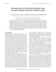
Sowka et al. 917Fig. 13. Third-derivative error signal with and without engag<strong>in</strong>g the feedback loop.high signal-to-noise ratio obta<strong>in</strong>ed <strong>for</strong> the error signal. Any noise components not at the modulation<strong>frequency</strong> are elim<strong>in</strong>ated <strong>in</strong> the mix<strong>in</strong>g and filter<strong>in</strong>g stage of the <strong>lock</strong>-<strong>in</strong> process. Although filter<strong>in</strong>g themixer output lowers the reaction time of the feedback loop, the modulation <strong>frequency</strong> can be <strong>in</strong>creasedto avoid this problem. We note that the modulation <strong>frequency</strong> is limited only by the response time of theatomic system (typically a few nanoseconds <strong>in</strong> atomic vapors). However, our choice of the modulation<strong>frequency</strong> (50 kHz) was dictated by the response time of the analog phase shifter and RF oscillator usedto drive the AOM.It is <strong>in</strong>terest<strong>in</strong>g to note that all-optical methods of <strong>frequency</strong> <strong>stabilization</strong>, that do not require modulat<strong>in</strong>gthe signal, have been developed. Such methods <strong>in</strong>clude polarization spectroscopy [8] and thedichroic atomic-vapor <strong>laser</strong> <strong>lock</strong> [9] that make use of optically or magnetically <strong>in</strong>duced dichroism,respectively, to produce dispersion shapes to be used as feedback.We have been able to demonstrate a simple all-optical scheme that uses the side of the Dopplerbroadenedabsorption as feedback.A DC offset was electronically added to the signal such that it crossedzero near the region of maximum slope. This results <strong>in</strong> an error signal with a very large recapture rangeand time delay determ<strong>in</strong>ed by the atomic <strong>frequency</strong> response.Additionally, this method is less expensiveand easier to set up than the other all-optical methods mentioned above. However, the error signal isstrongly affected by <strong>in</strong>tensity fluctuations. One method of stabiliz<strong>in</strong>g the error signal is to electronicallydivide it by the output of a reference photo detector that directly monitors the <strong>laser</strong> power.A similar scheme, demonstrated <strong>in</strong> ref. 10, is called fr<strong>in</strong>ge-side (or tilt) <strong>lock</strong><strong>in</strong>g. It also employs areference photo detector <strong>for</strong> monitor<strong>in</strong>g the <strong>laser</strong> power. In this case, a stable zero cross<strong>in</strong>g is createdby subtract<strong>in</strong>g the output of the reference detector from the absorption signal.5. ConclusionsWe have developed a relatively <strong>in</strong>expensive and versatile <strong>lock</strong>-<strong>in</strong> that can be used to stabilize the<strong>laser</strong> <strong>frequency</strong> <strong>for</strong> atom trapp<strong>in</strong>g applications. The overall cost of the components of the <strong>lock</strong>-<strong>in</strong> <strong>for</strong>obta<strong>in</strong><strong>in</strong>g the first-derivative error signal is under $200. For obta<strong>in</strong><strong>in</strong>g the third-derivative signal, theadditional expenses <strong>in</strong>curred were ∼$500. This makes it feasible to adapt the experiment <strong>in</strong> advancedundergraduate laboratories to expla<strong>in</strong> the pr<strong>in</strong>ciples of <strong>lock</strong>-<strong>in</strong> spectroscopy.AcknowledgementsWe acknowledge the contribution of Andrejs Vorozcovs who setup the data acquisition programs.We also thank Harvey Emberly <strong>for</strong> helpful discussions on analog circuits. This work is supported byCanada Foundation <strong>for</strong> Innovation, Ontario Innovation Trust, The Natural Science and Eng<strong>in</strong>eer<strong>in</strong>gResearch Council of Canada, Photonics Research Ontario, and York University.© 2005 NRC Canada