A home-built lock-in amplifier for laser frequency stabilization
A home-built lock-in amplifier for laser frequency stabilization
A home-built lock-in amplifier for laser frequency stabilization

Create successful ePaper yourself
Turn your PDF publications into a flip-book with our unique Google optimized e-Paper software.
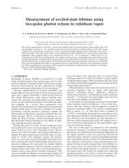
910 Can. J. Phys. Vol. 83, 2005Fig. 3. (a) standard setup <strong>for</strong> obta<strong>in</strong><strong>in</strong>g a Doppler-free saturated absorption signal: (1) weak probe beam,(2) counter-propagat<strong>in</strong>g <strong>in</strong>tense pump beam, (3) weak reference beam, (b) simplified setup <strong>for</strong> obta<strong>in</strong><strong>in</strong>g thesaturated absorption signal: The signal can be be observed by absorption or fluorescence detection.a)saturated absorption signalbeamsplitter1 2signal10 MHzω<strong>in</strong>com<strong>in</strong>gbeam3Rb vapor cellphotodiodessignalsignal1 GHzωsubtractorωDoppler-free saturated absorption signalb)<strong>in</strong>com<strong>in</strong>gbeamRb vapor cell1 2photodetectorsaturated absorption signals(absorption and fluorescence detection)photodetectorsignalsignalωωThis method <strong>in</strong>volves generat<strong>in</strong>g the counter-propagat<strong>in</strong>g beams by retro reflect<strong>in</strong>g the orig<strong>in</strong>al beamfrom the w<strong>in</strong>dow of the vapor cell and detect<strong>in</strong>g the signal through fluorescence or absorption. The firstderivative of this signal is unsuitable <strong>for</strong> <strong>lock</strong><strong>in</strong>g to a resonant <strong>frequency</strong> s<strong>in</strong>ce the Doppler backgroundcauses a shift <strong>in</strong> the position of the observed resonance peaks. However, the effect of the backgroundcan be nearly elim<strong>in</strong>ated if, <strong>in</strong>stead of the first derivative, the third derivative of the saturated absorptionsignal is used as feedback. The third derivative is obta<strong>in</strong>ed by mix<strong>in</strong>g the signal us<strong>in</strong>g the third harmonicof the modulation <strong>frequency</strong> [1].The rest of the paper is organized as follows. In Sect. 2, we model the shape of the first-derivativeerror signal. For the setup shown <strong>in</strong> Fig. 3b, we represent the shape of the saturated absorption signalas the sum of a Lorentzian (Doppler-free component) and a Gaussian (Doppler-broadened component).We show how the third derivative of the signal can be obta<strong>in</strong>ed by mix<strong>in</strong>g it with the third harmonicof the modulation <strong>frequency</strong> and expla<strong>in</strong> how this process greatly reduces the effect of the Dopplercomponent. Section 3 describes the experimental setup and gives details of simple analog circuits used<strong>in</strong> the <strong>lock</strong>-<strong>in</strong> <strong>amplifier</strong>. Section 4 shows the first- and third-derivative error signals obta<strong>in</strong>ed us<strong>in</strong>gthe <strong>home</strong> <strong>built</strong> <strong>lock</strong>-<strong>in</strong> and describes tests that show that the <strong>frequency</strong> stability is comparable to theper<strong>for</strong>mance of a commercial device.2. TheoryWe now expla<strong>in</strong> the basic features of the error signal. When the <strong>frequency</strong>-modulated <strong>laser</strong> is scannedover the desired Doppler-free resonance at ω 0 , the modulated absorption signal is recorded by a photodetector and sent to the <strong>lock</strong>-<strong>in</strong> <strong>amplifier</strong>. The <strong>lock</strong>-<strong>in</strong> multiplies this signal with the phase-shifted© 2005 NRC Canada