A home-built lock-in amplifier for laser frequency stabilization
A home-built lock-in amplifier for laser frequency stabilization
A home-built lock-in amplifier for laser frequency stabilization

You also want an ePaper? Increase the reach of your titles
YUMPU automatically turns print PDFs into web optimized ePapers that Google loves.
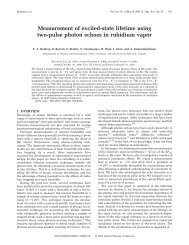
914 Can. J. Phys. Vol. 83, 2005Fig. 7. Diagram of phase-shift<strong>in</strong>g circuit.Fig. 8. Circuit diagrams: (a) voltage follower, (b) low-pass filter, and (c) ga<strong>in</strong> <strong>amplifier</strong>.a) <strong>in</strong>b)out c) <strong>in</strong>outout<strong>in</strong>Fig. 9. Experimental setup <strong>for</strong> obta<strong>in</strong><strong>in</strong>g the third harmonic of modulation signal.ΩΩ, 3Ωmixerhigh pass 3ΩΩfilter<strong>frequency</strong>doubler2Ω−2CR2 tan α1−tan 2 α ,the <strong>for</strong>mer complex quantity and is given by tan(φ) = . Us<strong>in</strong>g the identity tan(2α) =1−[CR] 2it can be shown that φ =−2 tan −1 CR. A variable resistor is used to control the phase difference.S<strong>in</strong>ce the maximum phase shift that can be achieved is π, we use two phase shifters <strong>in</strong> series to get thedesired range of 0 to 2π. A voltage follower (Fig. 8a) is <strong>in</strong>cluded be<strong>for</strong>e the phase shifters to serve as abuffer. S<strong>in</strong>ce this arrangement is easy to modify, it is possible to assemble additional phase shifters <strong>for</strong>display of the <strong>in</strong>-phase and quadrature components of the error signal.The absorption signal and the phase-shifted modulation are multiplied us<strong>in</strong>g a commercially availabledouble-balanced RF mixer. S<strong>in</strong>ce the DC component of the absorption signal lowers the output ofthe mixer, it is preferable to high-pass filter the absorption signal be<strong>for</strong>e send<strong>in</strong>g it to the mixer. Filter<strong>in</strong>gout the DC component is equivalent to elim<strong>in</strong>at<strong>in</strong>g the first term <strong>in</strong> the Taylor expansion (see (3) and(8)). This does not affect the error signal s<strong>in</strong>ce this term would be filtered out <strong>in</strong> any case, after mix<strong>in</strong>g.The output of the mixer is sent to a low-pass filter (Fig. 8b), with cutoff <strong>frequency</strong> less than , toelim<strong>in</strong>ate the AC components and produce the error signal. This signal is sent to a voltage <strong>amplifier</strong>circuit (Fig. 8c) to further control the amplitude of the error signal.To obta<strong>in</strong> the third-derivative error signal, the standard saturated absorption setup is replaced by oursimplified version seen <strong>in</strong> Fig. 3b.Also, we send the third-harmonic signal of the modulation <strong>frequency</strong> tothe <strong>lock</strong> <strong>in</strong>, <strong>in</strong>stead of the modulation itself. To generate the third harmonic of the modulation <strong>frequency</strong>,we use a commercial RF <strong>frequency</strong> doubler, another RF mixer, and a custom <strong>built</strong> high-pass filter witha steep cutoff below 150 kHz, as shown <strong>in</strong> Fig. 9. The third-derivative error signal is obta<strong>in</strong>ed byus<strong>in</strong>g a mixer and a low-pass filter as described previously. However, the amplitude A of the <strong>frequency</strong>modulation may have to be <strong>in</strong>creased to ensure that the third-derivative component of the absorptionsignal is significant over the modulation range.© 2005 NRC Canada