Cast Gate Valves Pressure Seal -Style A- Wedge Gate and ... - Pentair
Cast Gate Valves Pressure Seal -Style A- Wedge Gate and ... - Pentair
Cast Gate Valves Pressure Seal -Style A- Wedge Gate and ... - Pentair
- No tags were found...

Create successful ePaper yourself
Turn your PDF publications into a flip-book with our unique Google optimized e-Paper software.
Installation <strong>and</strong> Maintenance Instructions<strong>Pressure</strong> <strong>Seal</strong> <strong>Gate</strong> <strong>Valves</strong> -<strong>Style</strong> A-RAIMONDI<strong>Cast</strong> <strong>Gate</strong> <strong>Valves</strong> <strong>Pressure</strong> <strong>Seal</strong> -<strong>Style</strong> A-<strong>Wedge</strong> <strong>Gate</strong> <strong>and</strong> Parallel Slide ConfigurationContents1 Valve Storage 11.1 Preparation <strong>and</strong> Preservation for Shipment 11.2 H<strong>and</strong>ling Requirements 11.3 Storage <strong>and</strong> Preservation before Installation 22 Installation 22.1 Preparation before Installation 22.2 Installation Instructions 32.3 Valve Verification before Start Up 32.4 Operations Instructions 3Table I: Bolt Torque Figures for Packing Bolts 4Table II: Bolt Torque to Ensure Tightness of <strong>Pressure</strong> <strong>Seal</strong> Gasket 42.5 Periodic Valve Verification during Service 4Troubleshooting Guide 43 Maintenance 53.1 Packing Maintenance 53.2 Bonnet Gasket Replacement 54 Valve Removal 65 Greases <strong>and</strong> Special Tools 65.1 Greases 6Table III: Grease <strong>and</strong> Lubricant List 65.2 Special Tools 6Section 1 - Valve Storage1.1 Preparation <strong>and</strong> Preservation for ShipmentAll valves are properly packed in order to protect the parts that are subject to deterioration duringtransportation <strong>and</strong> storage on site. In particular, the following precautions should be taken:1. The valves must be packed with the wedge in the closed position.2. The weld ends surface shall be protected with suitable protective like Deoxaluminite. The endshall be closed with plywood or plastic disc fixed at the edge by strips.3. All actuated valves must be carefully securely palleted or crated, in order to ensure that theparts of actuator (especially pneumatic piping or accessories) do not extend beyond the skid/crate.4. The type of packing must be defined in the Customer’s Order <strong>and</strong> shall be appropriate to ensuresafe transportation to final destination <strong>and</strong> eventual conservation before installation.1.2 H<strong>and</strong>ling RequirementsA - Packed <strong>Valves</strong>Crates: Lifting <strong>and</strong> h<strong>and</strong>ling of the packed valves in crates will be carried out by a fork lift truck, bymeans of the appropriate fork hitches.Cases: The lifting of packed valves in cases should be carried out in the lifting points <strong>and</strong> atthe center of gravity position which have been marked. The transportation of all packedmaterial must be carried out safely <strong>and</strong> following the local safety regulations.B - Unpacked <strong>Valves</strong>1. The lifting <strong>and</strong> the h<strong>and</strong>ling of these valves has to be carried out by using appropriate means<strong>and</strong> at respecting the carrying limits. The h<strong>and</strong>ling must be carried out on pallets, protecting themachined surfaces to avoid any damage.2. With valves of large dimensions, the sling <strong>and</strong> the hooking of the load must be carried out usingthe appropriate tools (brackets, hook, fasteners, ropes) <strong>and</strong> load balancing tools in order toprevent them from falling or moving during the lifting <strong>and</strong> h<strong>and</strong>ling.www.pentair.com/valves<strong>Pentair</strong> reserves the right to change the contents without noticeRAILT-0028-EN-1307
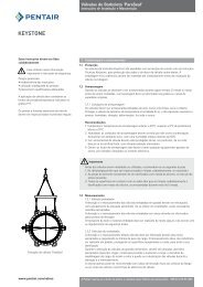
Installation <strong>and</strong> Maintenance Instructions<strong>Pressure</strong> <strong>Seal</strong> <strong>Gate</strong> <strong>Valves</strong> -<strong>Style</strong> A-2.2 Installation Instructions<strong>Gate</strong> valves are normally installed in horizontal pipe with vertical stem.These valves can also be installed in vertical or horizontal pipe with stem other than vertical, butthis may require special construction depending on valve size, service condition, material <strong>and</strong> typeof operator.For a correct operation, Raimondi recommends that the valve shall be installed <strong>and</strong> orientedfollowing the indications of fig. 2.This can help minimize any problem associated with solid particles present in the fluid thatotherwise could deposit in the lower part of the body <strong>and</strong> be obstacle to the wedge completeclosure.Unless otherwise recommended by Raimondi, the valve should be installed with the wedge inthe closed position, to ensure that the seat ring in the wedge is not damaged during installation.Particular care should be taken with those valves equipped with ‘fail-open’ actuators.For operating temperatures above 200°C (392°F) thermal insulation of the valve body isrecommended.H<strong>and</strong>ling <strong>and</strong> lifting of the valves during installation MUST be performed following the same criteria<strong>and</strong> instructions described in previous points “1.2 H<strong>and</strong>ling Requirements” <strong>and</strong> “1.3 Storage <strong>and</strong>Preservation before Installation”.Buttweld <strong>Valves</strong>Position the valve <strong>and</strong> check the alignment with the pipe, then proceed with welding, inaccordance with the applicable welding procedure.Figure no. 2Installation positionsrecommended90° max.ImportantAfter the valves installation <strong>and</strong> before the line testing, it is recommended to perform anaccurate cleaning of the lines to eliminate dirt <strong>and</strong> any foreign objects that could seriouslyjeopardize the tightness between seat/disc <strong>and</strong> the correct operation of the valve.2.3 Valve Verification before Start Up1. Tighten the packing just enough to prevent stem leakage. Over-tightening will decrease packinglife <strong>and</strong> increase operating torque. The bolt torque figures for the packing bolts can be calculatedas indicated in Table I.2. Check the operation of the valve by stroking it to “full open” <strong>and</strong> “full close”.3. If the valve has been stored for a long time, check the bolt torque for bolting (pos. 31) inaccordance with table II.ImportantIf piping system is pressurized with water for testing, <strong>and</strong> in case the piping system has beenshut down after testing for a long time, the following recommendations should be adopted.a. Use corrosion inhibitor with water to pressurize the piping systemb. After testing, the piping system should be depressurized <strong>and</strong> the test water completelydrained.2.4 Operations Instructions1. <strong>Style</strong> A Series <strong>Gate</strong> <strong>Valves</strong> do not require special care to work properly.The following instructions will help provide a satisfactory <strong>and</strong> long life service.2. Make sure to perform periodic valve verification as described in paragraph 2.5.3. In case of actuated valves always follow the specific instructions given by the actuator’smanufacturer.4. Never change the setting of torque <strong>and</strong>/or limit switches which have been carefully set duringthe final test at Raimondi workshop.<strong>Pentair</strong> reserves the right to change the contents without notice page 3
Installation <strong>and</strong> Maintenance Instructions<strong>Pressure</strong> <strong>Seal</strong> <strong>Gate</strong> <strong>Valves</strong> -<strong>Style</strong> A-Table I: Bolt Torque Figures for Packing BoltsFor System pressures < 2533 psiTorque (ft lbs) = (24.87) x (OD2 _ ID2) x (d)Torque (Nm) = multiply Torque (ft lbs) x 1.3558Where:For System pressures ≥ 2533 psiTorque (ft lbs) = (S.P./101.8) x (OD2 _ ID2) x (d)OD = Stuffing Box Bore (ln.)ID = Stem Diam (In.)d = Gl<strong>and</strong> Stud Diam (in.)S.P. = System <strong>Pressure</strong> (psi)This “Torque method” may result in more or less than 30% compression.2.5 Periodic Valve Verification during ServiceA - Normal Check1. Verify monthly that there is no leakage from packing or in the body/bonnet area. If the leakagehas been detected from the packing, tighten nuts according to the procedure described inSection 3.If the leakage does not stop, follow the procedure for packing maintenance (3.1).If the leakage has been detected from the body/bonnet, tighten the nuts (pos. 31) as indicated inTable II.If the leakage does not stop, follow the maintenance procedure for the replacement of the body/bonnet gasket (3.2, 3.3).2. Every 2 / 3 months, depending on operating frequency, verify the greasing of bearings <strong>and</strong> stemthread.3. For actuated valves, in addition to the above, please refer also to the warnings in the actuatormanual.Table II:Bolt Torque to Ensure Tightness of<strong>Pressure</strong> <strong>Seal</strong> GasketPosition 31 for <strong>Gate</strong> <strong>Valves</strong>Stud Torque ft.lbs. Torque Nm3/8 18 24,51/2 37 505/8 74 1003/4 125 1707/8 207 2801 310 4201 1/8 443 6001 1/4 627 8501 3/8 811 1100ImportantTo ensure tightness of <strong>Pressure</strong> <strong>Seal</strong> gasket,pull up bolts must be tightened when valve isunder fully hydrostatic test pressure.B - Preventive Actions1. Every 3 months verify the tightness of gl<strong>and</strong> bolts.2. Every 6 months on motorized valves <strong>and</strong> every 8 months on h<strong>and</strong> operated valves, grease stem<strong>and</strong> bearings.3. Every 12 months check the travel of the gl<strong>and</strong> follower, setting a new packing when the end ofthe travel is approaching.4. Every 4 years disassemble the critical service valves <strong>and</strong>/or actuated valves, verifying the sealingsurfaces <strong>and</strong> lap them again when necessary. Substitute the bonnet gasket <strong>and</strong> the packing,grease the stem.5. For the actuator, proceed as indicated in its maintenance manual.Troubleshooting GuideSymptomStem packing leakingPossible Cause1. Gl<strong>and</strong> flange nuts too loose2. Packing damagedSolution1. Tighten gl<strong>and</strong> flange nuts.2. Replace packing(See Paragraph 3.1)Body-Bonnet leaking1. Gasket bolting loose(pos 31)2. Gasket damage1. Tighten bolting (pos 31)2. Replace the gasketValve leaking1. Valve not fully closed2. Debris trapped in valve3. <strong>Seal</strong>ing surface damaged1. Close valve2. Cycle <strong>and</strong> flush (with valve open)to remove debris3. Recondition the seat surfaceJerky operation1. Packing is too tight2. Air supply inadequate (forpneumatic act.)1. Loosen gl<strong>and</strong> nuts, cycle thevalve, retighten2. Increase air supply pressureBack seat leaking1. Back seat damage1. Replace the back seat<strong>Pentair</strong> reserves the right to change the contents without notice page 4
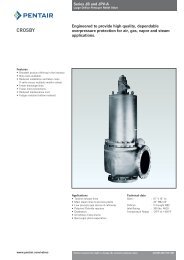
Installation <strong>and</strong> Maintenance Instructions<strong>Pressure</strong> <strong>Seal</strong> <strong>Gate</strong> <strong>Valves</strong> -<strong>Style</strong> A-Section 3 - MaintenanceThe <strong>Style</strong> A Series <strong>Valves</strong> have been designed to require minimum maintenance.This manual describes on site repairs as:- Packing Replacement- Body/Bonnet Gasket ReplacementAll the other repairs should be performed by Raimondi or Nominated Service Company.3.1. Packing MaintenanceIf leakage is observed through the packing, tighten the gl<strong>and</strong> nuts slowly <strong>and</strong> evenly until theleakage stops.CautionDo not over-tighten packing gl<strong>and</strong> nuts. Over-tightening will increase the torque required tooperate the valve.When tightening the gl<strong>and</strong> nut, use half-turn increments until leakage has stopped.Please refer to Figure no. 4.To replace the packing proceed as follows:WarningBefore starting any maintenance, depressurize, drain <strong>and</strong> vent the line; check that the valvesare not in temperature; disconnect any electrical power supply.Failure to do so may cause serious personal injury <strong>and</strong>/or equipment damage.1 = Braided graphite2 = Die formet graphite (5 or 6 ring)3 = Metal ringFigure no. 31. Open completely the valve up to the backseat position.2. Remove the nuts (16) of the gl<strong>and</strong> bolts (15)3. Lift the gl<strong>and</strong> flange (10) <strong>and</strong> the gl<strong>and</strong> (9)4. Remove the worm-out packing using a hooking wire5. For a better tightness, proceed to an accurate cleaning of the stem <strong>and</strong> stuffing box <strong>and</strong> makesure there are no scratches or signs of seizing6. The repacking shall be carried out by placing one ring at a time around the stem, inside thestuffing box <strong>and</strong> by making sure that they are correctly oriented. Press it into the bottom (referto Figure no. 3).7. When the stuffing box is filled, replace the gl<strong>and</strong> (9) <strong>and</strong> gl<strong>and</strong> flange (10) in their originalposition.8. Tighten gl<strong>and</strong> nuts in accordance with Table I (Bolt Torque figures for Packing Bolts).9. Cycle the valve.10. Pressurize the line.11. If a leakage is detected, tighten the gl<strong>and</strong> nuts slowly <strong>and</strong> evenly until the leakage stops.Figure no. 43.2 Bonnet Gasket ReplacementWarningBefore starting any maintenance, depressurize, drain <strong>and</strong> vent the line; check that the valvesare not in temperature; disconnect any electrical power supply.Failure to do so may cause serious personal injury <strong>and</strong>/or equipment damage.<strong>Pentair</strong> reserves the right to change the contents without notice page 5
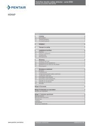
Installation <strong>and</strong> Maintenance Instructions<strong>Pressure</strong> <strong>Seal</strong> <strong>Gate</strong> <strong>Valves</strong> -<strong>Style</strong> A-Fig. no. 5Lifting lugsfor DN = 6”For DN = 4” For DN = 3”Please refer to Figure no. 5.1. Unscrew the body bonnet nuts (pos.12) <strong>and</strong> the gl<strong>and</strong> nuts (pos.16)2. Lift up the yoke (pos.24) operating by the h<strong>and</strong>wheel or gearbox h<strong>and</strong>wheel3. When the stem nut is free from the stem threads, lift up the yoke.4. Unscrew the nuts (pos.31).5. Remove the retaining ring (pos.311).6. Remove the segment rings, push them out from the body groove by using the body holesplaced radially on the top of the body.7. Lift up the bonnet (pos.6) <strong>and</strong> pressure seal body gasket (pos.5). Make sure not to damage thepacking. We suggest to replace the packing when changing the body gasket.8. Carefully clean all the gasket housing <strong>and</strong> lubricate with suitable grease.9. Replace the body gasket.10. Reassemble all parts following backwards the above mentioned steps.CautionThe nuts (pos.31) need to be retightenedafter valve first pressurization, as indicatedin Table II.Section 4 - Valve RemovalIf the valve needs to be removed from the line for some extraordinary reason, the user shouldensure the following:1. The valve is depressurized, drained <strong>and</strong> vent.2. The pipe shall be cut as far away from the valve as possible.Section 5 - Greases <strong>and</strong> Special Tools5.1 GreasesTo lubricate the bearings on manual <strong>and</strong> gearbox operated valves, we suggest to use the greaseAGIP GRMUEP2 or an equivalent product, as showed in the following table:Table III: Grease <strong>and</strong> Lubricant ListManufacturer GreaseAGIPGRMUEP2APIPGX2BPGREASE LTX2ESSO BEACON 2FINAFINAGREASE HP FINAGREASE EPL2MOBILMOBILUX EP2Q8REMBRANDT EP2SHELLALVANIA R2 SUPERGREASE ATEXACOMULTIFAK EP2 GREASE L2TOTAL MULTIS EP2 MULTIS 2VISCOL SIGNAL ROLSFER 2STATOILUHIWAYLI LI G2For the lubrication of the stem thread, use the grease SIGNAL CEP 30 produced by Viscol. As analternative you can utilize:- CEPLATTYN 300 produced by REINER-FUCHS- GRAFLOSCON produced by KLUBERYou can also use a grease having more than 25% pure graphite content (carbon 98%) granulometry5m, without any abrasive agent.For the lubrication of the actuator, refer to the relevant manual.5.2 Special ToolsNo special tool required for the Maintenance Operation described in this Manual.<strong>Pentair</strong> reserves the right to change the contents without notice page 6