DS9638 RS-422 Dual High Speed Differential Line Driver
DS9638 RS-422 Dual High Speed Differential Line Driver
DS9638 RS-422 Dual High Speed Differential Line Driver

You also want an ePaper? Increase the reach of your titles
YUMPU automatically turns print PDFs into web optimized ePapers that Google loves.
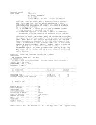
Absolute Maximum Ratings (Note 1)If MilitaryAerospace specified devices are requiredplease contact the National Semiconductor SalesOfficeDistributors for availability and specificationsStorage Temperature RangeCeramic DIPMolded DIP and SO-8Lead TemperatureCeramic DIP (Soldering 60 sec)Molded DIP (Soldering 10 sec)b65Ctoa175Cb65Ctoa150C300C265CRecommended Operating ConditionsMaximum Power Dissipation at 25CCavity Package1300 mWMolded Package930 mWSO Package810 mWV CC Lead Potential to Groundb5V to 7VInput Voltageb05V to a7VDerate cavity package 87 mWC above 25C derate molded DIP package75 mWC above 25C derate SO package 65 mWC above 25C<strong>DS9638</strong>M<strong>DS9638</strong>CMin Typ Max Min Typ Max UnitsSupply Voltage (V CC ) 45 50 55 475 50 525 VOutput Current HIGH (I OH ) b50 b50 mAOutput Current LOW (I OL ) 50 40 50 mAOperating Temperature (T A ) b55 25 125 0 25 70 CElectrical Characteristics Over recommended operating temperature and supply voltage ranges unless otherwisespecified (Notes23)Symbol Parameter Conditions Min Typ Max UnitsV IH Input Voltage HIGH 20 VV IL Input Voltage LOW 0Ctoa70C 08b55Ctoa125CV IC Input Clamp Voltage V CC e Min I I eb18 mA b10 b12 VV OH Output Voltage HIGH V CC e Min I OH eb10 mA 25 35V IH e V IH Min V IL e V IL MaxI OH eb40 mA 20V OL Output Voltage LOW V CC e Min V IH e V IH Min V IL e V IL Max I OL e 40 mAI I Input Current at Maximum V CC e Max V I Max e 55VInput Voltage0505VVV50 mAI IH Input Current HIGH V CC e Max V IH e 27V 25 mAI IL Input Current LOW V CC e Max V IL e 05V b200 mAI OS Output Short Circuit Current V CC e Max V O e 0V (Note 4) b50 b150 mAV T V T Terminated Output Voltage See Figure 1 20 VV T –V T Output Balance 04 VV OS V OS Output Offset Voltage 30 VV OS –V OS Output Offset Balance 04 VI X Output Leakage Current T A e 25Cb025V k V Xk 55V100 mAI CC Supply Current V CC e 55V(Both <strong>Driver</strong>s) All input at 0V 45 65 mANo LoadNote 1 ‘‘Absolute Maximum Ratings’’ are those values beyond which the safety of the device cannot be guaranteed They are not meant to imply that the devicesshould be operated at these limits The tables of ‘‘Electrical Characteristics provide conditions for actual device operationNote 2 Unless otherwise specified minmax limits apply across the b55C toa125C temperature range for the <strong>DS9638</strong>M and across the 0C toa70C range forthe <strong>DS9638</strong>C All typicals are given for V CC e 5V and T A e 25CNote 3 All currents into the device pins are positive all currents out of the device pins are negative All voltages are referenced to ground unless otherwisespecifiedNote 4 Only one output at a time should be shortedhttpwwwnationalcom 2