You also want an ePaper? Increase the reach of your titles
YUMPU automatically turns print PDFs into web optimized ePapers that Google loves.
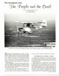
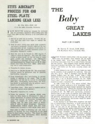
Fokker Triplane Planning<br />
In this view of the miniature construction model, the<br />
original Fokker Triplane structural configuration is evident.<br />
Simplicity is the keynote in this structure.<br />
IN PLANNING the necessary modifications to adapt<br />
the original Fokker Triplane structure to take a modern<br />
reliable engine and make other desirable changes,<br />
I have found it wise to build models to help work out<br />
proposed designs. <strong>The</strong> accompanying photos show a pair<br />
of miniature fuselage frames made for this purpose. One<br />
shows the essentially original Fokker structure while<br />
the other shows its extensively modified counterpart.<br />
In making these models soldered metal construction<br />
proved better and somewhat faster than the conventional<br />
cemented wooden method commonly used for flying<br />
models. When using a scale of IVfe in. equals 1 ft. 0 in.,<br />
which is very convenient for scaling purposes, it will be<br />
found that regular copper-coated mild steel welding rods<br />
of l /s in., 3/32 in. and 1/16 in. diameter correspond to<br />
1 in., % in., and Vz in. tubing sizes. It was found that<br />
steel rods are better suited to this project than comparable<br />
bronze brazing rods, because the steel conducts the<br />
heat of soldering much less rapidly, thus allowing additional<br />
members to be added to a cluster without the<br />
whole joint springing apart. Since the real purpose of the<br />
model is to better visualize different trussing schemes<br />
it becomes an advantage to be able to remove or add<br />
members at will.<br />
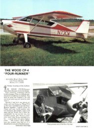
"FLY BABY" . . .<br />
(Continued from page 14)<br />
I haven't done any aerobatics in it, mainly because<br />
I'm no good at them. Only Dave Gauthier has. <strong>The</strong>y looked<br />
good from the ground, and he seemed pleased after the<br />
short time he'd tried it. I'll let a real "pro" have a try<br />
at it and give a report later. As for spins, it's a hard<br />
fight to get it into one, and then it comes out by itself.<br />
Stall is clean, with no tendency to drop either wing. With<br />
the wires, it's easy to rig the wings to a bit of wash-out<br />
so that there is plenty of aileron control through the<br />
stall. Load factor? Jim Wickham ran a stress analysis<br />
as the subject of a Chapter 26 EAA meeting, and it came<br />
up as 7.<br />
So there it is. I'll admit that it's not an airplane to<br />
By John Doyle, EAA 2931<br />
P. O. Box 13, Andover, Mass.<br />
Generally, rods should be snipped to approximate<br />
length with heavy diagonal cutters and then filed to<br />
exact dimensions. It's unnecessary to make rounded<br />
notches at the ends of struts as the solder fills the joint<br />
well, but scarves often have to be filed to shape where<br />
clusters occur. Splices, such as shown in the photos immediately<br />
behind the cockpit where the longeron tubes<br />
telescope into each other, are best accomplished by scarfing<br />
both members and soldering them together before<br />
jig assembly. As in the building of the full-size article<br />
a suitable jig is absolutely necessary to align the members<br />
in proper position while soldering is done. <strong>The</strong><br />
Fokker Triplane example lent itself well to the standard<br />
side-frame type of construction. With a simple line<br />
drawing of the frame tacked to a soft pine board 1 in.<br />
by No. 18 brads were driven along both sides of the<br />
members to hold them in place. Other jigs were found<br />
useful to hold the completed side-frames in relative position<br />
while cross pieces were added.<br />
John Doyle's redesigned Fokker Triplane fuselage points<br />
out the heavy reinforcing of the entire structure, especially<br />
in the forward bays to acccommodate a modern,<br />
reliable engine.<br />
A Weller WD-135 soldering gun gave good results,<br />
using 50/50 wire solder and Nokorode Fluid Flux. Acid<br />
type fluxes should be avoided because rusting will occur,<br />
making resoldering operations difficult. Rosin type<br />
fluxes are also apt to prove unsatisfactory for they generally<br />
do not work well on steel.<br />
please everybody, especially those who have had previous<br />
experience with homebuilts and have built up their<br />
own ideas as to just what they want. I think that those<br />
to whom speed and zip aren't so important will find it<br />
"<strong>The</strong> Mostest" airplane that they can produce for the least<br />
investment of money and labor. Careful notes were kept<br />
on both of these. <strong>The</strong> raw materials in the original ship<br />
cost $375, and the "used hardware" consisting of a majored<br />
engine, used metal prop, instruments, wheels,<br />
brakes, fuel tank, etc., came to $675 for a total of $1,050.<br />
<strong>The</strong>se at average market prices in 1960. Good horsetraders<br />
and scroungers can doubtless cut this down considerably.<br />
Time to build "<strong>Fly</strong> <strong>Baby</strong>" the first time, averaging<br />
out the labor skills involved, was 720 hours, which<br />
works out to about two hours a day for a year. £<br />
SPORT AVIATION 15