Create successful ePaper yourself
Turn your PDF publications into a flip-book with our unique Google optimized e-Paper software.
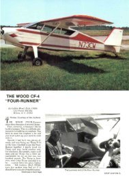
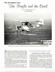
(Photo by Bowers)<br />
All the tooling needed to assemble the fuselage sides—<br />
a flat work area and some notched two-by-fours. <strong>The</strong>re<br />
are only two scarfed plywood splices in the whole airplane<br />
—visible halfway toward the tail.<br />
the average chord, or span squared divided by wing area)<br />
increases, induced drag, especially at the low speed range,<br />
is decreased. Racers, which don't care about easy landing,<br />
have ratios as low as 3 for good high-speed flight<br />
but the safe-and-slow jobs want higher ratios, at least<br />
over 6. For sailplanes, the A.R. alone is a pretty good<br />
index of performance, with a high for the super-dupers<br />
of 24 to get 40-to-l glide and 16-18 the best structural<br />
compromise. <strong>The</strong>re just aren't any in production any more<br />
with aspect ratios under 10. In modern airplanes, the<br />
Piper PA-15/17 "Vagabond" with A.R. 5.8 and a span of<br />
27 ft. just couldn't compare with the old J-3 "Cub" which<br />
had 35 ft. and an A.R. of 7, and the four-place "Vagabond"<br />
developments, the "Clipper" and the "Pacer" never<br />
really arrived until the horsepower was upped from the<br />
original 115 to an eventual 160.<br />
As a result of all this, the new design ended up with<br />
a span of 28 ft., an A.R. of 6.5, 120 sq. ft. of wing area,<br />
and a good long tail moment arm. Another distinctive<br />
fe; ture of the <strong>Story</strong> was the simple wire bracing of the<br />
two-spar wings to the upper longerons and to a rigid<br />
larding gear. Where the <strong>Story</strong>, in common with the Ryan<br />
ST of 1934 and the Boeing P-26 of 1932, ran the lower<br />
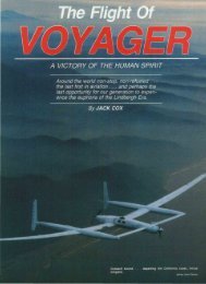
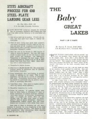
View into the cockpit<br />
showing the finished<br />
forward spar<br />
bulkhead and the<br />
hydraulic brake<br />
master cylinder<br />
mounting. Note the<br />
inboard plywood<br />
covering over the<br />
double bottom longerons<br />
and the forward<br />
bay. <strong>The</strong> diagonals<br />
carry landing<br />
gear loads in the<br />
forward bays but<br />
only serve to stiffen<br />
the plywood skin in<br />
the bays behind the<br />
cockpit. Dural angles<br />
in forward corners<br />
transmit engine<br />
mount loads into<br />
the fuselage sides.<br />
Floorboards rest on<br />
top of the double<br />
longeron structure.<br />
(Photo by Bowers)<br />
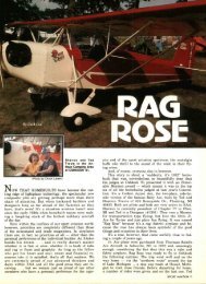
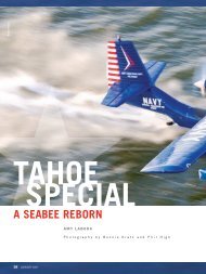
(Photo by Bowers)<br />
Two fuselage sides—one with the plywood skin and one<br />
with the temporary gussets. Note the "double" bottom<br />
longerons. Forward upright is birch or oak; other truss<br />
members are spruce.<br />
(Photo by Bowers)<br />
Interior of the fuselage looking toward the nose from<br />
behind the cockpit, showing the corner bows that stiffen<br />
the two wing carry-through bulkheads. Diagonal in front<br />
is strictly temporary.<br />
wires to auxiliary structure behind the wheels, the new<br />
design followed the even earlier style of the Howard<br />
"Pete", Heath "<strong>Baby</strong> Bullet", and the earlier Curtiss<br />
Military Racers by cleaning up the whole under carriage,<br />
using a straight-across axle, and attaching the wires right<br />
to the axle ends. Consideration was given to using struts<br />
above the wings instead of wires, as on the Stits "Playboy",<br />
but the longer span meant that the strut-wing intersection<br />
angle would be very acute and produce a big<br />
interference problem, causing high drag and a significant<br />
loss of lift. It's good to be able to learn by the experience<br />
of others, and since Fred Sindlinger of Seattle<br />
had considerable trouble with his short-span original design<br />
in this area, it was decided to eliminate the problem<br />
by using wires. This decision was backed up by<br />
some of the design articles appearing in SPORT AVIA-<br />
TION and the EAA manuals at the time and the fact that<br />
Vs in. 1 x 19 stranded stainless steel wire, which tests<br />
2,100 Ibs., is a lot cheaper than streamlined steel tubing.<br />
A couple of features that it shared with the 1940 gas<br />
model were the laminated wood wing tip bow construction<br />
and tip shape, and the vertical tail shape with small<br />
underfin. <strong>The</strong>se had practically become a Bowers trademark,<br />
having been used on all my gas models from 1937<br />
to 1949, when I built my last one.<br />
With the new design pretty well firmed up and the<br />
EAA contest now under way, we decided that Ron would<br />
build the new one and enter it as "<strong>Fly</strong> <strong>Baby</strong> II" while I<br />
built the original 1951 design as "<strong>Fly</strong> <strong>Baby</strong> I". Ron got<br />
started first, and had both fuselage side frames built,<br />
covered with plywood, and joined together when he got<br />
a remote-base assignment and had to give it up. Since<br />
(Continued on next pog«)<br />
SPORT AVIATION 5