DMX and DMH
DMX and DMH
DMX and DMH

You also want an ePaper? Increase the reach of your titles
YUMPU automatically turns print PDFs into web optimized ePapers that Google loves.
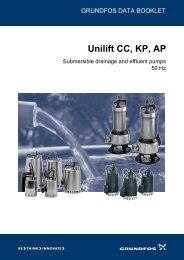
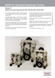
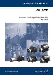
Features <strong>and</strong> benefits<strong>DMX</strong> <strong>and</strong> <strong>DMH</strong><strong>DMX</strong>Reliable diaphragm dosingfrom 4 to 2* x 765 l/h.Fig. 1 <strong>DMX</strong>Versatility through choiceThe Grundfos <strong>DMX</strong> is a series of high-quality diaphragmpumps suitable for many uses, e.g. drinkingwater treatment, wastewater treatment (settlement/sludge treatment), <strong>and</strong> the pulp/paper <strong>and</strong> textile industries.The range is designed to be highly versatile, a factwhich is reflected in the wide flow range covered <strong>and</strong>the choice of dosing head sizes, materials <strong>and</strong> accessoriesavailable. If in doubt, ask us – we will help youconfigure the <strong>DMX</strong> that is best for you.Tried. Tested. Truly reliableThe Grundfos <strong>DMX</strong> series has proven its worth in dosingapplications worldwide, demonstrating how itssturdy diaphragm-based design <strong>and</strong> high-qualitymotors combine versatile dosing with minimum maintenancerequirements. Now updated as an integratedpart of the Grundfos dosing range, the Grundfos <strong>DMX</strong>series is as trustworthy as ever.Accurate dosing. All the timeThe diaphragm design ensures that the dosing flownever varies by more than ±1.5 per cent. And the linearityis kept below 4 per cent at all times.Smoothness comes st<strong>and</strong>ardThe Grundfos <strong>DMX</strong> series employs sophisticated drivetechnology <strong>and</strong> gear kinematics to ensure smooth, lowpulsationdosing.TM03 2134 3705Motors to match application needsIf your application involves specific motor requirements,the versatile <strong>DMX</strong> range can match that, too:Grundfos <strong>DMX</strong> dosing pumps can be configured withservomotors or Atex-class motors as required. As ever,your Grundfos consultant is happy to help you choosethe right <strong>DMX</strong> for you.Choose the materials – <strong>and</strong> size – that suit youThe smaller models in the Grundfos <strong>DMX</strong> series areenclosed in plastic which is resistant to chemicals <strong>and</strong>offers all the protection necessary for most applications.The larger models have a robust cast-aluminiumgearbox with an epoxy coating to meet all applicationneeds. You also get a choice of materials for parts thatcome into contact with the chemicals you wish to dose,so it is easy to get a Grundfos <strong>DMX</strong> with exactly thedegree of chemical resistance you want.Large models remain compactThe <strong>DMX</strong> range comprises ten different dosing headsizes, but careful design work has kept them compact,making it easy for you to connect several pumps rightnext to each other if necessary.Twin-head versions saves you moneyThe two dosing heads fitted in the twin-head versions ofthe <strong>DMX</strong> range offers you a very cost-efficient way ofdosing two different chemicals to suit your application.Of course, the extra capacity offered by twin-head versionscan also be used to gain higher flow rates for asingle chemical.Accessories ensure perfect system integrationA wide range of accessories specially designed for theGrundfos <strong>DMX</strong> series help optimise performance. Thismakes commissioning fast <strong>and</strong> easy. Other accessoriesare also available to make sure that your Grundfos<strong>DMX</strong> fits your system exactly – e.g. pressure loadingvalves for dosing systems with no or varying back pressure.* Only <strong>DMX</strong> model 226 is available with two dosingheads.3
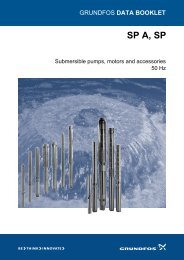
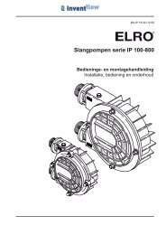
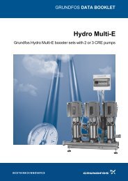
Features <strong>and</strong> benefits<strong>DMX</strong> <strong>and</strong> <strong>DMH</strong><strong>DMH</strong>Strong piston/diaphragm dosingfrom 2.2 to 2* x 1150 l/h.Enjoy the Teflon ® effectThe <strong>DMH</strong> pumps can shrug off almost anything. Theyare fitted with Teflon ® (PTFE) diaphragms, <strong>and</strong> theparts that come into contact with the liquids dosed areavailable in material combinations to suit virtually alldosing scenarios.Ready for tough applicationsThe tough application areas within the oil refineryindustry can also benefit from the Grundfos <strong>DMH</strong>range: several models have been designed <strong>and</strong>approved in accordance with API 675.*All <strong>DMH</strong> pumps are available with two dosing heads.TM03 2133 3705Fig. 2 <strong>DMH</strong>The preferred choice for complex tasksThe Grundfos <strong>DMH</strong> range is a series of extremelystrong, robust pumps for situations where you need asubstantial dosing range <strong>and</strong> high-pressure capability.The pumps are accurate to within ±1 per cent of therated flow, making the <strong>DMH</strong> series the preferred choicefor complex tasks <strong>and</strong> automatic process integration.And their strength is a matter of public record: Customersworldwide have enjoyed years of trouble-free operationfrom their <strong>DMH</strong> pumps.Get the pump configuration you needA number of different product configurations are availableto match your requirements. For example, you canchoose between electric or pneumatic servomotors, optfor an AC inverter-controlled motor, pick special dosingheads with electrical heating, or have your pumps fittedwith double diaphragms with failure indication. If indoubt, ask your Grundfos consultant to help you choosethe best configuration for the task.Prepared for extreme situationsAMS diaphragm protection keeps both the pump <strong>and</strong>overall application protected against extensive highpressures in the event of blockages in the dischargeline. Similarly, pressure-relief valves guard the pumpagainst excessive pressure in the system.Stroke-length adjustment ensures precise dosingVery precise <strong>and</strong> accurate stroke-length adjustment,with setting carried out using a Vernier scale, bringsyou optimum dosing with a repeatability of only ±1%.4
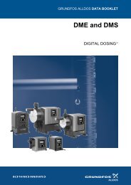
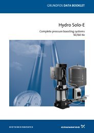
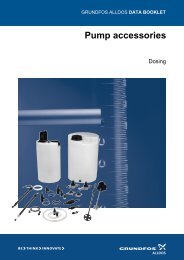
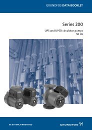
Performance range<strong>DMX</strong> <strong>and</strong> <strong>DMH</strong><strong>DMX</strong>, 4 to 765 l/hp[bar]16<strong>DMX</strong>50 Hz1412108642005 13.7 50 100 190 280 460 765Q [l/h]TM03 2914 5005Fig. 3 Performance range, <strong>DMX</strong>, 4 to 765 l/h<strong>DMH</strong>, 2.2 to 1150 l/hp[bar]200<strong>DMH</strong>50 Hz1005016100050 105 222 276 500 1150Q [l/h]TM03 2915 5005Fig. 4 Performance range, <strong>DMH</strong>, 2.2 to 1150 l/h5
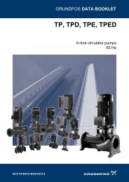
Identification<strong>DMX</strong> <strong>and</strong> <strong>DMH</strong>Type keyExample: <strong>DMX</strong> 160 - 5 B PP /E /T -X -E 1 QQ X E0Type rangeMotor variant<strong>DMX</strong> E0 PTC motor for frequency control<strong>DMH</strong>Motor type EEx de C T3, 3 x 400 V,E150 Hz (only <strong>DMX</strong>-B or <strong>DMX</strong>-AT)Maximum flow [l/h]Motor type EEx de C T4, 3 x 400 V,E250 Hz (only <strong>DMX</strong>-B or <strong>DMX</strong>-AT)Maximum pressure [bar]* Only pumps of 0.37 kW <strong>and</strong> below.E3Mains plugAPI approvalControl variantX No plugB St<strong>and</strong>ard F EU (Schuko)AR* Etron E26 (analog/pulse control) B USA, CanadaAT3AT4AT5AT6AT7Servomotor, 1 x 230 V, 50/60 Hz supply,4-20 mA controlServomotor, 24 V, 50/60 Hz supply,4-20 mA controlServomotor, 1 x 115 V, 50/60 Hz supply,4-20 mA controlServomotor, 1 x 230 V, 50/60 Hz supply,4-20 mA control, EEx d II BT 4Servomotor, 1 x 115 V, 50/60 Hz supply,4-20 mA control, EEx d II BT 4IEAustralia, New Zeal<strong>and</strong>, TaiwanSwitzerl<strong>and</strong>Connection, suction/dischargeB6 Pipe 4/6 mm4 Tube 6/9 mm6 Tube 9/12 mmB9 Tube 19/27 mm, PVCQ Tube 19/27 mm <strong>and</strong> 25/34 mmS Tube 0.375"/0.5”A Threaded Rp ¼"Dosing head variantA1 Threaded Rp ¾"PP Polypropylene A2 Threaded Rp 1 ¼"PV PVDF (polyvinylidene fluoride) V Threaded NPT ¼"PVC Polyvinyl chloride A9 Threaded NPT ½", maleSS Stainless steel, DIN 1.4401 A3 Threaded NPT ¾"Y Hastelloy C A7 Threaded NPT ¾", malePV-R PVDF + integrated relief valve A4 Threaded NPT 1 ¼"PVC-R PVC + integrated relief valve A8 Threaded NPT 1 ¼", malePP-L PP + integrated diaphragm leakage detection K Cementing d. 40 mmPV-L PVDF + integrated diaphragm leakage detectionCementing d. 40 mmB8PVC-L PVC + integrated diaphragm leakage detection<strong>and</strong> flange DN 32SS-L SS + integrated diaphragm leakage detection B1 Tube 6/12 mm/cementing d. 12 mmY-L Y + integrated diaphragm leakage detectionPV-RLB2 Tube 13/20 mm/cementing d. 25 mmPVDF + integrated relief valve <strong>and</strong>diaphragm leakage detection B3 Welding d. 16 mmPVC + integrated relief valve <strong>and</strong>B4 Welding d. 25 mmPVC-RLdiaphragm leakage detectionB5 Welding d. 40 mmSS-H SS + heating flange in dosing head (electric) B7 Welding d. 40 mm <strong>and</strong> flange DN 32Gasket materialE EPDM (ethylene propylene diene monomer)Valve typeV FKM (fluorocarbon)T PTFE (polytetrafluoroethylene, also called Teflon®) 1 St<strong>and</strong>ardC1 Welding flange DN 32, SSP Flange 1 ¼"2 Spring-loadedValve ball materialSpring-loaded,3C Ceramic0.05 bar suction, 0.8 bar dischargeG Glass 4 Spring-loaded, discharge side onlyT PTFE (polytetrafluoroethylene (Teflon®))Supply voltageSS Stainless steel, DIN 1.4401Y Hastelloy 0 Without motor, IEC flangeControl panel positionGH1 x 230 V, 50/60 Hz1 x 120 V, 50/60 HzX No control panel230/400 V, 50/60 HzEF Front-mountedor 440/480 V, 60 HzW Wall-mounted F Without motor, NEMA flange (US)6
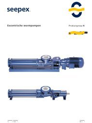
Functions<strong>DMX</strong> <strong>and</strong> <strong>DMH</strong>Overview of functions<strong>DMX</strong> <strong>DMH</strong>Capacity controlStroke-length adjustment • •Operating modesManual control • •Pump types available with electronic control (ver. AR):• <strong>DMX</strong> model 221• <strong>DMX</strong> model 226, up to <strong>and</strong> including a capacity (Q)of 525 l/h.• <strong>DMH</strong> models 251, 252, 253, 280 <strong>and</strong> 281.Capacity controlFig. 5 <strong>DMX</strong> <strong>and</strong> <strong>DMH</strong>GrA1063Q[l/h]TM03 2023 3505l [%]TM03 2097 3705Fig. 6 The capacity is controlled by adjusting thestroke lengthFig. 7 Relation between stroke length <strong>and</strong> capacityFunctional descriptionThe capacity is controlled by means of the strokelengthadjusting knob. The stroke frequency remainsconstant.Capacitysetting100%DischargeDurationSuction50%10%DischargeSuctionDischargeSuctionDurationDurationTM03 2074 3505Fig. 8 Relation between stroke-length adjustment <strong>and</strong> capacity7
Performance curves<strong>DMX</strong> <strong>and</strong> <strong>DMH</strong>Curve conditionsThese guidelines apply to the curves shown below:• The measurements are based on single-headpumps (twin-head pumps have double the flow rateof single-head versions).• Measurements have been made with water; suctionline with foot valve <strong>and</strong> 0.5 m flooded suction.• Zero point of the dosing pump at a counter pressureof 3 bar.• The measurements have been made with a st<strong>and</strong>ardpump version.• Mains frequency = 50 Hz.Q = flow rate [l/h].I = stroke length [%].<strong>DMX</strong><strong>DMX</strong> 4-10<strong>DMX</strong> 8-10Q[l/h]5.0<strong>DMX</strong> 4-10Q[l/h]10<strong>DMX</strong> 8-104.594.083.573.062.52.03 bar10 bar543 bar10 bar1.531.020.50.00 10 20 30 40 50 60 70 80 90 100l [%]TM03 1804 3205100 10 20 30 40 50 60 70 80 90 100l [%]TM03 1805 3205<strong>DMX</strong> 16-10<strong>DMX</strong> 27-10Q[l/h]20<strong>DMX</strong> 16-10Q[l/h]36<strong>DMX</strong> 27-1018161412108643 bar10 bar32282420161283 bar10 bar2400 10 20 30 40 50 60 70 80 90 100l [%]TM03 1806 320500 10 20 30 40 50 60 70 80 90 100l [%]TM03 1807 32058
Performance curves<strong>DMX</strong> <strong>and</strong> <strong>DMH</strong><strong>DMX</strong> 50-10<strong>DMX</strong> 67-10Q[l/h]605550<strong>DMX</strong> 50-10Q[l/h]8070<strong>DMX</strong> 67-104540353025203 bar10 bar605040303 bar10 bar1510500 10 20 30 40 50 60 70 80 90 100l [%]TM03 1808 3205201000 10 20 30 40 50 60 70 80 90 100l [%]TM03 1811 3205<strong>DMX</strong> 75-4Q[l/h]90807060504030201003 bar<strong>DMX</strong> 75-44 bar0 10 20 30 40 50 60 70 80 90 100l [%]TM03 1809 3205<strong>DMX</strong> 100-8Q[l/h]13012011010090807060504030201003 bar<strong>DMX</strong> 100-84 bar0 10 20 30 40 50 60 70 80 90 100l [%]TM03 1994 3505<strong>DMX</strong> 115 3<strong>DMX</strong> 132-10Q[l/h]140120<strong>DMX</strong> 115-3Q[l/h]180160140<strong>DMX</strong> 132-101001208060401.5 bar 3 bar1008060403 bar10 bar2000 10 20 30 40 50 60 70 80 90 100l [%]TM03 1810 32052000 10 20 30 40 50 60 70 80 90 100l [%]TM03 1995 35059
Performance curves<strong>DMX</strong> <strong>and</strong> <strong>DMH</strong><strong>DMX</strong> 460-6<strong>DMX</strong> 525-3Q[l/h]600550<strong>DMX</strong> 460-6Q[l/h]700<strong>DMX</strong> 525-35004504003503003 bar6 bar6005004001.5 bar 3 bar2502001503002001005000 10 20 30 40 50 60 70 80 90 100l [%]TM03 1817 320510000 10 20 30 40 50 60 70 80 90 100l [%]TM03 1818 3205<strong>DMX</strong> 765-3Q[l/h]1000<strong>DMX</strong> 765-390080070060050040030020010001.5 bar 3 bar0 10 20 30 40 50 60 70 80 90 100l [%]TM03 1819 320511
Performance curves<strong>DMX</strong> <strong>and</strong> <strong>DMH</strong><strong>DMH</strong><strong>DMH</strong> 5-10<strong>DMH</strong> 13-10Q[l/h]8<strong>DMH</strong> 5-10Q[l/h]18<strong>DMH</strong> 13-1071665433 bar10 bar141210863 bar10 bar241200 10 20 30 40 50 60 70 80 90 100l [%]TM03 1997 350500 10 20 30 40 50 60 70 80 90 100l [%]TM03 1998 3505<strong>DMH</strong> 24-10<strong>DMH</strong> 37-10Q[l/h]32<strong>DMH</strong> 24-10Q[l/h]45<strong>DMH</strong> 37-102840242016123 bar10 bar35302520153 bar10 bar8104500 10 20 30 40 50 60 70 80 90 100l [%]TM03 1999 350500 10 20 30 40 50 60 70 80 90 100l [%]TM03 2000 3505<strong>DMH</strong> 46-10<strong>DMH</strong> 67-10Q[l/h]555045<strong>DMH</strong> 46-10Q[l/h]8070<strong>DMH</strong> 67-1040603530253 bar10 bar50403 bar10 bar20301510500 10 20 30 40 50 60 70 80 90 100l [%]TM03 2001 3505201000 10 20 30 40 50 60 70 80 90 100l [%]TM03 2002 350512
Performance curves<strong>DMX</strong> <strong>and</strong> <strong>DMH</strong><strong>DMH</strong> 100-10<strong>DMH</strong> 143-10Q[l/h]13012011010090807060504030201003 bar<strong>DMH</strong> 100-1010 bar0 10 20 30 40 50 60 70 80 90 100l [%]TM03 2003 3505Q[l/h]1801601401201008060402003 bar<strong>DMH</strong> 143-1010 bar0 10 20 30 40 50 60 70 80 90 100l [%]TM03 2004 3505<strong>DMH</strong> 213-10<strong>DMH</strong> 291-10Q[l/h]280240<strong>DMH</strong> 213-10Q[l/h]360320280<strong>DMH</strong> 291-10200160120803 bar10 bar240200160120803 bar10 bar404000 10 20 30 40 50 60 70 80 90 100l [%]TM03 2005 350500 10 20 30 40 50 60 70 80 90 100l [%]TM03 2006 3505<strong>DMH</strong> 332-10<strong>DMH</strong> 550-10Q[l/h]400360320<strong>DMH</strong> 332-10Q[l/h]700600<strong>DMH</strong> 550-102805002402001603 bar10 bar4003003 bar10 bar120804020010000 10 20 30 40 50 60 70 80 90 100l [%]TM03 2007 350500 10 20 30 40 50 60 70 80 90 100l [%]TM03 2008 350513
Performance curves<strong>DMX</strong> <strong>and</strong> <strong>DMH</strong><strong>DMH</strong> 770-10<strong>DMH</strong> 1150-10Q[l/h]900<strong>DMH</strong> 770-10Q[l/h]1600<strong>DMH</strong> 1150-1080014007006005004003002003 bar10 bar120010008006004003 bar10 bar10020000 10 20 30 40 50 60 70 80 90 100l [%]TM03 2009 350500 10 20 30 40 50 60 70 80 90 100l [%]TM03 2010 350514
Construction<strong>DMX</strong> <strong>and</strong> <strong>DMH</strong>General descriptionThe Grundfos <strong>DMX</strong> <strong>and</strong> <strong>DMH</strong> pumps are mechanical diaphragmdosing pumps. The strokes are generated by aneccentric which moves the diaphragm by means of aspring-loaded plunger. The discharge stroke is activatedby the eccentric <strong>and</strong> the suction stroke by the spring return.The <strong>DMX</strong> <strong>and</strong> <strong>DMH</strong> pumps are designed for capacitiesbetween 4 <strong>and</strong> 2 x 1150 l/h <strong>and</strong> a maximum pressure upto 200 bar. The <strong>DMX</strong> pumps are fitted with a separationchamber. In the event of a diaphragm failure, the separationchamber prevents the pumped liquid from floodingthe pump unit or other system components.<strong>DMX</strong> model 221174932856TM03 2182 3805Fig. 9 Sectional drawing, <strong>DMX</strong> model 221Functional principle• Reciprocating displacement pump with electric motor<strong>and</strong> mechanical diaphragm control.• The rotation of the motor is transformed into the reciprocatingmovement of the dosing diaphragm by theoperation of the eccentric <strong>and</strong> tappet.• Adjustment of the dosing flow is possible by adjustingthe stroke length.LegendPos. Component1 Motor2 Gears3 Eccentric4 Dosing diaphragm5 Dosing head6 Suction valve7 Discharge valve8 Stroke-length adjusting knob9 Tappet15
Construction<strong>DMX</strong> <strong>and</strong> <strong>DMH</strong><strong>DMX</strong> model 226174932856TM03 1869-3805Fig. 10 Sectional drawing, <strong>DMX</strong> model 226Functional principle• Reciprocating displacement pump with electric motor<strong>and</strong> mechanical diaphragm control.• The rotation of the motor is transformed into the reciprocatingmovement of the dosing diaphragm by theoperation of the eccentric <strong>and</strong> tappet.• Adjustment of the dosing flow is possible by adjustingthe stroke length.LegendPos. Component1 Motor2 Gears3 Eccentric4 Dosing diaphragm5 Dosing head6 Suction valve7 Discharge valve8 Stroke-length adjusting knob9 Tappet16
Construction<strong>DMX</strong> <strong>and</strong> <strong>DMH</strong><strong>DMH</strong> model 251Oscillating positive displacement pumps with hydraulicdiaphragm control.11513871412 11 10 9 6 5 2 3Fig. 11 Sectional drawing, <strong>DMH</strong> model 251TM03 2164 3805Functional principle• The rotational movement of the drive motor (1) is convertedvia the worm gearing (2) <strong>and</strong> eccentric (3) intothe oscillating suction <strong>and</strong> stroke movement of the piston(6).• The piston has a hollow bore <strong>and</strong> a row of radial controlholes, which provide a hydraulic connectionbetween the drive area <strong>and</strong> the piston stroke area.The sliding plug (5) envelops the holes during thestroke <strong>and</strong> seals the stroke area from the drive area.The hydraulic excursion of the solid PTFE diaphragm(10) displaces an equivalent volume of dosing liquidfrom the dosing head (11) into the dosing line. With thesuction stroke, the piston creates a low pressure,which propagates in the dosing head; the ball valve(13) on the dosing side closes <strong>and</strong> the dosing liquidflows through the suction valve (12) into the dosinghead.• The stroke volume size is solely determined by theposition of the sliding plug. The active stroke length<strong>and</strong> corresponding average dosing flow can thereforebe changed continuously <strong>and</strong> linearly from 10 to 100%using the stroke-length adjusting knob <strong>and</strong> Noniusscale (14).LegendPos. Component1 Motor2 Worm gearing3 Eccentric5 Sliding plug6 Piston7 Combined pressure-relief <strong>and</strong> degassing valve8 Oil degassing valve9 Diaphragm protection valve (AMS)10 Dosing diaphragm11 Dosing head12 Suction valve13 Discharge valve14 Stroke-length adjusting knob15 Aeration screw with oil-level gauge17
Construction<strong>DMX</strong> <strong>and</strong> <strong>DMH</strong><strong>DMH</strong> model 252Oscillating positive displacement pumps with hydraulicdiaphragm control.11513871412 11 10 9 6 5 2 3Fig. 12 Sectional drawing, <strong>DMH</strong> model 252TM03 2164 3805Functional principle• The rotational movement of the drive motor (1) is convertedvia the worm gearing (2) <strong>and</strong> eccentric (3) intothe oscillating suction <strong>and</strong> stroke movement of the piston(6).• The piston has a hollow bore <strong>and</strong> a row of radial controlholes, which provide a hydraulic connectionbetween the drive area <strong>and</strong> the piston stroke area.The sliding plug (5) envelops the holes during thestroke <strong>and</strong> seals the stroke area from the drive area.The hydraulic excursion of the solid PTFE diaphragm(10) displaces an equivalent volume of dosing liquidfrom the dosing head (11) into the dosing line. With thesuction stroke, the piston creates a low pressure,which propagates in the dosing head; the ball valve(13) on the dosing side closes <strong>and</strong> the dosing liquidflows through the suction valve (12) into the dosinghead.• The stroke volume size is solely determined by theposition of the sliding plug. The active stroke length<strong>and</strong> corresponding average dosing flow can thereforebe changed continuously <strong>and</strong> linearly from 10 to 100%using the stroke-length adjusting knob <strong>and</strong> Noniusscale (14).LegendPos. Component1 Motor2 Worm gearing3 Eccentric5 Sliding plug6 Piston7 Combined pressure-relief <strong>and</strong> degassing valve8 Oil degassing valve9 Diaphragm protection valve (AMS)10 Dosing diaphragm11 Dosing head12 Suction valve13 Discharge valve14 Stroke-length adjusting knob15 Aeration screw with oil-level gauge18
Construction<strong>DMX</strong> <strong>and</strong> <strong>DMH</strong><strong>DMH</strong> model 253Oscillating positive displacement pumps with hydraulicdiaphragm control.113871514ce12 11 10 9 4 6 5 2 3Fig. 13 Sectional drawing, <strong>DMH</strong> model 253TM03 2165 3805Functional principle• The rotational movement of the drive motor (1) is convertedvia the worm gearing (2) <strong>and</strong> eccentric (3) intothe oscillating suction <strong>and</strong> stroke movement of the piston(6).• The piston has a hollow bore <strong>and</strong> a row of radial controlholes, which provide a hydraulic connectionbetween the drive area <strong>and</strong> the piston stroke area.The sliding plug (5) envelops the holes during thestroke <strong>and</strong> seals the stroke area from the drive area.The hydraulic excursion of the solid PTFE diaphragm(10) displaces an equivalent volume of dosing liquidfrom the dosing head (11) into the dosing line. With thesuction stroke, the piston creates a low pressure,which propagates in the dosing head; the ball valve(13) on the dosing side closes <strong>and</strong> the dosing liquidflows through the suction valve (12) into the dosinghead.• The stroke volume size is solely determined by theposition of the sliding plug. The active stroke length<strong>and</strong> corresponding average dosing flow can thereforebe changed continuously <strong>and</strong> linearly from 10 to 100%using the stroke-length adjusting knob <strong>and</strong> Noniusscale (14).LegendPos. Component1 Motor2 Worm gearing3 Eccentric4 Return spring (some models excluded)5 Sliding plug6 Piston7 Combined pressure-relief <strong>and</strong> degassing valve8 Oil degassing valve9 Diaphragm protection valve (AMS)10 Dosing diaphragm11 Dosing head12 Suction valve13 Discharge valve14 Stroke-length adjusting knob15 Aeration screw with oil-level gauge19
Construction<strong>DMX</strong> <strong>and</strong> <strong>DMH</strong><strong>DMH</strong> model 254Oscillating positive-displacement pumps with hydraulicdiaphragm control.11371514εχ12 11 10 9 4 6 5 2 3Fig. 14 Sectional drawing, <strong>DMH</strong> model 254TM03 2166 3805Functional principle• The rotational movement of the drive motor (1) is convertedvia the worm gearing (2) <strong>and</strong> eccentric (3) intothe oscillating suction <strong>and</strong> stroke movement of the piston(6).• The piston has a hollow bore <strong>and</strong> a row of radial controlholes, which provide a hydraulic connectionbetween the drive area <strong>and</strong> the piston stroke area.The sliding plug (5) envelops the holes during thestroke <strong>and</strong> seals the stroke area from the drive area.The hydraulic excursion of the solid PTFE diaphragm(10) displaces an equivalent volume of dosing liquidfrom the dosing head (11) into the dosing line. With thesuction stroke, the piston creates a low pressure,which propagates in the dosing head; the ball valve(13) on the dosing side closes <strong>and</strong> the dosing liquidflows through the suction valve (12) into the dosinghead.• The stroke volume size is solely determined by theposition of the sliding plug. The active stroke length<strong>and</strong> corresponding average dosing flow can thereforebe changed continuously <strong>and</strong> linearly from 10 to 100%using the stroke-length adjusting knob <strong>and</strong> Noniusscale (14).LegendPos. Component1 Motor2 Worm gearing3 Eccentric4 Return spring (some models excluded)5 Sliding plug6 Piston7 Combined pressure-relief <strong>and</strong> degassing valve9 Diaphragm protection valve (AMS)10 Dosing diaphragm11 Dosing head12 Suction valve13 Discharge valve14 Stroke-length adjusting knob15 Aeration screw with oil-level gauge20
Construction<strong>DMX</strong> <strong>and</strong> <strong>DMH</strong><strong>DMH</strong> model 255Oscillating positive-displacement pumps with hydraulicdiaphragm control.1371151412 11 10 9 4 65 2 3Fig. 15 Sectional drawing, <strong>DMH</strong> model 255TM03 2163 3805Functional principle• The rotational movement of the drive motor (1) is convertedvia the worm gearing (2) <strong>and</strong> eccentric (3) intothe oscillating suction <strong>and</strong> stroke movement of the piston(6).• The piston has a hollow bore <strong>and</strong> a row of radial controlholes, which provide a hydraulic connectionbetween the drive area <strong>and</strong> the piston stroke area.The sliding plug (5) envelops the holes during thestroke <strong>and</strong> seals the stroke area from the drive area.The hydraulic excursion of the solid PTFE diaphragm(10) displaces an equivalent volume of dosing liquidfrom the dosing head (11) into the dosing line. With thesuction stroke, the piston creates a low pressure,which propagates in the dosing head; the ball valve(13) on the dosing side closes <strong>and</strong> the dosing liquidflows through the suction valve (12) into the dosinghead.• The stroke volume size is solely determined by theposition of the sliding plug. The active stroke length<strong>and</strong> corresponding average dosing flow can thereforebe changed continuously <strong>and</strong> linearly from 10 to 100%using the stroke-length adjusting knob <strong>and</strong> Noniusscale (14).LegendPos. Component1 Motor2 Worm gearing3 Eccentric4 Return spring (some models excluded)5 Sliding plug6 Piston7 Combined pressure-relief <strong>and</strong> degassing valve9 Diaphragm protection valve (AMS)10 Dosing diaphragm11 Dosing head12 Suction valve13 Discharge valve14 Stroke-length adjusting knob15 Aeration screw with oil-level gauge21
Construction<strong>DMX</strong> <strong>and</strong> <strong>DMH</strong><strong>DMH</strong> model 257Oscillating positive-displacement pumps with hydraulicdiaphragm control.1137151412 11 10 9 6 5 2 3Fig. 16 Sectional drawing, <strong>DMH</strong> model 257TM03 2162 3805Functional principle• The rotational movement of the drive motor (1) is convertedvia the worm gearing (2) <strong>and</strong> eccentric (3) intothe oscillating suction <strong>and</strong> stroke movement of the piston(6).• The piston has a hollow bore <strong>and</strong> a row of radial controlholes, which provide a hydraulic connectionbetween the drive area <strong>and</strong> the piston stroke area.The sliding plug (5) envelops the holes during thestroke <strong>and</strong> seals the stroke area from the drive area.The hydraulic excursion of the solid PTFE diaphragm(10) displaces an equivalent volume of dosing liquidfrom the dosing head (11) into the dosing line. With thesuction stroke, the piston creates a low pressure,which propagates in the dosing head; the ball valve(13) on the dosing side closes <strong>and</strong> the dosing liquidflows through the suction valve (12) into the dosinghead.• The stroke volume size is solely determined by theposition of the sliding plug. The active stroke length<strong>and</strong> corresponding average dosing flow can thereforebe changed continuously <strong>and</strong> linearly from 10 to 100%using the stroke-length adjusting knob <strong>and</strong> Noniusscale (14).LegendPos. Component1 Motor2 Worm gearing3 Eccentric5 Sliding plug6 Piston7 Combined pressure-relief <strong>and</strong> degassing valve9 Diaphragm protection valve (AMS)10 Dosing diaphragm11 Dosing head12 Suction valve13 Discharge valve14 Stroke-length adjusting knob15 Aeration screw with oil-level gauge22
Construction<strong>DMX</strong> <strong>and</strong> <strong>DMH</strong><strong>DMH</strong> model 280Oscillating positive-displacement pumps with hydraulicdiaphragm control.16138711514εχ12 11 10 9 6 5 2 3Fig. 17 Sectional drawing, <strong>DMH</strong> model 280TM03 2961 5005Functional principle• The rotational movement of the drive motor (1) is convertedvia the worm gearing (2) <strong>and</strong> eccentric (3) intothe oscillating suction <strong>and</strong> stroke movement of thepiston (6).• The piston has a hollow bore <strong>and</strong> a row of radial controlholes, which provide a hydraulic connectionbetween the drive area <strong>and</strong> the piston stroke area.The slide valve (5) envelops the holes during thestroke <strong>and</strong> seals the stroke area from the drive area.The hydraulic excursion of the solid PTFE diaphragm(10) displaces an equivalent volume of dosing liquidfrom the dosing head (11) into the dosing line. Withthe suction stroke, the piston creates a low pressure,which propagates in the dosing head; the ball valve(13) on the dosing side closes <strong>and</strong> the dosing liquidflows through the suction valve (12) into the dosinghead.• The stroke volume size is solely determined by theposition of the slide valve. The active stroke length<strong>and</strong> corresponding average dosing flow can thereforebe changed continuously <strong>and</strong> linearly from 10 to100% using the stroke-length adjusting knob <strong>and</strong>Nonius scale (14).LegendPos. Component1 Motor2 Worm gearing3 Eccentric5 Slide valve6 Piston7 Combined pressure-relief <strong>and</strong> degassing valve8 Oil degassing valve9 Diaphragm-protection valve (AMS)10 Dosing diaphragm11 Dosing head12 Suction valve13 Discharge valve14 Stroke-length adjusting knob15 Aeration screw with oil-level gauge16 Dosing head air vent valve (priming)23
Construction<strong>DMX</strong> <strong>and</strong> <strong>DMH</strong><strong>DMH</strong> model 281Oscillating positive-displacement pumps with hydraulicdiaphragm control.11613871514εχ12 11 10 9 6 5 2 3Fig. 18 Sectional drawing, <strong>DMH</strong> model 281TM03 2962 5005Functional principle• The rotational movement of the drive motor (1) is convertedvia the worm gearing (2) <strong>and</strong> eccentric (3) intothe oscillating suction <strong>and</strong> stroke movement of thepiston (6).• The piston has a hollow bore <strong>and</strong> a row of radial controlholes, which provide a hydraulic connectionbetween the drive area <strong>and</strong> the piston stroke area.The slide valve (5) envelops the holes during thestroke <strong>and</strong> seals the stroke area from the drive area.The hydraulic excursion of the solid PTFE diaphragm(10) displaces an equivalent volume of dosing liquidfrom the dosing head (11) into the dosing line. Withthe suction stroke, the piston creates a low pressure,which propagates in the dosing head; the ball valve(13) on the dosing side closes <strong>and</strong> the dosing liquidflows through the suction valve (12) into the dosinghead.• The stroke volume size is solely determined by theposition of the slide valve. The active stroke length<strong>and</strong> corresponding average dosing flow can thereforebe changed continuously <strong>and</strong> linearly from 10 to100% using the stroke-length adjusting knob <strong>and</strong>Nonius scale (14).LegendPos. Component1 Motor2 Worm gearing3 Eccentric5 Slide valve6 Piston7 Combined pressure-relief <strong>and</strong> degassing valve8 Oil degassing valve9 Diaphragm-protection valve (AMS)10 Dosing diaphragm11 Dosing head12 Suction valve13 Discharge valve14 Stroke-length adjusting knob15 Aeration screw with oil-level gauge16 Dosing head air vent valve (priming)24
Construction<strong>DMX</strong> <strong>and</strong> <strong>DMH</strong><strong>DMH</strong> model 283Oscillating positive-displacement pumps with hydraulicdiaphragm control..1161387151412 11 10 9 6 5 2 3Fig. 19 Sectional drawing, <strong>DMH</strong> model 283TM03 2963 5005Functional principle• The rotational movement of the drive motor (1) is convertedvia the worm gearing (2) <strong>and</strong> eccentric (3) intothe oscillating suction <strong>and</strong> stroke movement of thepiston (6).• The piston has a hollow bore <strong>and</strong> a row of radial controlholes, which provide a hydraulic connectionbetween the drive area <strong>and</strong> the piston stroke area.The slide valve (5) envelops the holes during thestroke <strong>and</strong> seals the stroke area from the drive area.The hydraulic excursion of the solid PTFE diaphragm(10) displaces an equivalent volume of dosing liquidfrom the dosing head (11) into the dosing line. Withthe suction stroke, the piston creates a low pressure,which propagates in the dosing head; the ball valve(13) on the dosing side closes <strong>and</strong> the dosing liquidflows through the suction valve (12) into the dosinghead.• The stroke volume size is solely determined by theposition of the slide valve. The active stroke length<strong>and</strong> corresponding average dosing flow can thereforebe changed continuously <strong>and</strong> linearly from 10 to100% using the stroke-length adjusting knob <strong>and</strong>Nonius scale (14).LegendPos. Component1 Motor2 Worm gearing3 Eccentric5 Slide valve6 Piston7 Combined pressure-relief <strong>and</strong> degassing valve8 Oil degassing valve9 Diaphragm-protection valve (AMS)10 Dosing diaphragm11 Dosing head12 Suction valve13 Discharge valve14 Stroke-length adjusting knob15 Aeration screw with oil-level gauge16 Dosing head air vent valve (priming)25
Construction<strong>DMX</strong> <strong>and</strong> <strong>DMH</strong><strong>DMH</strong> model 285Oscillating positive-displacement pumps with hydraulicdiaphragm control.1161387151412 11 10 9 6 5 2 3Fig. 20 Sectional drawing, <strong>DMH</strong> model 285TM03 2964 5005Functional principle• The rotational movement of the drive motor (1) is convertedvia the worm gearing (2) <strong>and</strong> eccentric (3) intothe oscillating suction <strong>and</strong> stroke movement of thepiston (6).• The piston has a hollow bore <strong>and</strong> a row of radial controlholes, which provide a hydraulic connectionbetween the drive area <strong>and</strong> the piston stroke area.The slide valve (5) envelops the holes during thestroke <strong>and</strong> seals the stroke area from the drive area.The hydraulic excursion of the solid PTFE diaphragm(10) displaces an equivalent volume of dosing liquidfrom the dosing head (11) into the dosing line. Withthe suction stroke, the piston creates a low pressure,which propagates in the dosing head; the ball valve(13) on the dosing side closes <strong>and</strong> the dosing liquidflows through the suction valve (12) into the dosinghead.• The stroke volume size is solely determined by theposition of the slide valve. The active stroke length<strong>and</strong> corresponding average dosing flow can thereforebe changed continuously <strong>and</strong> linearly from 10 to100% using the stroke-length adjusting knob <strong>and</strong>Nonius scale (14).LegendPos. Component1 Motor2 Worm gearing3 Eccentric5 Slide valve6 Piston7 Combined pressure-relief <strong>and</strong> degassing valve8 Oil degassing valve9 Diaphragm-protection valve (AMS)10 Dosing diaphragm11 Dosing head12 Suction valve13 Discharge valve14 Stroke-length adjusting knob15 Aeration screw with oil-level gauge16 Dosing head air vent valve (priming)26
Construction<strong>DMX</strong> <strong>and</strong> <strong>DMH</strong><strong>DMH</strong> model 286Oscillating positive-displacement pumps with hydraulicdiaphragm control.1161387151412 11 10 9 6 5 2 3Fig. 21 Sectional drawing, <strong>DMH</strong> model 286TM03 2964 5005Functional principle• The rotational movement of the drive motor (1) is convertedvia the worm gearing (2) <strong>and</strong> eccentric (3) intothe oscillating suction <strong>and</strong> stroke movement of thepiston (6).• The piston has a hollow bore <strong>and</strong> a row of radial controlholes, which provide a hydraulic connectionbetween the drive area <strong>and</strong> the piston stroke area.The slide valve (5) envelops the holes during thestroke <strong>and</strong> seals the stroke area from the drive area.The hydraulic excursion of the solid PTFE diaphragm(10) displaces an equivalent volume of dosing liquidfrom the dosing head (11) into the dosing line. Withthe suction stroke, the piston creates a low pressure,which propagates in the dosing head; the ball valve(13) on the dosing side closes <strong>and</strong> the dosing liquidflows through the suction valve (12) into the dosinghead.• The stroke volume size is solely determined by theposition of the slide valve. The active stroke length<strong>and</strong> corresponding average dosing flow can thereforebe changed continuously <strong>and</strong> linearly from 10 to100% using the stroke-length adjusting knob <strong>and</strong>Nonius scale (14).LegendPos. Component1 Motor2 Worm gearing3 Eccentric5 Slide valve6 Piston7 Combined pressure-relief <strong>and</strong> degassing valve8 Oil degassing valve9 Diaphragm-protection valve (AMS)10 Dosing diaphragm11 Dosing head12 Suction valve13 Discharge valve14 Stroke-length adjusting knob15 Aeration screw with oil-level gauge16 Dosing head air vent valve (priming)27
Construction<strong>DMX</strong> <strong>and</strong> <strong>DMH</strong><strong>DMH</strong> model 287Oscillating positive-displacement pumps with hydraulicdiaphragm control.1161387151412 11 10 9 6 5 2 3Fig. 22 Sectional drawing, <strong>DMH</strong> model 287TM03 2964 5005Functional principle• The rotational movement of the drive motor (1) is convertedvia the worm gearing (2) <strong>and</strong> eccentric (3) intothe oscillating suction <strong>and</strong> stroke movement of thepiston (6).• The piston has a hollow bore <strong>and</strong> a row of radial controlholes, which provide a hydraulic connectionbetween the drive area <strong>and</strong> the piston stroke area.The slide valve (5) envelops the holes during thestroke <strong>and</strong> seals the stroke area from the drive area.The hydraulic excursion of the solid PTFE diaphragm(10) displaces an equivalent volume of dosing liquidfrom the dosing head (11) into the dosing line. Withthe suction stroke, the piston creates a low pressure,which propagates in the dosing head; the ball valve(13) on the dosing side closes <strong>and</strong> the dosing liquidflows through the suction valve (12) into the dosinghead.• The stroke volume size is solely determined by theposition of the slide valve. The active stroke length<strong>and</strong> corresponding average dosing flow can thereforebe changed continuously <strong>and</strong> linearly from 10 to100% using the stroke-length adjusting knob <strong>and</strong>Nonius scale (14).LegendPos. Component1 Motor2 Worm gearing3 Eccentric5 Slide valve6 Piston7 Combined pressure-relief <strong>and</strong> degassing valve8 Oil degassing valve9 Diaphragm-protection valve (AMS)10 Dosing diaphragm11 Dosing head12 Suction valve13 Discharge valve14 Stroke-length adjusting knob15 Aeration screw with oil-level gauge16 Dosing head air vent valve (priming)28
Construction<strong>DMX</strong> <strong>and</strong> <strong>DMH</strong><strong>DMH</strong> model 288Oscillating positive displacement pumps with hydraulicdiaphragm control.1161387151412 11 10 9 6 5 2 3Fig. 23 Sectional drawing, <strong>DMH</strong> model 288TM03 2965 5005Functional principle• The rotational movement of the drive motor (1) is convertedvia the worm gearing (2) <strong>and</strong> eccentric (3) intothe oscillating suction <strong>and</strong> stroke movement of thepiston (6).• The piston has a hollow bore <strong>and</strong> a row of radial controlholes, which provide a hydraulic connectionbetween the drive area <strong>and</strong> the piston stroke area.The slide valve (5) envelops the holes during thestroke <strong>and</strong> seals the stroke area from the drive area.The hydraulic excursion of the solid PTFE diaphragm(10) displaces an equivalent volume of dosing liquidfrom the dosing head (11) into the dosing line. Withthe suction stroke, the piston creates a low pressure,which propagates in the dosing head; the ball valve(13) on the dosing side closes <strong>and</strong> the dosing liquidflows through the suction valve (12) into the dosinghead.• The stroke volume size is solely determined by theposition of the slide valve. The active stroke length<strong>and</strong> corresponding average dosing flow can thereforebe changed continuously <strong>and</strong> linearly from 10 to100% using the stroke-length adjusting knob <strong>and</strong>Nonius scale (14).LegendPos. Component1 Motor2 Worm gearing3 Eccentric5 Slide valve6 Piston7 Combined pressure-relief <strong>and</strong> degassing valve8 Oil degassing valve9 Diaphragm-protection valve (AMS)10 Dosing diaphragm11 Dosing head12 Suction valve13 Discharge valve14 Stroke-length adjusting knob15 Aeration screw with oil-level gauge16 Dosing head air vent valve (priming)29
Technical data<strong>DMX</strong> <strong>and</strong> <strong>DMH</strong>Dimensions, <strong>DMX</strong> model 221TM03 1731 3605Fig. 24 Dimensions, <strong>DMX</strong> model 221PumpModelA[mm]B[mm]C[mm]C1[mm]D[mm]D1<strong>DMX</strong> 4-10 221 275 319 105 10.5 175 R 5/8 6.5 153 159 102.5 25 32 180 123 179<strong>DMX</strong> 7-10 221 275 319 105 10.5 175 R 5/8 6.5 153 159 102.5 25 32 180 123 179<strong>DMX</strong> 7.2-16 221 275 319 105 10.5 175 R 5/8 6.5 153 159 102.5 25 32 180 123 179<strong>DMX</strong> 8-10 221 275 319 105 10.5 175 R 5/8 6.5 153 159 102.5 25 32 180 123 179<strong>DMX</strong> 9-10 221 275 319 105 10.5 175 R 5/8 6.5 153 159 102.5 25 32 180 123 179<strong>DMX</strong> 12-10 221 275 319 105 10.5 175 R 5/8 6.5 153 159 102.5 25 32 180 123 179<strong>DMX</strong> 13.7-16 221 275 319 105 10.5 175 R 5/8 6.5 153 159 102.5 25 32 180 123 179<strong>DMX</strong> 14-10 221 275 319 105 10.5 175 R 5/8 6.5 153 159 102.5 25 32 180 123 179<strong>DMX</strong> 16-10 221 275 319 105 10.5 175 R 5/8 6.5 153 159 102.5 25 32 180 123 179<strong>DMX</strong> 17-4 221 323 319 105 10.5 175 R 1 1/4 6.5 177 159 102.5 38 64 180 123 192<strong>DMX</strong> 18-10 221 275 319 105 10.5 175 R 5/8 6.5 153 159 102.5 25 32 180 123 179<strong>DMX</strong> 25-3 221 330 319 105 10.5 175 R 1 1/4 6.5 188 159 102.5 40 80 180 123 197<strong>DMX</strong> 26-10 221 275 319 105 10.5 175 R 5/8 6.5 153 159 102.5 25 32 180 123 179<strong>DMX</strong> 27-10 221 275 319 105 10.5 175 R 5/8 6.5 153 159 102.5 25 32 180 123 179<strong>DMX</strong> 35-10 221 275 319 105 10.5 175 R 5/8 6.5 153 159 102.5 25 32 180 123 179<strong>DMX</strong> 39-4 221 323 319 105 10.5 175 R 1 1/4 6.5 177 159 102.5 38 64 180 123 192<strong>DMX</strong> 50-10 221 275 319 105 10.5 175 R 5/8 6.5 153 159 102.5 25 32 180 123 179<strong>DMX</strong> 60-3 221 330 319 105 10.5 175 R 1 1/4 6.5 188 159 102.5 40 80 180 123 197<strong>DMX</strong> 75-4 221 323 319 105 10.5 175 R 1 1/4 6.5 177 159 102.5 38 64 180 123 192<strong>DMX</strong> 115-3 221 330 319 105 10.5 175 R 1 1/4 6.5 188 159 102.5 40 80 180 123 197D2[mm]E[mm]F[mm]G[mm]I[mm]K[mm]M[mm]N[mm]Q[mm]30
Technical data<strong>DMX</strong> <strong>and</strong> <strong>DMH</strong>Dimensions, <strong>DMX</strong> model 226TM03 2086 3605Fig. 25 Dimensions, <strong>DMX</strong> model 226, version MFig. 26 Dimensions, <strong>DMX</strong> model 226, version LPump Model VersionA[mm]B[mm]C[mm]D[mm]D1<strong>DMX</strong> 24-8 226 M 302 310 97.5 190 G 1 1/4 9 178 152 - 85.5 425 104.5 180 180 118 4<strong>DMX</strong> 37-5 226 M 302 310 97.5 190 G 1 1/4 9 178 152 - 85.5 425 104.5 180 180 118 4<strong>DMX</strong> 52-8 226 M 302 310 97.5 190 G 1 1/4 9 178 152 - 85.5 425 104.5 180 180 118 4<strong>DMX</strong> 60-3 226 M 302 310 97.5 190 G 1 1/4 9 178 152 - 85.5 425 104.5 180 180 118 4<strong>DMX</strong> 67-10 226 L 366 372 136 222 G 1 1/4 9 178 140 208 123 440 80 190 258 160 34<strong>DMX</strong> 82-5 226 M 302 310 97.5 190 G 1 1/4 9 178 152 - 85.5 425 104.5 180 180 118 4<strong>DMX</strong> 95-8 226 L 366 372 136 222 G 1 1/4 9 188 140 208 123 444 80 190 258 160 29<strong>DMX</strong> 100-8 226 M 302 310 97.5 190 G 1 1/4 9 178 152 - 85.5 425 104.5 180 180 118 4<strong>DMX</strong> 130-3 226 M 302 310 97.5 190 G 1 1/4 9 178 152 - 85.5 425 104.5 180 180 118 4<strong>DMX</strong> 132-10 226 L 366 372 136 222 G 1 1/4 9 178 140 208 123 440 80 190 258 160 34<strong>DMX</strong> 142-8 226 M 302 310 97.5 190 G 1 1/4 9 178 152 - 85.5 425 104.5 180 180 118 4<strong>DMX</strong> 152-6 226 L - 372 136 222 G 1 1/4 9 208 140 208 123 453 83 190 258 160 19<strong>DMX</strong> 160-5 226 M 302 310 97.5 190 G 1 1/4 9 178 152 - 85.5 425 104.5 180 180 118 4<strong>DMX</strong> 190-8/10 226 L 366 372 136 222 G 1 1/4 9 178 140 208 123 440 80 190 258 160 34<strong>DMX</strong> 199-8 226 L 366 372 136 222 G 1 1/4 9 188 140 208 123 444 80 190 258 160 29<strong>DMX</strong> 230-5 226 M 302 310 97.5 190 G 1 1/4 9 178 152 - 85.5 425 104.5 180 180 118 4<strong>DMX</strong> 249-3 226 L - 390 136 222 G 2 9 240 140 208 123 498 92 190 258 160 3<strong>DMX</strong> 255-3 226 M 302 310 97.5 190 G 1 1/4 9 178 152 - 85.5 425 104.5 180 180 118 4<strong>DMX</strong> 280-6/8 226 L 366 372 136 222 G 1 1/4 9 188 140 208 123 444 80 190 258 160 29<strong>DMX</strong> 315-3 226 L - 390 136 222 G 2 9 240 140 208 123 498 92 190 258 160 3<strong>DMX</strong> 321-4/6 226 L - 372 136 222 G 1 1/4 9 208 140 208 123 453 83 190 258 160 19<strong>DMX</strong> 380-3 226 M 302 310 97.5 190 G 1 1/4 9 178 152 - 85.5 425 104.5 180 180 118 4<strong>DMX</strong> 460-3.5/6 226 L - 372 136 222 G 1 1/4 9 208 140 208 123 453 83 190 258 160 19<strong>DMX</strong> 525-3 226 L - 390 136 222 G 2 9 240 140 208 123 498 92 190 258 160 3<strong>DMX</strong> 765-3 226 L - 390 136 222 G 2 9 240 140 208 123 498 92 190 258 160 3D2[mm]E[mm]F[mm]Fx[mm]G[mm]H[mm]K[mm]M[mm]Mx[mm]N[mm]R[mm]31
Technical data<strong>DMX</strong> <strong>and</strong> <strong>DMH</strong>Dimensions, <strong>DMH</strong> models 251-257TM03 1733 2805Fig. 27 DImensions, <strong>DMH</strong> models 251-257PumpModelA[mm]B[mm]C[mm]D[mm]D1D2[mm]E[mm]<strong>DMH</strong> 2.2-25 251 345 336 97.5 192 R 5/8 9 160 152 152 85.5 432 16 116 180 180 117.5 130.5<strong>DMH</strong> 2.3-16 251 345 336 97.5 192 R 5/8 9 160 152 152 85.5 432 16 116 180 180 117.5 130.5<strong>DMH</strong> 2.4-10 251 345 336 97.5 192 R 5/8 9 160 152 152 85.5 432 16 116 180 180 117.5 130.5<strong>DMH</strong> 4.5-25 251 345 336 97.5 192 R 5/8 9 160 152 152 85.5 432 16 116 180 180 117.5 130.5<strong>DMH</strong> 4.9-16 251 345 336 97.5 192 R 5/8 9 160 152 152 85.5 432 16 116 180 180 117.5 130.5<strong>DMH</strong> 5-10 251 345 336 97.5 192 R 5/8 9 160 152 152 85.5 432 16 116 180 180 117.5 130.5<strong>DMH</strong> 10-16 252 345 336 97.5 192 R 5/8 9 160 152 152 85.5 432 16 116 180 180 117.5 130.5<strong>DMH</strong> 11-10 252 345 336 97.5 192 R 5/8 9 160 152 152 85.5 432 16 116 180 180 117.5 130.5<strong>DMH</strong> 11-25 251 345 336 97.5 192 R 5/8 9 160 152 152 85.5 432 16 116 180 180 117.5 130.5<strong>DMH</strong> 12-16 251 345 336 97.5 192 R 5/8 9 160 152 152 85.5 432 16 116 180 180 117.5 130.5<strong>DMH</strong> 13-10 251 345 336 97.5 192 R 5/8 9 160 152 152 85.5 432 16 116 180 180 117.5 130.5<strong>DMH</strong> 17-25 251 345 336 97.5 192 R 5/8 9 160 152 152 85.5 432 16 116 180 180 117.5 130.5<strong>DMH</strong> 18-16 251 345 336 97.5 192 R 5/8 9 160 152 152 85.5 432 16 116 180 180 117.5 130.5<strong>DMH</strong> 19-10 251 345 336 97.5 192 R 5/8 9 160 152 152 85.5 432 16 116 180 180 117.5 130.5<strong>DMH</strong> 21-10 253 368 336 97.5 192 R 1 1/4 9 179 152 152 85.5 472 13 124 180 180 117.5 130.5<strong>DMH</strong> 21-25 251 345 336 97.5 192 R 5/8 9 160 152 152 85.5 432 16 116 180 180 117.5 130.5<strong>DMH</strong> 23-16 251 345 336 97.5 192 R 5/8 9 160 152 152 85.5 432 16 116 180 180 117.5 130.5<strong>DMH</strong> 23-16 252 345 336 97.5 192 R 5/8 9 160 152 152 85.5 432 16 116 180 180 117.5 130.5<strong>DMH</strong> 24-10 251 345 336 97.5 192 R 5/8 9 160 152 152 85.5 432 16 116 180 180 117.5 130.5<strong>DMH</strong> 24-10 252 345 336 97.5 192 R 5/8 9 160 152 152 85.5 432 16 116 180 180 117.5 130.5<strong>DMH</strong> 36-16 252 345 336 97.5 192 R 5/8 9 160 152 152 85.5 432 16 116 180 180 117.5 130.5<strong>DMH</strong> 37-10 252 345 336 97.5 192 R 5/8 9 160 152 152 85.5 432 16 116 180 180 117.5 130.5<strong>DMH</strong> 43-10 253 368 336 97.5 192 R 1 1/4 9 179 152 152 85.5 472 13 124 180 180 117.5 130.5<strong>DMH</strong> 45-16 252 345 336 97.5 192 R 5/8 9 160 152 152 85.5 432 16 116 180 180 117.5 130.5<strong>DMH</strong> 46-10 252 345 336 97.5 192 R 5/8 9 160 152 152 85.5 432 16 116 180 180 117.5 130.5<strong>DMH</strong> 50-10 254 436 492 156 252 R 1 1/4 9 207 185 260 126 718 10 185 225 300 180 258<strong>DMH</strong> 54-16 252 345 336 97.5 192 R 5/8 9 160 152 152 85.5 432 16 116 180 180 117.5 130.5<strong>DMH</strong> 67-10 253 368 336 97.5 192 R 1 1/4 9 179 152 152 85.5 472 13 124 180 180 117.5 130.5<strong>DMH</strong> 83-10 253 368 336 97.5 192 R 1 1/4 9 179 152 152 85.5 472 13 124 180 180 117.5 130.5<strong>DMH</strong> 97-16 254 436 492 156 252 R 1 1/4 9 207 185 260 126 718 10 185 225 300 180 258<strong>DMH</strong> 100-10 253 368 336 97.5 192 R 1 1/4 9 179 152 152 85.5 472 13 124 180 180 117.5 130.5<strong>DMH</strong> 102-10 254 436 492 156 252 R 1 1/4 9 207 185 260 126 718 10 185 225 300 180 258<strong>DMH</strong> 136-16 254 436 492 156 252 R 1 1/4 9 207 185 260 126 718 10 185 225 300 180 258<strong>DMH</strong> 143-10 254 436 492 156 252 R 1 1/4 9 207 185 260 126 718 10 185 225 300 180 258<strong>DMH</strong> 166-16 254 436 492 156 252 R 1 1/4 9 207 185 260 126 718 10 185 225 300 180 258<strong>DMH</strong> 175-10 254 436 492 156 252 R 1 1/4 9 207 185 260 126 718 10 185 225 300 180 258<strong>DMH</strong> 194-10 255 510 492 156 254 R 1 1/4 9 228 185 260 126 869 10 253 225 300 180 258<strong>DMH</strong> 202-16 254 436 492 156 252 R 1 1/4 9 207 185 260 126 718 10 185 225 300 180 258F[mm]Fx[mm]G[mm]H[mm]J[mm]K[mm]M[mm]Mx[mm]N[mm]X[mm]32
Technical data<strong>DMX</strong> <strong>and</strong> <strong>DMH</strong>PumpModelA[mm]B[mm]C[mm]D[mm]D1D2[mm]E[mm]<strong>DMH</strong> 213-10 254 436 492 156 252 R 1 1/4 9 207 185 260 126 718 10 185 225 300 180 258<strong>DMH</strong> 220-10 257 589 553 170 274 DN 32 9 280 241 333 128.5 980 25 262 290 382 194.5 271<strong>DMH</strong> 270-10 255 510 492 156 254 R 1 1/4 9 228 185 260 126 869 10 253 225 300 180 258<strong>DMH</strong> 276-16 254 436 492 156 252 R 1 1/4 9 207 185 260 126 718 10 185 225 300 180 258<strong>DMH</strong> 291-10 254 436 492 156 252 R 1 1/4 9 207 185 260 126 718 10 185 225 300 180 258<strong>DMH</strong> 332-10 255 510 492 156 254 R 1 1/4 9 228 185 260 126 869 10 253 225 300 180 258<strong>DMH</strong> 403-10 255 510 492 156 254 R 1 1/4 9 228 185 260 126 869 10 253 225 300 180 258<strong>DMH</strong> 440-10 257 589 553 170 274 DN 32 9 280 241 333 128.5 980 25 262 290 382 194.5 271<strong>DMH</strong> 550-10 255 510 492 156 254 R 1 1/4 9 228 185 260 126 869 10 253 225 300 180 258<strong>DMH</strong> 575-10 257 589 553 170 274 DN 32 9 280 241 333 128.5 980 25 262 290 382 194.5 271<strong>DMH</strong> 750-4 257 589 553 170 274 DN 32 9 280 241 333 128.5 980 25 262 290 382 194.5 271<strong>DMH</strong> 770-10 257 589 553 170 274 DN 32 9 280 241 333 128.5 980 25 262 290 382 194.5 271<strong>DMH</strong> 880-10 257 589 553 170 274 DN 32 9 280 241 333 128.5 980 25 262 290 382 194.5 271<strong>DMH</strong> 1150-10 257 589 553 170 274 DN 32 9 280 241 333 128.5 980 25 262 290 382 194.5 271<strong>DMH</strong> 1500-4 257 589 553 170 274 DN 32 9 280 241 333 128.5 980 25 262 290 382 194.5 271F[mm]Fx[mm]G[mm]H[mm]J[mm]K[mm]M[mm]Mx[mm]N[mm]X[mm]33
Technical data<strong>DMX</strong> <strong>and</strong> <strong>DMH</strong>Dimensions, <strong>DMH</strong> models 280-288TM03 2966 5005Fig. 28 DImensions, <strong>DMH</strong> models 280-288PumpModelA[mm]B[mm]C[mm]D[mm]D1D2[mm]E[mm]<strong>DMH</strong> 0.6-200 280 365 336 97.5 192 R 3/8 9 142 152 152 85.5 465 16 114 180 180 117.5 130.5<strong>DMH</strong> 1.3-200 280 365 336 97.5 192 R 3/8 9 142 152 152 85.5 465 16 114 180 180 117.5 130.5<strong>DMH</strong> 2.2-200 280 365 336 97.5 192 R 3/8 9 142 152 152 85.5 465 16 114 180 180 117.5 130.5<strong>DMH</strong> 2.5-200 280 365 336 97.5 192 R 3/8 9 142 152 152 85.5 465 16 114 180 180 117.5 130.5<strong>DMH</strong> 3-200 288 425 492 156 155.5 R 5/8 9 208 185 260 126 700 10 173 225 300 180 258<strong>DMH</strong> 3.3-200 280 365 336 97.5 192 R 3/8 9 142 152 152 85.5 465 16 114 180 180 117.5 130.5<strong>DMH</strong> 4.2-100 281 348 336 97.5 192 R 5/8 9 155 152 152 85.5 432 16 114 180 180 117.5 130.5<strong>DMH</strong> 6.4-100 281 348 336 97.5 192 R 5/8 9 155 152 152 85.5 432 16 114 180 180 117.5 130.5<strong>DMH</strong> 7.5-200 288 425 492 156 155.5 R 5/8 9 208 185 260 126 700 10 173 225 300 180 258<strong>DMH</strong> 8-100 281 348 336 97.5 192 R 5/8 9 155 152 152 85.5 432 16 114 180 180 117.5 130.5<strong>DMH</strong> 9-200 287 490 553 170 274 R 5/8 9 208 240 333 129 814 25 176 290 382 194.5 271<strong>DMH</strong> 9.6-100 281 348 336 97.5 192 R 5/8 9 155 152 152 85.5 432 16 114 180 180 117.5 130.5<strong>DMH</strong> 10-200 288 425 492 156 155.5 R 5/8 9 208 185 260 126 700 10 173 225 300 180 258<strong>DMH</strong> 13-200 288 425 492 156 155.5 R 5/8 9 208 185 260 126 700 10 173 225 300 180 258<strong>DMH</strong> 15-200 288 425 492 156 155.5 R 5/8 9 208 185 260 126 700 10 173 225 300 180 258<strong>DMH</strong> 18-200 287 490 553 170 274 R 5/8 9 208 240 333 129 814 25 176 290 382 194.5 271<strong>DMH</strong> 19-100 283 437 493 156 254 R 1 1/4 9 211 185 260 126 706 10 182 225 300 180 258<strong>DMH</strong> 21-200 288 425 492 156 155.5 R 5/8 9 208 185 260 126 700 10 173 225 300 180 258<strong>DMH</strong> 23-200 287 490 553 170 274 R 5/8 9 208 240 333 129 814 25 176 290 382 194.5 271<strong>DMH</strong> 27-100 283 437 493 156 254 R 1 1/4 9 211 185 260 126 706 10 182 225 300 180 258<strong>DMH</strong> 31-200 287 490 553 170 274 R 5/8 9 208 240 333 129 814 25 176 290 382 194.5 271<strong>DMH</strong> 33-100 283 437 493 156 254 R 1 1/4 9 211 185 260 126 706 10 182 225 300 180 258<strong>DMH</strong> 36-200 287 490 553 170 274 R 5/8 9 208 240 333 129 814 25 176 290 382 194.5 271<strong>DMH</strong> 40-100 283 437 493 156 254 R 1 1/4 9 211 185 260 126 706 10 182 225 300 180 258<strong>DMH</strong> 40-100 285 510 553 145.5 274 R 1 1/4 9 179 240 333 129 820 25 187 290 382 194.5 271<strong>DMH</strong> 50-200 287 490 553 170 274 R 5/8 9 208 240 333 129 814 25 176 290 382 194.5 271<strong>DMH</strong> 52-100 285 510 553 145.5 274 R 1 1/4 9 179 240 333 129 820 25 187 290 382 194.5 271<strong>DMH</strong> 55-100 283 437 493 156 254 R 1 1/4 9 211 185 260 126 706 10 182 225 300 180 258<strong>DMH</strong> 70-100 285 510 553 145.5 274 R 1 1/4 9 179 240 333 129 820 25 187 290 382 194.5 271<strong>DMH</strong> 80-100 285 510 553 145.5 274 R 1 1/4 9 179 240 333 129 820 25 187 290 382 194.5 271<strong>DMH</strong> 85-50 286 510 553 145.5 274 R 1 1/4 9 234 240 333 129 820 25 191 290 382 194.5 271<strong>DMH</strong> 105-100 285 510 553 145.5 274 R 1 1/4 9 179 240 333 129 820 25 187 290 382 194.5 271<strong>DMH</strong> 111-50 286 510 553 145.5 274 R 1 1/4 9 234 240 333 129 820 25 191 290 382 194.5 271<strong>DMH</strong> 170-50 286 510 553 145.5 274 R 1 1/4 9 234 240 333 129 820 25 191 290 382 194.5 271<strong>DMH</strong> 222-50 286 510 553 145.5 274 R 1 1/4 9 234 240 333 129 820 25 191 290 382 194.5 271F[mm]Fx[mm]G[mm]H[mm]J[mm]K[mm]M[mm]Mx[mm]N[mm]X[mm]34
Technical data<strong>DMX</strong> <strong>and</strong> <strong>DMH</strong>Performance data, <strong>DMX</strong> model 221PumpModel1) The maximum flow is measured at maximum counter pressure.2) Maximum counter pressure.3) PTC available for frequency control.*) Operation at a counter pressure of 16 bar reduces diaphragm life.The values in the table above are based on the followingconditions:• dosing liquid: water• flooded suction: 0.5 m• fully vented dosing head• 400 V motor, 3-phase.Vstroke[cm 3 ]Capacity 1)[l/h]50 Hz Motor powerMax. pressure 2)[bar]Stroke rate[n/min]St<strong>and</strong>ard[kW]<strong>DMX</strong> 4-10 221 2.2 4 10 29 0.09 0.09<strong>DMX</strong> 7-10 221 3.8 7 10 29 0.09 0.09<strong>DMX</strong> 7.2-16* 221 1.9 7.2 16 63 0.09 0.18<strong>DMX</strong> 8-10 221 2.2 8 10 63 0.09 0.09<strong>DMX</strong> 9-10 221 4.9 9 10 29 0.09 0.09<strong>DMX</strong> 12-10 221 6.9 12 10 29 0.09 0.18<strong>DMX</strong> 13.7-16* 221 1.9 13.7 16 120 0.09 0.18<strong>DMX</strong> 14-10 221 3.8 14 10 63 0.09 0.09<strong>DMX</strong> 16-10 221 2.2 16 10 120 0.09 -<strong>DMX</strong> 17-4 221 10.4 17 4 29 0.09 0.18<strong>DMX</strong> 18-10 221 4.9 18 10 63 0.09 0.09<strong>DMX</strong> 25-3 221 16 27 3 29 0.09 0.18<strong>DMX</strong> 26-10 221 6.9 26 10 63 0.09 0.18<strong>DMX</strong> 27-10 221 3.8 27 10 120 0.09 -<strong>DMX</strong> 35-10 221 4.9 35 10 120 0.09 -<strong>DMX</strong> 39-4 221 10.4 39 4 63 0.09 0.18<strong>DMX</strong> 50-10 221 6.9 50 10 120 0.09 -<strong>DMX</strong> 60-3 221 16 60 3 63 0.09 0.18<strong>DMX</strong> 75-4 221 10.4 75 4 120 0.09 -<strong>DMX</strong> 115-3 221 16 115 3 120 0.09 -PTC 3)[kW]Minimum counter pressure: 1 bar.The counter pressure refers to the pressure at thepump discharge valve. Pressure losses in the line to theinjection point are not taken into account.35
Technical data<strong>DMX</strong> <strong>and</strong> <strong>DMH</strong>Performance data, <strong>DMX</strong> model 226PumpModelVstroke[cm 3 ]1) 2)Capacity[l/h]Max. pressure 3)3-phase[bar]1) The maximum flow is measured at maximum counter pressure.2) The capacity is per dosing head.(Twin-head pumps have double the flow rate of single-head versions.)3) Maximum counter pressure.4) Motor for frequency control.50 Hz Motor powerMax. pressure 3)1-phase[bar]Stroke rate[n/min]St<strong>and</strong>ard[kW]<strong>DMX</strong> 24-8 226 13.8 24 8 8 29 0.18 -<strong>DMX</strong> 37-5 226 22 37 5 5 29 0.18 -<strong>DMX</strong> 52-8 226 13.8 52 8 8 63 0.18 -<strong>DMX</strong> 60-3 226 36 60 3 3 29 0.18 -<strong>DMX</strong> 67-10 226 18.5 67 10 10 57 0.37 0.55<strong>DMX</strong> 82-5 226 22 82 5 5 63 0.18 -<strong>DMX</strong> 95-8 226 27.8 95 8 8 57 0.37 0.55<strong>DMX</strong> 100-8 226 13.8 100 8 8 120 0.18 -<strong>DMX</strong> 130-3 226 36 130 3 3 63 0.18 -<strong>DMX</strong> 132-10 226 18.5 132 10 10 120 0.37 0.55<strong>DMX</strong> 142-8 226 13.8 142 8 8 168 0.18 -<strong>DMX</strong> 152-6 226 44.6 152 6 6 57 0.37 0.55<strong>DMX</strong> 160-5 226 22 160 5 5 120 0.18 -<strong>DMX</strong> 190-8/10 226 18.5 190 10 8 175 0.37 0.55<strong>DMX</strong> 199-8 226 27.8 199 8 8 120 0.37 0.55<strong>DMX</strong> 230-5 226 22 224 5 5 168 0.18 -<strong>DMX</strong> 249-3 226 73 249 3 3 57 0.37 0.55<strong>DMX</strong> 255-3 226 36 255 3 3 120 0.18 -<strong>DMX</strong> 280-6/8 226 27.8 280 8 6 175 0.37 0.55<strong>DMX</strong> 315-3 226 73 315 3 3 72 0.37 0.55<strong>DMX</strong> 321-4/6 226 44.6 321 6 4 120 0.37 0.55<strong>DMX</strong> 380-3 226 36 380 3 3 168 0.18 -<strong>DMX</strong> 460-3.5/6 226 44.6 460 6 3.5 175 0.37 0.55<strong>DMX</strong> 525-3 226 73 525 3 3 120 0.37 0.55<strong>DMX</strong> 765-3 226 73 765 3 - 175 0.37 0.55PTC 4)[kW]The values in the table above are based on the followingconditions:• maximum counter pressure• dosing liquid: water• flooded suction: 0.5 m• fully vented dosing head• 400 V, 3-phase motor.36
Technical data<strong>DMX</strong> <strong>and</strong> <strong>DMH</strong>Performance data, <strong>DMH</strong> models 251-257PumpModelVstroke[cm 3 ]Pmax 1)[bar]2) 3)Capacity[l/h]1) Maximum counter pressure.2) The maximum capacity is measured at the maximum counter pressure.3) The capacity is per dosing head.50 Hz 60 Hz 100 Hz Motor powerStrokerate[n/min]2) 3)Capacity[l/h]Strokerate[n/min]2) 3)Capacity[l/h]Strokerate[n/min]St<strong>and</strong>ard[kW]<strong>DMH</strong> 2.2-25 251 3.5 25 2.2 14 2.6 17 4.4 29 0.09 0.18<strong>DMH</strong> 2.3-16 251 3.5 16 2.3 14 2.8 17 4.5 29 0.06 0.09<strong>DMH</strong> 2.4-10 251 3.5 10 2.4 14 2.9 17 5 29 0.06 0.09<strong>DMH</strong> 4.5-25 251 3.5 25 4.5 29 5.4 35 9 58 0.09 0.18<strong>DMH</strong> 4.9-16 251 3.5 16 4.9 29 5.9 35 9.8 58 0.06 0.09<strong>DMH</strong> 5-10 251 3.5 10 5 29 6 35 10 58 0.06 0.09<strong>DMH</strong> 10-16 252 6.4 16 10 29 12 35 20 58 0.09 0.18<strong>DMH</strong> 11-10 252 6.4 10 11 29 13 35 22 58 0.09 0.18<strong>DMH</strong> 11-25 251 3.5 25 11 63 13 75 22 126 0.09 0.18<strong>DMH</strong> 12-16 251 3.5 16 12 63 14 75 24 126 0.06 0.09<strong>DMH</strong> 13-10 251 3.5 10 13 63 16 75 25 126 0.06 0.09<strong>DMH</strong> 17-25 251 3.5 25 17 96 20 115 - - 0.09 -<strong>DMH</strong> 18-16 251 3.5 16 18 96 22 115 - - 0.06 -<strong>DMH</strong> 19-10 251 3.5 10 19 96 23 115 - - 0.06 -<strong>DMH</strong> 21-10 253 11.3 10 21 29 25 35 46 58 0.18 0.18<strong>DMH</strong> 21-25 251 3.5 25 21 120 - - - - 0.09 -<strong>DMH</strong> 23-16 251 3.5 16 23 120 - - - - 0.06 -<strong>DMH</strong> 23-16 252 6.4 16 23 63 27 75 46 126 0.09 0.18<strong>DMH</strong> 24-10 251 3.5 10 24 120 - - - - 0.06 -<strong>DMH</strong> 24-10 252 6.4 10 24 63 29 75 48 126 0.09 0.18<strong>DMH</strong> 36-16 252 6.4 16 36 96 43 115 - - 0.09 -<strong>DMH</strong> 37-10 252 6.4 10 37 96 44 115 - - 0.09 -<strong>DMH</strong> 43-10 253 11.3 10 43 63 52 75 87 126 0.18 0.18<strong>DMH</strong> 45-16 252 6.4 16 45 120 - - - - 0.09 -<strong>DMH</strong> 46-10 252 6.4 10 46 120 - - - - 0.09 -<strong>DMH</strong> 50-10 254 31.6 10 50 26 60 31 101 52 0.55 0.55<strong>DMH</strong> 54-16 252 6.4 16 54 144 - - - - 0.09 -<strong>DMH</strong> 67-10 253 11.3 10 67 96 78 115 - - 0.18 -<strong>DMH</strong> 83-10 253 11.3 10 83 120 99 144 - - 0.18 -<strong>DMH</strong> 97-16 254 31.6 16 97 54 116 65 193 108 0.55 0.55<strong>DMH</strong> 100-10 253 11.3 10 100 144 - - - - 0.18 -<strong>DMH</strong> 102-10 254 31.6 10 102 54 122 65 203 108 0.55 0.55<strong>DMH</strong> 136-16 254 31.6 16 136 75 163 90 271 150 0.55 0.55<strong>DMH</strong> 143-10 254 31.6 10 143 75 172 90 286 150 0.55 0.55<strong>DMH</strong> 166-16 254 31.6 16 166 92 200 110 - - 0.55 -<strong>DMH</strong> 175-10 254 31.6 10 175 92 210 110 - - 0.55 -<strong>DMH</strong> 194-10 255 60 10 194 54 233 65 387 108 0.55 0.55<strong>DMH</strong> 202-16 254 31.6 16 202 112 242 134 - - 0.55 -<strong>DMH</strong> 213-10 254 31.6 10 213 112 255 134 - - 0.55 -<strong>DMH</strong> 220-10 257 131 10 220 28 264 34 440 56 1.1 1.5(2.2*)<strong>DMH</strong> 270-10 255 60 10 270 75 324 90 540 150 0.55 0.75<strong>DMH</strong> 276-16 254 31.6 16 276 153 - - - - 0.55 -<strong>DMH</strong> 291-10 254 31.6 10 291 153 - - - - 0.55 -<strong>DMH</strong> 332-10 255 60 10 332 92 398 110 - - 0.55 -<strong>DMH</strong> 403-10 255 60 10 403 112 484 134 - - 0.55 -<strong>DMH</strong> 440-10 257 131 10 440 56 528 67 880 112 1.1 2.2<strong>DMH</strong> 550-10 255 60 10 550 153 - - - - 0.55 2.2<strong>DMH</strong> 575-10 257 131 10 575 73 690 88 1150 146 1.1 2.2<strong>DMH</strong> 750-4 257 171 4 750 73 900 88 1500 146 1.1 2.2<strong>DMH</strong> 770-10 257 131 10 770 98 924 118 - - 1.1 2.2<strong>DMH</strong> 880-10 257 131 10 880 112 1056 134 - - 1.1 2.2<strong>DMH</strong> 1150-10 257 131 10 1150 146 - - - - 1.1 (1.5*) 2.2<strong>DMH</strong> 1500-4 257 171 4 1500 146 - - - - 1.1 2.2PTC 4)[kW](Twin-head pumps have double the flow rate of single-head versions.)4) Motor for frequency control.* For twin-head pumps.37
Technical data<strong>DMX</strong> <strong>and</strong> <strong>DMH</strong>Performance data, <strong>DMH</strong> models 280-288PumpModelVstroke[cm 3 ]Pmax 1)[bar]2) 3)Capacity[l/h]1) Maximum counter pressure.2) The maximum capacity is measured at the maximum counter pressure.3) The capacity is per dosing head.(Twin-head pumps have double the flow rate of single-head versions.)4) Motor for frequency control.* For twin-head pumps.50 Hz 60 Hz 100 Hz Motor powerStrokerate[n/min]2) 3)Capacity[l/h]Strokerate[n/min]2) 3)Capacity[l/h]Strokerate[n/min]St<strong>and</strong>ard[kW]<strong>DMH</strong> 0.6-200 280 0.36 200 0.63 29 0.76 35 1.26 58 0.18 0.18<strong>DMH</strong> 1.3-200 280 0.36 200 1.45 63 1.74 76 2.9 126 0.18 0.18<strong>DMH</strong> 2.2-200 280 0.36 200 2.22 96 2.66 115 - - 0.18 0.18<strong>DMH</strong> 2.5-200 280 0.36 200 2.81 120 3.37 144 - - 0.18 0.18<strong>DMH</strong> 3-200 288 2.33 200 3.6 26 4.3 31 - - 0.55 0.55<strong>DMH</strong> 3.3-200 280 0.36 200 3.41 144 - - - - 0.18 0.18<strong>DMH</strong> 4.2-100 281 1.1 100 4.2 63 5 76 8.2 126 0.18 0.18<strong>DMH</strong> 6.4-100 281 1.1 100 6.4 96 7.7 115 - - 0.18 0.18<strong>DMH</strong> 7.5-200 288 2.33 200 7.5 54 9 65 15 108 0.55 0.55<strong>DMH</strong> 8-100 281 1.1 100 8 120 9.6 144 - - 0.18 0.18<strong>DMH</strong> 9-200 287 6 200 9 28 11 34 - - 1.1 1.5<strong>DMH</strong> 9.6-100 281 1.1 100 9.6 144 - - - - 0.18 0.18<strong>DMH</strong> 10-200 288 2.33 200 10.4 75 12.5 90 21 150 0.55 0.55<strong>DMH</strong> 13-200 288 2.33 200 12.8 92 15.4 118 - - 0.55 0.55<strong>DMH</strong> 15-200 288 2.33 200 15.5 112 18.6 134 - - 0.55 0.55<strong>DMH</strong> 18-200 287 6 200 18 56 22 67 36 112 1.1 1.5<strong>DMH</strong> 19-100 283 6 100 19 54 23 65 38 108 0.55 0.55<strong>DMH</strong> 21-200 288 2.33 200 21 153 - - - - 0.55 0.55<strong>DMH</strong> 23-200 287 6 200 23 73 28 88 46 146 1.1 1.5<strong>DMH</strong> 27-100 283 6 100 27 75 32 90 54 150 0.55 0.55<strong>DMH</strong> 31-200 287 6 200 31 98 37 118 - - 1.1 1.5<strong>DMH</strong> 33-100 283 6 100 33 92 40 110 - - 0.55 0.55<strong>DMH</strong> 36-200 287 6 200 36 112 43 134 - - 1.1 1.5<strong>DMH</strong> 40-100 283 6 100 40 112 48 134 - - 0.55 0.55<strong>DMH</strong> 40-100 285 12 100 40 56 48 67 80 112 1.1 1.5<strong>DMH</strong> 50-200 287 6 200 50 146 - - - - 1.1 1.5<strong>DMH</strong> 52-100 285 12 100 52 73 63 88 105 146 1.1 1.5<strong>DMH</strong> 55-100 283 6 100 55 153 - - - - 0.55 0.55<strong>DMH</strong> 70-100 285 12 100 70 98 84 118 - - 1.1 1.5<strong>DMH</strong> 80-100 285 12 100 80 112 96 134 - - 1.1 1.5<strong>DMH</strong> 85-50 286 25.3 50 85 56 102 67.2 170 112 1.1 1.5<strong>DMH</strong> 105-100 285 12 100 105 146 - - - - 1.1 1.5<strong>DMH</strong> 111-50 286 25.3 50 111 73 133 87.6 222 146 1.1 1.5<strong>DMH</strong> 170-50 286 25.3 50 170 112 204 134 - - 1.1 1.5<strong>DMH</strong> 222-50 286 25.3 50 222 146 - - - - 1.1 1.5PTC 4)[kW]38
Technical data<strong>DMX</strong> <strong>and</strong> <strong>DMH</strong>Suction lift, <strong>DMX</strong> model 221PumpModelContinuous operation1)[m]Liquids with a viscosity similar to waterSuctíon lift - 50 HzStart-up 2)[m]1) Suction line <strong>and</strong> dosing head filled (continuous operation).2) Suction line <strong>and</strong> dosing head not filled, but dosing head <strong>and</strong> valvesmoistened (commissioning).3) Flooded suction.Max. length of suctionline[m]Liquids with max. permissible viscosityMax. permissibleviscosity[mPa s]Suction lift[m]<strong>DMX</strong> 4-10 221 4 4 5 400 1<strong>DMX</strong> 7-10 221 4 4 5 400 1<strong>DMX</strong> 7.2-16* 221 4 4 5 400 1<strong>DMX</strong> 8-10 221 4 4 5 400 1<strong>DMX</strong> 9-10 221 3 4 4 200 1<strong>DMX</strong> 12-10 221 3 4 4 200 1<strong>DMX</strong> 13.7-16* 221 4 4 5 200 1<strong>DMX</strong> 14-10 221 4 4 5 400 1<strong>DMX</strong> 16-10 221 4 4 5 200 1<strong>DMX</strong> 17-4 221 1 3 2 200 1 3)<strong>DMX</strong> 18-10 221 3 4 4 200 1<strong>DMX</strong> 25-3 221 1 1 2 200 1 3)<strong>DMX</strong> 26-10 221 3 4 4 200 1 3)<strong>DMX</strong> 27-10 221 4 4 5 200 1<strong>DMX</strong> 35-10 221 3 4 4 100 1<strong>DMX</strong> 39-4 221 1 3 2 100 1<strong>DMX</strong> 50-10 221 3 4 4 100 1<strong>DMX</strong> 60-3 221 1 1 2 100 1<strong>DMX</strong> 75-4 221 1 3 2 100 1 3)<strong>DMX</strong> 115-3 221 1 1 2 100 1 3)*) Operation at a counter pressure of 16 bar reduces diaphragm life.The values in the table above are based on the followingconditions:Liquids with a viscosity similar to water:• counter pressure: 1.5 to 3 bar• non-degassing <strong>and</strong> non-abrasive liquids• temperature: 20 °C• stroke length: 100%.Liquids with max. permissible viscosity:• newtonian liquids• non-degassing <strong>and</strong> non-abrasive liquids• temperature: 20°C• st<strong>and</strong>ard pump version.39
Technical data<strong>DMX</strong> <strong>and</strong> <strong>DMH</strong>Suction lift, <strong>DMX</strong> model 226PumpModelContinuous operation1)[m]Liquids with a viscosity similar to waterSuctíon lift - 50 HzStart-up 2)[m]1) Suction line <strong>and</strong> dosing head filled (continuous operation).2) Suction line <strong>and</strong> dosing head not filled, but dosing head <strong>and</strong> valvesmoistened (commissioning).Max. length of suctionline[m]Liquids with max. permissible viscosityMax. permissibleviscosity[mPa s]Suction lift[m]<strong>DMX</strong> 24-8 226 3 1 4 1000 1<strong>DMX</strong> 37-5 226 3 1 3 600 1<strong>DMX</strong> 52-8 226 3 1 4 700 1<strong>DMX</strong> 60-3 226 2 1 3 500 1<strong>DMX</strong> 67-10 226 3 1 4 700 1<strong>DMX</strong> 82-5 226 3 1 3 500 1<strong>DMX</strong> 95-8 226 3 1 3 500 1<strong>DMX</strong> 100-8 226 3 1 4 400 1<strong>DMX</strong> 130-3 226 2 1 3 400 0<strong>DMX</strong> 132-10 226 3 1 4 400 1<strong>DMX</strong> 142-8 226 3 1 4 200 0<strong>DMX</strong> 152-6 226 2 1 3 400 0<strong>DMX</strong> 160-5 226 3 1 3 200 0<strong>DMX</strong> 190-8/10 226 3 1 4 200 0<strong>DMX</strong> 199-8 226 3 1 3 200 0<strong>DMX</strong> 230-5 226 3 1 3 150 0<strong>DMX</strong> 249-3 226 1.5 1 2 100 0<strong>DMX</strong> 255-3 226 2 1 3 100 0<strong>DMX</strong> 280-6/8 226 3 1 3 150 0<strong>DMX</strong> 315-3 226 1.5 1 2 100 0<strong>DMX</strong> 321-4/6 226 2 1 3 100 0<strong>DMX</strong> 380-3 226 2 1 3 50 0<strong>DMX</strong> 460-3.5/6 226 2 1 3 50 0<strong>DMX</strong> 525-3 226 1 0.5 2 50 0<strong>DMX</strong> 765-3 226 0 0 2 10 0The values in the table above are based on the followingconditions:Liquids with a viscosity similar to water:• counter pressure: 1.5 to 3 bar• non-degassing <strong>and</strong> non-abrasive liquids• temperature: 20°C• stroke length: 100%• st<strong>and</strong>ard pump version.Liquids with max. permissible viscosity:• newtonian liquids• non-degassing <strong>and</strong> non-abrasive liquids• temperature: 20°C• st<strong>and</strong>ard pump version.40
Technical data<strong>DMX</strong> <strong>and</strong> <strong>DMH</strong>Suction lift, <strong>DMH</strong> models 251-257PumpModelLiquids with aviscositysimilar to water[m]Max. suction liftLiquids withmax.permissibleviscosity[m]Max. inletpressure[bar]Min. counterpressure at thepump pressurevalve[bar]Max. permissible viscosity at operatingtemperature 1)[mPa s]0 to 63strokes/min64 to 120strokes/min120 <strong>and</strong> abovestrokes/min<strong>DMH</strong> 2.2-25 251 1 0★ 8 2 300 100 50<strong>DMH</strong> 2.3-16 251 1 ★0 8 2 300 100 50<strong>DMH</strong> 2.4-10 251 1 0★ 8 2 300 100 50<strong>DMH</strong> 4.5-25 251 1 ★0 8 2 300 100 50<strong>DMH</strong> 4.9-16 251 1 0★ 8 2 300 100 50<strong>DMH</strong> 5-10 251 1 ★0 8 2 300 100 50<strong>DMH</strong> 10-16 252 1 ★0 8 2 300 100 50<strong>DMH</strong> 11-10 252 1 ★0 8 2 300 100 50<strong>DMH</strong> 11-25 251 1 ★0 8 2 300 100 50<strong>DMH</strong> 12-16 251 1 0★ 8 2 300 100 50<strong>DMH</strong> 13-10 251 1 ★0 8 2 300 100 50<strong>DMH</strong> 17-25 251 1 0★ 8 2 300 100 50<strong>DMH</strong> 18-16 251 1 ★0 8 2 300 100 50<strong>DMH</strong> 19-10 251 1 0★ 8 2 300 100 50<strong>DMH</strong> 21-10 253 1 ★0 5 2 300 100 10<strong>DMH</strong> 21-25 251 1 ★0 8 2 300 100 50<strong>DMH</strong> 23-16 251 1 ★0 8 2 300 100 50<strong>DMH</strong> 23-16 252 1 ★0 8 2 300 100 50<strong>DMH</strong> 24-10 251 1 ★0 8 2 300 100 50<strong>DMH</strong> 24-10 252 1 ★0 8 2 300 100 50<strong>DMH</strong> 36-16 252 1 0★ 8 2 300 100 50<strong>DMH</strong> 37-10 252 1 ★0 8 2 300 100 50<strong>DMH</strong> 43-10 253 1 0★ 5 2 300 100 10<strong>DMH</strong> 45-16 252 1 ★0 8 2 300 100 50<strong>DMH</strong> 46-10 252 1 0★ 8 2 300 100 50<strong>DMH</strong> 50-10 254 1 ★0 5 2 300 100 5<strong>DMH</strong> 54-16 252 1 ★0 8 2 300 100 50<strong>DMH</strong> 67-10 253 1 ★0 5 2 300 100 10<strong>DMH</strong> 83-10 253 1 ★0 5 2 300 100 10<strong>DMH</strong> 97-16 254 1 0★ 5 2 300 100 5<strong>DMH</strong> 100-10 253 0 ★ ★0 5 2 300 100 10<strong>DMH</strong> 102-10 254 1 0★ 5 2 300 100 5<strong>DMH</strong> 136-16 254 1 ★0 5 2 300 100 5<strong>DMH</strong> 143-10 254 1 0★ 5 2 300 100 5<strong>DMH</strong> 166-16 254 1 ★0 5 2 300 100 5<strong>DMH</strong> 175-10 254 1 0★ 5 2 300 100 5<strong>DMH</strong> 194-10 255 0 ★ ★0 0.8 2 200 100 5<strong>DMH</strong> 202-16 254 1 ★0 5 2 300 100 5<strong>DMH</strong> 213-10 254 1 ★0 5 2 300 100 5<strong>DMH</strong> 220-10 257 1 ★0 0.8 2 200 50 5<strong>DMH</strong> 270-10 255 0 ★ 0★ 0.8 2 200 100 5<strong>DMH</strong> 276-16 254 0 ★ ★0 5 2 300 100 5<strong>DMH</strong> 291-10 254 0 ★ 0★ 5 2 300 100 5<strong>DMH</strong> 332-10 255 0 ★ ★0 0.8 2 200 100 5<strong>DMH</strong> 403-10 255 0 ★ 0★ 0.8 2 200 100 541
Technical data<strong>DMX</strong> <strong>and</strong> <strong>DMH</strong>PumpModelLiquids with aviscositysimilar to water[m]Max. suction liftLiquids withmax.permissibleviscosity[m]<strong>DMH</strong> 440-10 257 1 ★0 0.8 2 200 50 5<strong>DMH</strong> 550-10 255 0 ★ 0★ 0.8 2 200 100 5<strong>DMH</strong> 575-10 257 1 ★0 0.8 2 200 50 5<strong>DMH</strong> 750-4 257 0 ★ 0★ 0.8 2 200 50 5<strong>DMH</strong> 770-10 257 1 ★0 0.8 2 200 50 5<strong>DMH</strong> 880-10 257 0 ★ 0★ 0.8 2 200 50 5<strong>DMH</strong> 1150-10 257 0 ★ ★0 0.8 2 200 50 5<strong>DMH</strong> 1500-4 257 0 ★ 0★ 0.8 2 200 50 51) Approximate values applying to the st<strong>and</strong>ard version of pumps.Max. inletpressure[bar]Min. counterpressure at thepump pressurevalve[bar]Max. permissible viscosity at operatingtemperature 1)[mPa s]0 to 63strokes/min64 to 120strokes/min120 <strong>and</strong> abovestrokes/minThe values refer to dosing liquids with the following characteristics:- newtonian- non-degassing- not containing suspended matter- density similar to water.*) Flooded suctionNote: The viscosity increases when the temperature decreases.42
Technical data<strong>DMX</strong> <strong>and</strong> <strong>DMH</strong>Suction lift, <strong>DMH</strong> models 280-288PumpModelLiquids with aviscositysimilar to water[m]Max. suction liftLiquids withmax.permissibleviscosity[m]1) Approximate values applying to the st<strong>and</strong>ard version of pumps.Max. inletpressure[bar]Min. counterpressure at thepump pressurevalve[bar]Max. permissible viscosity at operatingtemperature 1)[mPa s]0 to 63strokes/min64 to 120strokes/min120 <strong>and</strong> abovestrokes/min<strong>DMH</strong> 0.6-200 280 0 ★ 0 ★ 1 2 5 5 5<strong>DMH</strong> 1.3-200 280 0 ★ 0 ★ 1 2 5 5 5<strong>DMH</strong> 2.2-200 280 0 ★ 0 ★ 1 2 5 5 5<strong>DMH</strong> 2.5-200 280 0 ★ 0 ★ 1 2 5 5 5<strong>DMH</strong> 3-200 288 1 0★ 5 2 100 50 5<strong>DMH</strong> 3.3-200 280 0 ★ 0 ★ 1 2 5 5 5<strong>DMH</strong> 4.2-100 281 1 ★0 10 2 100 50 5<strong>DMH</strong> 6.4-100 281 1 ★0 10 2 100 50 5<strong>DMH</strong> 7.5-200 288 1 ★0 5 2 100 50 5<strong>DMH</strong> 8-100 281 1 0★ 10 2 100 50 5<strong>DMH</strong> 9-200 287 1 ★0 5 2 100 50 5<strong>DMH</strong> 9.6-100 281 1 0★ 10 2 100 50 5<strong>DMH</strong> 10-200 288 1 ★0 5 2 100 50 5<strong>DMH</strong> 13-200 288 1 0★ 5 2 100 50 5<strong>DMH</strong> 15-200 288 1 ★0 5 2 100 50 5<strong>DMH</strong> 18-200 287 1 ★0 5 2 100 50 5<strong>DMH</strong> 19-100 283 1 ★0 5 2 100 50 5<strong>DMH</strong> 21-200 288 1 ★0 5 2 100 50 5<strong>DMH</strong> 23-200 287 1 ★0 5 2 100 50 5<strong>DMH</strong> 27-100 283 1 ★0 5 2 100 50 5<strong>DMH</strong> 31-200 287 1 0★ 5 2 100 50 5<strong>DMH</strong> 33-100 283 1 ★0 5 2 100 50 5<strong>DMH</strong> 36-200 287 1 0★ 5 2 100 50 5<strong>DMH</strong> 40-100 283 1 ★0 5 2 100 50 5<strong>DMH</strong> 40-100 285 1 0★ 5 2 100 50 5<strong>DMH</strong> 50-200 287 1 ★0 5 2 100 50 5<strong>DMH</strong> 52-100 285 1 ★0 5 2 100 50 5<strong>DMH</strong> 55-100 283 1 ★0 5 2 100 50 5<strong>DMH</strong> 70-100 285 1 ★0 5 2 100 50 5<strong>DMH</strong> 80-100 285 1 0★ 5 2 100 50 5<strong>DMH</strong> 85-50 286 1 ★0 5 2 100 50 5<strong>DMH</strong> 105-100 285 1 0★ 5 2 100 50 5<strong>DMH</strong> 111-50 286 1 ★0 5 2 100 50 5<strong>DMH</strong> 170-50 286 1 0★ 5 2 100 50 5<strong>DMH</strong> 222-50 286 1 ★0 5 2 100 50 5The values refer to dosing liquids with the following characteristics:- newtonian- non-degassing- not containing suspended matter- density similar to water.*) Flooded suctionNote: The viscosity increases when the temperature decreases.43
Technical data<strong>DMX</strong> <strong>and</strong> <strong>DMH</strong>Weights, <strong>DMX</strong> model 221WeightsPump[kg]PlasticsStainless steel<strong>DMX</strong> 4-10 5 7<strong>DMX</strong> 7-10 5 7<strong>DMX</strong> 7,2-16 5 7<strong>DMX</strong> 8-10 5 7<strong>DMX</strong> 9-10 5 7<strong>DMX</strong> 12-10 5 7<strong>DMX</strong> 13,7-16 5 7<strong>DMX</strong> 14-10 5 7<strong>DMX</strong> 16-10 5 7<strong>DMX</strong> 17-4 7,5 12<strong>DMX</strong> 18-10 5 7<strong>DMX</strong> 25-3 8 13<strong>DMX</strong> 26-10 5 7<strong>DMX</strong> 27-10 5 7<strong>DMX</strong> 35-10 5 7<strong>DMX</strong> 39-4 7,5 12<strong>DMX</strong> 50-10 5 7<strong>DMX</strong> 60-3 8 13<strong>DMX</strong> 75-4 7,5 12<strong>DMX</strong> 115-3 8 13The weights are approximate.Weights, <strong>DMX</strong> model 226PumpThe weights are approximate.Weights [kg]Single-head pump Twin-head pumpPVCStainlesssteelPVCStainlesssteel<strong>DMX</strong> 24-8 15 21 24 36<strong>DMX</strong> 37-5 15 21 24 36<strong>DMX</strong> 52-8 15 21 24 36<strong>DMX</strong> 60-3 15 21 24 36<strong>DMX</strong> 67-10 21 30 30 48<strong>DMX</strong> 82-5 15 21 24 36<strong>DMX</strong> 95-8 21 30 30 48<strong>DMX</strong> 100-8 15 21 24 36<strong>DMX</strong> 130-3 15 21 24 36<strong>DMX</strong> 132-10 21 30 30 48<strong>DMX</strong> 142-8 15 21 24 36<strong>DMX</strong> 152-6 21 30 30 48<strong>DMX</strong> 160-5 15 21 24 36<strong>DMX</strong> 190-8/10 21 30 30 48<strong>DMX</strong> 199-8 21 30 30 48<strong>DMX</strong> 230-5 15 21 24 36<strong>DMX</strong> 249-3 21 30 30 48<strong>DMX</strong> 255-3 15 21 24 36<strong>DMX</strong> 280-6/8 21 30 30 48<strong>DMX</strong> 315-3 21 30 30 48<strong>DMX</strong> 321-4/6 21 30 30 48<strong>DMX</strong> 380-3 15 21 24 36<strong>DMX</strong> 460-3.5/6 21 30 30 48<strong>DMX</strong> 525-3 21 30 30 48<strong>DMX</strong> 765-3 21 30 30 4844
Technical data<strong>DMX</strong> <strong>and</strong> <strong>DMH</strong>Weights, <strong>DMH</strong> models 251-257Weights, <strong>DMH</strong> models 280-288PumpModelWeights[kg]Single-head pump Twin-head pump<strong>DMH</strong> 2.2-25 251 8-9.5 11-13<strong>DMH</strong> 2.3-16 251 8-9.5 11-13<strong>DMH</strong> 2.4-10 251 8-9.5 11-13<strong>DMH</strong> 4.5-25 251 8-9.5 11-13<strong>DMH</strong> 4.9-16 251 8-9.5 11-13<strong>DMH</strong> 5-10 251 8-9.5 11-13<strong>DMH</strong> 10-16 252 8-9.5 11-13<strong>DMH</strong> 11-10 252 8-9.5 11-13<strong>DMH</strong> 11-25 251 8-9.5 11-13<strong>DMH</strong> 12-16 251 8-9.5 11-13<strong>DMH</strong> 13-10 251 8-9.5 11-13<strong>DMH</strong> 17-25 251 8-9.5 11-13<strong>DMH</strong> 18-16 251 8-9.5 11-13<strong>DMH</strong> 19-10 251 8-9.5 11-13<strong>DMH</strong> 21-10 253 11.3-16 16-25<strong>DMH</strong> 21-25 251 8-9.5 11-13<strong>DMH</strong> 23-16 251 8-9.5 11-13<strong>DMH</strong> 23-16 252 8-9.5 11-13<strong>DMH</strong> 24-10 251 8-9.5 11-13<strong>DMH</strong> 24-10 252 8-9.5 11-13<strong>DMH</strong> 36-16 252 8-9.5 11-13<strong>DMH</strong> 37-10 252 8-9.5 11-13<strong>DMH</strong> 43-10 253 11.3-16 16-25<strong>DMH</strong> 45-16 252 8-9.5 11-13<strong>DMH</strong> 46-10 252 8-9.5 11-13<strong>DMH</strong> 50-10 254 32-37 46-56<strong>DMH</strong> 54-16 252 8-9.5 11-13<strong>DMH</strong> 67-10 253 11.3-16 16-25<strong>DMH</strong> 83-10 253 11.3-16 16-25<strong>DMH</strong> 97-16 254 32-37 46-56<strong>DMH</strong> 100-10 253 11.3-16 16-25<strong>DMH</strong> 102-10 254 32-37 46-56<strong>DMH</strong> 136-16 254 32-37 46-56<strong>DMH</strong> 143-10 254 32-37 46-56<strong>DMH</strong> 166-16 254 32-37 46-56<strong>DMH</strong> 175-10 254 32-37 46-56<strong>DMH</strong> 194-10 255 34-35 49-51<strong>DMH</strong> 202-16 254 32-37 46-56<strong>DMH</strong> 213-10 254 32-37 46-56<strong>DMH</strong> 220-10 257 34-35 49-51<strong>DMH</strong> 270-10 255 34-35 49-51<strong>DMH</strong> 276-16 254 32-37 46-56<strong>DMH</strong> 291-10 254 32-37 46-56<strong>DMH</strong> 332-10 255 34-35 49-51<strong>DMH</strong> 403-10 255 34-35 49-51<strong>DMH</strong> 440-10 257 34-35 49-51<strong>DMH</strong> 550-10 255 34-35 49-51<strong>DMH</strong> 575-10 257 34-35 49-51<strong>DMH</strong> 770-10 257 34-35 49-51<strong>DMH</strong> 880-10 257 34-35 49-51<strong>DMH</strong> 1150-10 257 34-35 49-51<strong>DMH</strong> 1500-4 257 34-35 49-51The weight varies according to dosing head version.The weights are approximate.PumpModelWeights{kg]Single-head pump Twin-head pump<strong>DMH</strong> 0.6-200 280 13.7 20.4<strong>DMH</strong> 1.3-200 280 13.7 20.4<strong>DMH</strong> 2.2-200 280 13.7 20.4<strong>DMH</strong> 2.5-200 280 13.7 20.4<strong>DMH</strong> 3-200 288 36 54<strong>DMH</strong> 3.3-200 280 13.7 20.4<strong>DMH</strong> 4.2-100 281 13 19<strong>DMH</strong> 6.4-100 281 13 19<strong>DMH</strong> 7.5-200 288 36 54<strong>DMH</strong> 8-100 281 13 19<strong>DMH</strong> 9-200 287 45 71<strong>DMH</strong> 9.6-100 281 13 19<strong>DMH</strong> 10-200 288 36 54<strong>DMH</strong> 13-200 288 36 54<strong>DMH</strong> 15-200 288 36 54<strong>DMH</strong> 18-200 287 45 71<strong>DMH</strong> 19-100 283 36 54<strong>DMH</strong> 21-200 288 36 54<strong>DMH</strong> 23-200 287 45 71<strong>DMH</strong> 27-100 283 36 54<strong>DMH</strong> 31-200 287 45 71<strong>DMH</strong> 33-100 283 36 54<strong>DMH</strong> 36-200 287 45 71<strong>DMH</strong> 40-100 283 36 54<strong>DMH</strong> 40-100 285 43 64<strong>DMH</strong> 50-200 287 45 71<strong>DMH</strong> 52-100 285 43 64<strong>DMH</strong> 55-100 283 36 54<strong>DMH</strong> 70-100 285 43 64<strong>DMH</strong> 80-100 285 43 64<strong>DMH</strong> 85-50 286 45 71<strong>DMH</strong> 105-100 285 43 64<strong>DMH</strong> 111-50 286 45 71<strong>DMH</strong> 170-50 286 45 71<strong>DMH</strong> 222-50 286 45 71The weights apply to versions in stainless steel.The weights are approximate.45
Technical data<strong>DMX</strong> <strong>and</strong> <strong>DMH</strong>Sound pressurePump rangeSound pressure level *[dB(A)]<strong>DMX</strong> model 221 55<strong>DMX</strong> model 226 55<strong>DMH</strong> model 251 55 ±5<strong>DMH</strong> model 252 55 ±5<strong>DMH</strong> model 253 65 ±5<strong>DMH</strong> model 254 65 ±5<strong>DMH</strong> model 255 75 ±5<strong>DMH</strong> model 257 75 ±5<strong>DMH</strong> model 280 55 ±5<strong>DMH</strong> model 281 55 ±5<strong>DMH</strong> model 283 65 ±5<strong>DMH</strong> model 285 75 ±5<strong>DMH</strong> model 286 75 ±5<strong>DMH</strong> model 287 75 ±5<strong>DMH</strong> model 288 65 ±5AccuracyPump Dosing flow fluctuation Linearity deviation<strong>DMX</strong><strong>DMH</strong>< ±1.5% within the 10 to100% control range< ±1% within the 10 to100% control rangeThe values in the table above are based on the followingconditions:• dosing liquid: water• fully vented dosing head• st<strong>and</strong>ard version of pump.• ±4% of full scale valuewithin the 20 to 100%control range;• direction of adjustmentfrom maximum to minimumstroke length.±1% of the full-scale value*) Tested according to DIN 45635-01-KL3.Permissible temperature of dosing liquidDosing head materialp < 10 bar[°C]<strong>DMX</strong>*) For SIP/CIP applications, a temperature of 145°C is permissible fora short time (approx. 15 min.) at p < 2 bar.(CIP = Cleaning-In-Place).(SIP = Sterilisation/Steaming-In-Place).Permissible temperature of dosing liquidp < 16 bar[°C]p < 10 bar[°C]<strong>DMH</strong>p < 16 bar[°C]PVC 0 to 40 0 to 20 0 to 40 0 to 20Stainless steel, DIN 1.4571 * –10 to 70 –10 to 70 –10 to 100 –10 to 100Stainless steel, DIN 2.4610 * –10 to 70 –10 to 70 –10 to 100 –10 to 100PP 0 to 40 - 0 to 40 0 to 20PVDF–10 to 60(70°C at 9 bar)–10 to 20–10 to 60(70°C at 9 bar)–10 to 2046
Technical data<strong>DMX</strong> <strong>and</strong> <strong>DMH</strong>LubricantsPump typeModelSpecial-oil alternatives to white oil (Parafin 55 DAB7)Special-oil alternatives to DHG 68Quantity[l]One dosing headProduct numberQuantity[l]Two dosing headsProduct numberOil type<strong>DMH</strong> 251 1.3 96607801 1.3 96607801 white oil<strong>DMH</strong> 252, 10 bar 1.3 96607801 1.3 96607801 white oil<strong>DMH</strong> 252, 16 bar 1.3 96607806 1.3 96607806 DHG 68<strong>DMH</strong> 253 1.3 96607806 1.3 96607806 DHG 68<strong>DMH</strong> 254 3.5 96607807 4.5 96607808 DHG 68<strong>DMH</strong> 255 3.5 96607807 4.5 96607808 DHG 68<strong>DMH</strong> 257 5.5 96607809 7.5 96607810 DHG 68<strong>DMH</strong> 280 1.3 96607806 1.3 96607806 DHG 68<strong>DMH</strong> 281 1.3 96607806 1.3 96607806 DHG 68<strong>DMH</strong> 283 3.5 96607807 4.5 96607808 DHG 68<strong>DMH</strong> 285 5.5 96607809 7.5 96607810 DHG 68<strong>DMH</strong> 286 5.5 96607809 7.5 96607810 DHG 68<strong>DMH</strong> 287 5.5 96607809 7.5 96607810 DHG 68<strong>DMH</strong> 288 3.5 96607807 4.5 96607808 DHG 68Manufacturer DesignationARALAutin PL (DAB7)BPBP-Energol WM2ESSOEsso Marcol 82 (M82)FinaFina Vestan A 70 BTexaco Texaco white oil pharmaceutical 70Shell Odina 15Manufacturer DesignationARAL Degol BMB 68BP BP-Energol GR-XP 68Chevron Chevron NL gear compound 68ESSO Spartan BP 68Fina Fina Giran 68Mobil Oil Mobilgear 626Texaco Texaco Meropa 68Shell Tellus 68elf Reductelf SP 6847
Selection of pump<strong>DMX</strong> <strong>and</strong> <strong>DMH</strong><strong>DMX</strong>, st<strong>and</strong>ard range (4 to 765 l/h)Max. Max.Materialcapacity pressureConnection 1)ProductPumpnumber[l/h] [bar] Pump head Gasket Valve ball4 10 PP EPDM PTFE 6/9 mm PE tube <strong>DMX</strong> 4-10 B-B-PP/E/T-X-E144X 962935854 10 SS FKM SS 1/4"i <strong>DMX</strong> 4-10 B-B-SS/V/X-X-E1AAX 962935868 10 PP EPDM PTFE 6/9 mm PE tube <strong>DMX</strong> 8-10 B-PP/E/T-X-E144X 962935878 10 SS FKM SS 1/4"i <strong>DMX</strong> 8-10 B-SS/V/SS-X-E1AAX 9629358816 10 PP EPDM PTFE 6/9 mm PE tube <strong>DMX</strong> 16-10 B-PP/E/T-X-E144XX 9629358916 10 SS FKM SS 1/4"i <strong>DMX</strong> 16-10 B-SS/V/SS-X-E1AAX 9629359027 10 PP EPDM PTFE 6/9 mm PE tube <strong>DMX</strong> 27-10 B-PP/E/T-X-E144X 9629359127 10 SS FKM SS 1/4"i <strong>DMX</strong> 27-10 B-SS/V/SS-X-E1AAX 9629359250 10 PP EPDM PTFE 6/9 mm PE tube <strong>DMX</strong> 50-10 B-PP/E/T-X-E144X 9629359350 10 SS FKM SS 1/4"i <strong>DMX</strong> 50-10 B-SS/V/SS-X-E1AAX 9629359467 10 PP EPDM PTFE 19/27 mm, 25/34 mm <strong>DMX</strong> 67-10 B-PP/E/T-X-E1QQX 9629359967 10 SS FKM SS 3/4"i <strong>DMX</strong> 67-10 B-SS/V/SS-X-E1A1A1X 9629360075 4 PP EPDM PTFE 19/27 mm, 25/34 mm <strong>DMX</strong> 75-4 B-PP/E/T-X-E1QQX 9629359575 4 SS FKM SS 3/4"i <strong>DMX</strong> 75-4 B-SS/V/SS-X-E1A1A1X 96293596100 8 PP EPDM PTFE 19/27 mm, 25/34 mm <strong>DMX</strong> 100-8 B-PP/E/T-X-E1QQX 96293601100 8 SS FKM SS 3/4"i <strong>DMX</strong> 100-8 B-SS/V/SS-X-E1A1A1X 96293602115 3 PP EPDM PTFE 19/27 mm, 25/34 mm <strong>DMX</strong> 115-3 B-PP/E/T-X-E1QQX 96293597115 3 SS FKM SS 3/4"i <strong>DMX</strong> 115-3 B-SS/V/SS-X-E1A1A1X 96293598132 10 PP EPDM PTFE 19/27 mm, 25/34 mm <strong>DMX</strong> 132-10 B-PP/E/T-X-E1QQX 96293603132 10 SS FKM SS 3/4"i <strong>DMX</strong> 132-10 B-SS/V/SS-X-E1A1A1X 96293604142 8 PP EPDM PTFE 19/27 mm, 25/34 mm <strong>DMX</strong> 142-8 B-PP/E/T-X-E1QQX 96293605142 8 SS FKM SS 3/4"i <strong>DMX</strong> 142-8 B-SS/V/SS-X-E1A1A1X 96293606160 5 PP EPDM PTFE 19/27 mm, 25/34 mm <strong>DMX</strong> 160-5 B-PP/E/T-X-E1QQX 96293607160 5 SS FKM SS 3/4"i <strong>DMX</strong> 160-5 B-SS/V/SS-X-E1A1A1X 96293608190 8 PP EPDM PTFE 19/27 mm, 25/34 mm <strong>DMX</strong> 190-10 B-PP/E/T-X-E1QQX 96293609190 8 SS FKM PTFE 3/4"i <strong>DMX</strong> 190-10 B-SS/V/SS-X-E1A1A1X 96293610280 8 PP EPDM PTFE 19/27 mm, 25/34 mm <strong>DMX</strong> 280-8 B-PP/E/T-X-E1QQX 96293611280 8 SS FKM SS 3/4"i <strong>DMX</strong> 280-8 B-SS/V/SS-X-E1A1A1X 96293612321 6 PP EPDM PTFE 19/27 mm, 25/34 mm <strong>DMX</strong> 321-6 B-PP/E/T-X-E1QQX 96293613321 6 SS FKM SS 3/4"i <strong>DMX</strong> 321-6 B-SS/V/SS-X-E1A1A1X 96293614380 3 PP EPDM PTFE 19/27 mm, 25/34 mm <strong>DMX</strong> 380-3 B-PP/E/T-X-E1QQX 96293615380 3 SS FKM SS 3/4"i <strong>DMX</strong> 380-3 B-SS/V/SS-X-E1A1A1X 96293616460 6 PP EPDM PTFE 19/27 mm, 25/34 mm <strong>DMX</strong> 460-6 B-PP/E/T-X-E1QQX 96293617460 6 SS FKM SS 3/4"i <strong>DMX</strong> 460-6 B-SS/V/SS-X-E1A1A1X 96293618525 3 PP EPDM PTFE DN 32 cementing (PP+PVC) <strong>DMX</strong> 525-3 B-PP/E/T-X-E1A3A3X 96293619525 3 SS FKM SS 1 1/4"i <strong>DMX</strong> 525-3 B-SS/V/SS-X-E1A2A2X 96293620765 3 PP EPDM PTFE DN 32 cementing (PP+PVC) <strong>DMX</strong> 765-3 B-PP/E/T-X-E1JJX 96293621765 3 SS FKM SS 1 1/4"i <strong>DMX</strong> 765-3 B-SS/V/SS-X-E1A2A2X 962936221) i = internal thread48
Selection of pump<strong>DMX</strong> <strong>and</strong> <strong>DMH</strong><strong>DMX</strong>, non-st<strong>and</strong>ard range (4 to 2 x 765 l/h)The example in bold is a: <strong>DMX</strong> 4-10 B PP/V/G-X-E1B1B1X E0Max.capacity<strong>and</strong>pressure[l/h] - [bar]Control variantB = No controlsAR =Etron Profi(analog/pulse control)AT3= Servomotor1 x 230 V,50/60 Hz,4-20 mAAT5= Servomotor1 x 115 V,50/60 Hz,4-20 mAAT6= Servomotor1 x 230 V,50/60 Hz,4-20 mA,EEx d II BT 4AT7= Servomotor1 x 115 V,50/60 Hz,4-20 mA,EEx d II BT 4[l/h] - [bar] Control variant<strong>DMX</strong> model 221, DN 84-107-107.2-168-109-1012-1013.7-1614-1016-1018-1026-1027-1035-1050-10BARAT3AT5Materials of dosing head,gaskets <strong>and</strong> valve ballsDosing head version:PP = PolypropylenePV = PVDF (polyvinylidenefluoride)PVC= Polyvinyl chlorideSS = Stainless steel, DIN 1.4401PV-R, PVC-R= Integrated relief valvePP-L, PV-L. PVC-L, SS-L= Integrated diaphragmleakage detectionPV-RL, PVC-RL= Integrated relief valve <strong>and</strong>diaphragm leakage detectionGasket material:E = EPDM (ethylene propylenediene monomer)V = FKM (fluorocarbon)T = PTFE (polytetrafluoroethylene (Teflon®))Valve ball material:C = CeramicG = GlassT = PTFE (polytetrafluoroethylene (Teflon®))SS = Stainless steel, DIN 1.4401Materials of dosing head,gaskets <strong>and</strong> valve ballsPP/E/CPP/E/SSPP/E/TPP/V/CPP/V/GPP/V/TPV/T/CPV/T/TPV/V/TPVC/E/CPVC/E/SSPVC/E/TPVC/T/CPVC/T/TPVC/V/CPVC/V/GPVC/V/SSSS/T/SSSS/V/SSControlpanelpositionMotorvoltageValvetypeControl panel positionX = No panelF = Front-mountedW = Wall-mountedMotor voltage0 = Without motor,IEC flangeG = 1 x 230 V, 50/60 HzH = 1 x 120 V, 50/60 HzE = 230/400V 50/60 Hz440/480V 60 HzF = Without motor,Nema flange (US)Valve type1 = St<strong>and</strong>ard3 = Spring-loaded,0.05 bar suction,0.8 bar discharge4 = Spring-loaded,discharge side onlyControlpanelpositionXFWXFWMotorvoltageGHEGHEValvetype134134Connection,suction/discharge4 = Tube 6/9 mm6 = Tube 9/12 mmB9 = Tube, PVC, 19/27 mmQ = Tube 19/27 <strong>and</strong> 25/34 mmS = Tube 0.375" / 0.5”A = Threaded Rp ¼"A1 = Threaded Rp ¾"A2 = Threaded Rp 1 ¼"V = Threaded NPT ¼"A9 = Threaded NPT ½"maleA3 = Threaded NPT ¾"A7 = Threaded NPT ¾"maleA4 = Threaded NPT 1 ¼"A8 = Threaded NPT 1 ¼"maleK = Cementing d. 40 mmB1 = Tube 6/12 mm/cementing d. 12 mmB2 = Tube 13/20 mm /cementing d. 25 mmB3 = Welding d. 16 mmB4 = Welding d. 25 mmB5 = Welding d. 40 mmConnection,suction / discharge46A9B1B3SAA9VMainsplugMotorvariantMains plugF = EU (Schuko)B = USA <strong>and</strong> CAN,120 VI = AUE = CHX = No plugMotor variantE0 = PTC forfrequencycontrolE1 = EEx e II T3E2 = EEx de CT 4MainsplugFBIEXFBIEXMotorvariantE0E1 (no ATEX)E2 (no ATEX)E0E1 (no ATEX)E2 (no ATEX)49
Selection of pump<strong>DMX</strong> <strong>and</strong> <strong>DMH</strong>Max.capacity<strong>and</strong>pressure[l/h] - [bar]<strong>DMX</strong> model 221, DN 2017-425-339-460-375-4115-3BARAT3AT5<strong>DMX</strong> model 226, DN 2024-837-552-860-367-1082-595-8100-8130-3132-10142-8152-6160-5190-10199-8230-5255-3280-8315-3321-6380-3460-6Control variantB = No controlsAR =BARAT3AT5AT6AT7Etron Profi(analog/pulse control)AT3= Servomotor1 x 230 V,50/60 Hz,4-20 mAAT5= Servomotor1 x 115 V,50/60 Hz,4-20 mAAT6= Servomotor1 x 230 V,50/60 Hz,4-20 mA,EEx d II BT 4AT7= Servomotor1 x 115 V,50/60 Hz,4-20 mA,EEx d II BT 4[l/h] - [bar] Control variantMaterials of dosing head,gaskets <strong>and</strong> valve ballsDosing head version:PP = PolypropylenePV = PVDF (polyvinylidenefluoride)PVC= Polyvinyl chlorideSS = Stainless steel, DIN 1.4401PV-R, PVC-R= Integrated relief valvePP-L, PV-L. PVC-L, SS-L= Integrated diaphragmleakage detectionPV-RL, PVC-RL= Integrated relief valve <strong>and</strong>diaphragm leakage detectionGasket material:E = EPDM (ethylene propylenediene monomer)V = FKM (fluorocarbon)T = PTFE (polytetrafluoroethylene (Teflon®))Valve ball material:C = CeramicG = GlassT = PTFE (polytetrafluoroethylene (Teflon®))SS = Stainless steel, DIN 1.4401Materials of dosing head,gaskets <strong>and</strong> valve ballsPP/E/SSPP/E/TPP/T/TPP/V/GPTFE/T/CPV/T/TPVC/E/SSPVC/E/TPVC/T/CPVC/V/CPVC/V/GPVC/V/SSSS/T/SSSS/V/SSPP/E/SSPP/E/TPP/T/TPP/V/GPV/T/TPV/V/TPVC/E/SSPVC/E/TPVC/T/CPVC/V/CPVC/V/GPVC/V/SSSS/T/SSSS/V/SSControlpanelpositionXFWXFWXFWXFWMotorvoltageGHEGHE0GHEF0GHEFValvetypeControl panel positionX = No panelF = Front-mountedW = Wall-mountedMotor voltage0 = Without motor,IEC flangeG = 1 x 230 V, 50/60 HzH = 1 x 120 V, 50/60 HzE = 230/400V 50/60 Hz440/480V 60 HzF = Without motor,Nema flange (US)Valve type1 = St<strong>and</strong>ard3 = Spring-loaded,0.05 bar suction,0.8 bar discharge4 = Spring-loaded,discharge side onlyControlpanelpositionMotorvoltageValvetype134134134134Connection,suction/discharge4 = Tube 6/9 mm6 = Tube 9/12 mmB9 = Tube, PVC, 19/27 mmQ = Tube 19/27 <strong>and</strong> 25/34 mmS = Tube 0.375" / 0.5”A = Threaded Rp ¼"A1 = Threaded Rp ¾"A2 = Threaded Rp 1 ¼"V = Threaded NPT ¼"A9 = Threaded NPT ½"maleA3 = Threaded NPT ¾"A7 = Threaded NPT ¾"maleA4 = Threaded NPT 1 ¼"A8 = Threaded NPT 1 ¼"maleK = Cementing d. 40 mmB1 = Tube 6/12 mm/cementing d. 12 mmB2 = Tube 13/20 mm /cementing d. 25 mmB3 = Welding d. 16 mmB4 = Welding d. 25 mmB5 = Welding d. 40 mmConnection,suction / dischargeA7B2B4B9QA1A3A7B2B4B9QA1A3MainsplugFBIEXFBIEXFBIEXFBIEXMotorvariantMains plugF = EU (Schuko)B = USA <strong>and</strong> CAN,120 VI = AUE = CHX = No plugMotor variantE0 = PTC forfrequencycontrolE1 = EEx e II T3E2 = EEx de CT 4MainsplugMotorvariantE0E1 (no ATEX)E2 (no ATEX)E0E1 (no ATEX)E2 (no ATEX)E0E1E2E0E1E250
Selection of pump<strong>DMX</strong> <strong>and</strong> <strong>DMH</strong>Max.capacity<strong>and</strong>pressure[l/h] - [bar]<strong>DMX</strong> model 226, DN 32249-3525-3765-3*Control variantB = No controlsAR =BARAT3AT5AT6AT7Etron Profi(analog/pulse control)AT3= Servomotor1 x 230 V,50/60 Hz,4-20 mAAT5= Servomotor1 x 115 V,50/60 Hz,4-20 mAAT6= Servomotor1 x 230 V,50/60 Hz,4-20 mA,EEx d II BT 4AT7= Servomotor1 x 115 V,50/60 Hz,4-20 mA,EEx d II BT 4[l/h] - [bar] Control variantMaterials of dosing head,gaskets <strong>and</strong> valve ballsDosing head version:PP = PolypropylenePV = PVDF (polyvinylidenefluoride)PVC= Polyvinyl chlorideSS = Stainless steel, DIN 1.4401PV-R, PVC-R= Integrated relief valvePP-L, PV-L. PVC-L, SS-L= Integrated diaphragmleakage detectionPV-RL, PVC-RL= Integrated relief valve <strong>and</strong>diaphragm leakage detectionGasket material:E = EPDM (ethylene propylenediene monomer)V = FKM (fluorocarbon)T = PTFE (polytetrafluoroethylene (Teflon®))Valve ball material:C = CeramicG = GlassT = PTFE (polytetrafluoroethylene (Teflon®))SS = Stainless steel, DIN 1.4401Materials of dosing head,gaskets <strong>and</strong> valve ballsPP/E/TPP/V/GPV/T/TPVC/E/SSPVC/V/GSS/E/SSSS/T/SSSS/V/SSControlpanelpositionXFWXFWMotorvoltage0GHEF0GHEFValvetypeControl panel positionX = No panelF = Front-mountedW = Wall-mountedMotor voltage0 = Without motor,IEC flangeG = 1 x 230 V, 50/60 HzH = 1 x 120 V, 50/60 HzE = 230/400V 50/60 Hz440/480V 60 HzF = Without motor,Nema flange (US)Valve type1 = St<strong>and</strong>ard3 = Spring-loaded,0.05 bar suction,0.8 bar discharge4 = Spring-loaded,discharge side onlyControlpanelpositionMotorvoltageValvetype134134Connection,suction/discharge4 = Tube 6/9 mm6 = Tube 9/12 mmB9 = Tube, PVC, 19/27 mmQ = Tube 19/27 <strong>and</strong> 25/34 mmS = Tube 0.375" / 0.5”A = Threaded Rp ¼"A1 = Threaded Rp ¾"A2 = Threaded Rp 1 ¼"V = Threaded NPT ¼"A9 = Threaded NPT ½"maleA3 = Threaded NPT ¾"A7 = Threaded NPT ¾"maleA4 = Threaded NPT 1 ¼"A8 = Threaded NPT 1 ¼"maleK = Cementing d. 40 mmB1 = Tube 6/12 mm/cementing d. 12 mmB2 = Tube 13/20 mm /cementing d. 25 mmB3 = Welding d. 16 mmB4 = Welding d. 25 mmB5 = Welding d. 40 mmConnection,suction / dischargeA8B5KA2A4MainsplugBEFIXBEFIXMotorvariantMains plugF = EU (Schuko)B = USA <strong>and</strong> CAN,120 VI = AUE = CHX = No plugMotor variantE0 = PTC forfrequencycontrolE1 = EEx e II T3E2 = EEx de CT 4MainsplugMotorvariantE0E1E2E0E1E2* Not available with single phased motor <strong>and</strong> therefore not with control variant AR.Note:Mains plug only for single phase.<strong>DMX</strong> model 226 is available with two dosing heads.Type key example: <strong>DMX</strong> 67-10\67-10 AR-PP-L/V/G-F-G1VVF.Not available with single phased motor.51
Selection of pump<strong>DMX</strong> <strong>and</strong> <strong>DMH</strong><strong>DMH</strong>, st<strong>and</strong>ard range (5 to 1150 l/h)Max. Max.Materialcapacity pressureConnection 1)ProductPumpnumber[l/h] [bar] Pump head Gasket Valve ball5 10 PP EPDM PTFE 6/9 mm PE tube <strong>DMH</strong> 5-10 B-PP/E/T-X-E144X 962936235 10 SS FKM SS 1/4"i <strong>DMH</strong> 5-10 B-SS/V/SS-X-E1AAX 9629362413 10 PP EPDM PTFE 6/9 mm PE tube <strong>DMH</strong> 13-10 B-PP/E/T-X-E144X 9629362513 10 SS FKM SS 1/4"i <strong>DMH</strong> 13-10 B-SS/V/SS-X-E1AAX 9629362624 10 PP EPDM PTFE 6/9 mm PE tube <strong>DMH</strong> 24-10 B-PP/E/T-X-E144X 9629362724 10 SS FKM SS 1/4"i <strong>DMH</strong> 24-10 B-SS/V/SS-X-E1AAX 9629362837 10 PP EPDM PTFE 6/9 mm PE tube <strong>DMH</strong> 37-10 B-PP/E/T-X-E144X 9629362937 10 SS FKM SS 1/4"i <strong>DMH</strong> 37-10 B-SS/V/SS-X-E1AAX 9629363046 10 PP EPDM PTFE 6/9 mm PE tube <strong>DMH</strong> 46-10 B-PP/E/T-X-E144X 9629363146 10 SS FKM SS 1/4"i <strong>DMH</strong> 46-10 B-SS/V/SS-X-E1AAX 9629363267 10 PP EPDM PTFE 19/27 mm, 25/34 mm <strong>DMH</strong> 67-10 B-PP/E/T-X-E1QQX 9629363367 10 SS FKM SS 3/4"i <strong>DMH</strong> 67-10 B-SS/V/SS-X-E1A1A1X 96293634100 10 PP EPDM PTFE 19/27 mm, 25/34 mm <strong>DMH</strong> 100-10 B-PP/E/T-X-E1QQX 96293635100 10 SS FKM SS 3/4"i <strong>DMH</strong> 100-10 B-SS/V/SS-X-E1A1A1X 96293636143 10 PP EPDM PTFE 19/27 mm, 25/34 mm <strong>DMH</strong> 143-10 B-PP/E/T-X-E1QQX 96293637143 10 SS FKM SS 3/4"i <strong>DMH</strong> 143-10 B-SS/V/SS-X-E1A1A1X 96293638213 10 PP EPDM PTFE 19/27 mm, 25/34 mm <strong>DMH</strong> 213-10 B-PP/E/T-X-E1QQX 96293639213 10 SS FKM SS 3/4"i <strong>DMH</strong> 213-10 B-SS/V/SS-X-E1A1A1X 96293640291 10 PP EPDM PTFE 19/27 mm, 25/34 mm <strong>DMH</strong> 291-10 B-PP/E/T-X-E1QQX 96293641291 10 SS FKM SS 3/4"i <strong>DMH</strong> 291-10 B-SS/V/SS-X-E1A1A1X 96293642332 10 PP EPDM PTFE 19/27 mm, 25/34 mm <strong>DMH</strong> 332-10 B-PP/E/T-X-E1QQX 96293643332 10 SS FKM SS 3/4"i <strong>DMH</strong> 332-10 B-SS/V/SS-X-E1A1A1X 96293644550 10 PP EPDM PTFE 19/27 mm, 25/34 mm / DN 32 flange <strong>DMH</strong> 550-10 B-PP/E/T-X-E1PQX 96293645550 10 SS FKM SS 3/4"i / DN 32 flange <strong>DMH</strong> 550-10 B-SS/V/SS-X-E1PA1X 96293646770 10 PP EPDM Glass DN 32 flange <strong>DMH</strong> 770-10 B-PP/E/G-X-E1JJX 96293647770 10 SS FKM SS DN 32 flange <strong>DMH</strong> 770-10 B-SS/V/SS-X-E1JJX 962936481150 10 PP EPDM Glass DN 32 flange <strong>DMH</strong> 1150-10 B-PP/E/G-X-E1JJX 962936491150 10 SS FKM SS DN 32 flange <strong>DMH</strong> 1150-10 B-SS/V/SS-X-E1JJX 962936501) i = internal thread52
Selection of pump<strong>DMX</strong> <strong>and</strong> <strong>DMH</strong><strong>DMH</strong>, non-st<strong>and</strong>ard range (2.2 to 2 x 1150 l/h)The example in bold is a: <strong>DMH</strong> 13-10 B-SS/V/SS-X-E1AAX E0Max.capacity<strong>and</strong>pressure[l/h] - [bar][l/h] - [bar]Control variantB = No controlsAR =Etron Profi(analog/pulse control)AT3= Servomotor1 x 230 V,50/60 Hz,4-20 mAAT5= Servomotor1 x 115 V,50/60 Hz,4-20 mAAT6= Servomotor1 x 230 V,50/60 Hz,4-20 mA,EEx d II BT 4AT7= Servomotor1 x 115 V,50/60 Hz,4-20 mA,EEx d II BT 4Control variant<strong>DMH</strong> model 251, 252, DN 82.2-252.3-162.4-104.5-254.9-165-1010-1611-1011-2512-1613-1017-2518-1619-1021-2523-1624-1036-1637-1045-1646-10BARAT3AT5AT6AT7Materials of dosing head,gaskets <strong>and</strong> valve ballsDosing head version:PP = PolypropylenePV = PVDF(polyvinylidene fluoride)PVC = Polyvinyl chlorideSS = Stainless steel,DIN 1.4401Y = Hastelloy CPP-L, PV-L, PVC-L, SS-L, Y-L= Integrated diaphragmleakage detectionSS-H=Heating flangein dosing head (electric)Gasket material:E = EPDM (ethylene propylenediene monomer)V = FKM (fluorocarbon)T = PTFE (polytetrafluoroethylene (Teflon®))Valve ball material:C = CeramicG =GlassT = PTFE (polytetrafluoroethylene (Teflon®))SS = Stainless steel,DIN 1.4401Y = Hastelloy CMaterials of dosing head,gaskets <strong>and</strong> valve ballsPP/E/CPP/E/SSPP/E/TPP/V/CPP/V/GPP/V/KPP/V/TPV/T/CPV/T/TPV/V/TPVC/E/CPVC/E/SSPVC/E/TPVC/T/CPVC/T/TPVC/V/CPVC/V/GPVC/V/SSSS/T/SSSS/V/SSY/T/YY/V/CControlpanelpositionMotorvoltageValvetypeControl panel positionX = No panelF = Front-mountedW = Wall-mountedMotor voltage0 = Without motor,IEC flangeG = 1 x 230 V, 50/60 HzH = 1 x 120 V, 50/60 HzE = 230/400V 50/60 Hz440/480V 60 HzF = Without motor,Nema flange (US)Valve type1 = St<strong>and</strong>ard2 = Spring-loaded3 = Spring-loaded,0.05 bar suction,0.8 bar discharge4 = Spring-loaded,discharge side onlyControlpanelpositionXFWXFWMotorvoltage0GHEF0GHEFValvetype12341234Connectionsuction/dischargeB6 = Pipe 4/6 mm4 = Tube 6/9 mm6 = Tube 9/12 mmB9 = Tube PVC, 19/27 mmQ = Tube 19/27 <strong>and</strong> 25/34 mmS = Tube 0.375" / 0.5”A = Threaded Rp ¼"A1 = Threaded Rp ¾"A2 = Threaded Rp 1¼"V = Threaded NPT ¼"A9 = Threaded NPT ½",maleA3 = Threaded NPT ¾"A7 = Threaded NPT ¾",maleK = Cementing d. 40 mmB8 = Cementing d. 40 mm,with flange DN 32B1 = Tube 6/12 mm/cementing d. 12 mmB2 = Tube 13/20 mm/cementing d. 25 mmB3 = Welding d. 16 mmB4 = Welding d. 25 mmB5 = Welding d. 40 mmB7 = Welding d. 40 mmwith flange DN 32C1 = Welding flange,DN 32, SSC3 = Threaded 1¼",Rp flangeP = Flange 1 ¼" ANSIConnectionsuction/discharge46A9B1B3SAA9VMainsplugMotorvariantMains plugF = EU (Schuko)B = USA <strong>and</strong> CAN,120 VI = AUE = CHX = No plugMotor variantE0 = PTC forfrequencycontrolE1 = EEx e II T3E2 = EEx de CT 4E3 = API ApprovalMainsplugBEFIXBEFIXMotorvariantE0E1E2E3E0E1E2E353
Selection of pump<strong>DMX</strong> <strong>and</strong> <strong>DMH</strong>Max.capacity<strong>and</strong>pressure[l/h] - [bar][l/h] - [bar]<strong>DMH</strong> model 253, 254, 255, DN 2021-1043-1050-10*67-1083-1097-16*100-10102-10*136-16*143-10*166-16*175-10*194-10*202-16*213-10*270-10*276-16*291-10*332-10*403-10*550-10*BARAT3AT5AT6AT7<strong>DMH</strong> model 257, DN 32220-10440-10575-10770-10880-101150-10Control variantB = No controlsAR =BAT3AT5AT6AT7Etron Profi(analog/pulse control)AT3= Servomotor1 x 230 V,50/60 Hz,4-20 mAAT5= Servomotor1 x 115 V,50/60 Hz,4-20 mAAT6= Servomotor1 x 230 V,50/60 Hz,4-20 mA,EEx d II BT 4AT7= Servomotor1 x 115 V,50/60 Hz,4-20 mA,EEx d II BT 4Control variantMaterials of dosing head,gaskets <strong>and</strong> valve ballsDosing head version:PP = PolypropylenePV = PVDF(polyvinylidene fluoride)PVC = Polyvinyl chlorideSS = Stainless steel,DIN 1.4401Y = Hastelloy CPP-L, PV-L, PVC-L, SS-L, Y-L= Integrated diaphragmleakage detectionSS-H=Heating flangein dosing head (electric)Gasket material:E = EPDM (ethylene propylenediene monomer)V = FKM (fluorocarbon)T = PTFE (polytetrafluoroethylene (Teflon®))Valve ball material:C = CeramicG =GlassT = PTFE (polytetrafluoroethylene (Teflon®))SS = Stainless steel,DIN 1.4401Y = Hastelloy CMaterials of dosing head,gaskets <strong>and</strong> valve ballsPP/E/SSPP/E/TPP/T/TPP/V/GPTFE/T/CPV/T/TPV/V/TPVC/E/SSPVC/E/TPVC/V/CPVC/V/GPVC/V/SSSS/E/SSSS/T/SSSS/V/SSY/T/YY/V/YPP/E/GPP/E/TPP/V/GPV/T/TPV/V/TPVC/E/SSPVC/V/GSS/E/SSSS/T/SSSS/T/TSS/V/SSY/T/YControlpanelpositionXFWXFWXFWXFWMotorvoltage0GHEF0GHEF0GHEF0GHEFValvetypeControl panel positionX = No panelF = Front-mountedW = Wall-mountedMotor voltage0 = Without motor,IEC flangeG = 1 x 230 V, 50/60 HzH = 1 x 120 V, 50/60 HzE = 230/400V 50/60 Hz440/480V 60 HzF = Without motor,Nema flange (US)Valve type1 = St<strong>and</strong>ard2 = Spring-loaded3 = Spring-loaded,0.05 bar suction,0.8 bar discharge4 = Spring-loaded,discharge side onlyControlpanelpositionMotorvoltageValvetype1234123412341234Connectionsuction/dischargeB6 = Pipe 4/6 mm4 = Tube 6/9 mm6 = Tube 9/12 mmB9 = Tube PVC, 19/27 mmQ = Tube 19/27 <strong>and</strong> 25/34 mmS = Tube 0.375" / 0.5”A = Threaded Rp ¼"A1 = Threaded Rp ¾"A2 = Threaded Rp 1¼"V = Threaded NPT ¼"A9 = Threaded NPT ½",maleA3 = Threaded NPT ¾"A7 = Threaded NPT ¾",maleK = Cementing d. 40 mmB8 = Cementing d. 40 mm,with flange DN 32B1 = Tube 6/12 mm/cementing d. 12 mmB2 = Tube 13/20 mm/cementing d. 25 mmB3 = Welding d. 16 mmB4 = Welding d. 25 mmB5 = Welding d. 40 mmB7 = Welding d. 40 mmwith flange DN 32C1 = Welding flange,DN 32, SSC3 = Threaded 1¼",Rp flangeP = Flange 1 ¼" ANSIConnectionsuction/dischargeA7B2B4B9QA1A3B5B7B8KPAC1C3MainsplugBEFIXBEFIXBEFIXBEFIXMotorvariantMains plugF = EU (Schuko)B = USA <strong>and</strong> CAN,120 VI = AUE = CHX = No plugMotor variantE0 = PTC forfrequencycontrolE1 = EEx e II T3E2 = EEx de CT 4E3 = API ApprovalMainsplugMotorvariantE0E1E2E3E0E1E2E3E0E1E2E3E0E1E2E3* Not available with single phased motor <strong>and</strong> therefore not with control variant AR.54
Selection of pump<strong>DMX</strong> <strong>and</strong> <strong>DMH</strong>Max.capacity<strong>and</strong>pressure[l/h] - [bar][l/h] - [bar]Control variantB = No controlsAR =Etron Profi(analog/pulse control)AT3= Servomotor1 x 230 V,50/60 Hz,4-20 mAAT5= Servomotor1 x 115 V,50/60 Hz,4-20 mAAT6= Servomotor1 x 230 V,50/60 Hz,4-20 mA,EEx d II BT 4AT7= Servomotor1 x 115 V,50/60 Hz,4-20 mA,EEx d II BT 4Control variant<strong>DMH</strong>, model 280, DN 40.6-2001.3-2002.2-2002.5-2003.3-200BARAT3AT5AT6AT7<strong>DMH</strong>, model 281, 287, 288, DN 82-1003-200*4.2-1006.4-1007.5-200*8-1009-200*9.6-10010-200*13-200*16-200*18-200*21-200*23-200*31-200*36-200*50-200*BARAT3AT5AT6AT7Materials of dosing head,gaskets <strong>and</strong> valve ballsDosing head version:PP = PolypropylenePV = PVDF(polyvinylidene fluoride)PVC = Polyvinyl chlorideSS = Stainless steel,DIN 1.4401Y = Hastelloy CPP-L, PV-L, PVC-L, SS-L, Y-L= Integrated diaphragmleakage detectionSS-H=Heating flangein dosing head (electric)Gasket material:E = EPDM (ethylene propylenediene monomer)V = FKM (fluorocarbon)T = PTFE (polytetrafluoroethylene (Teflon®))Valve ball material:C = CeramicG =GlassT = PTFE (polytetrafluoroethylene (Teflon®))SS = Stainless steel,DIN 1.4401Y = Hastelloy CMaterials of dosing head,gaskets <strong>and</strong> valve ballsSS/E/SSSS/V/SSSS/E/SSSS/V/SSY/V/YControlpanelpositionMotorvoltageValvetypeControl panel positionX = No panelF = Front-mountedW = Wall-mountedMotor voltage0 = Without motor,IEC flangeG = 1 x 230 V, 50/60 HzH = 1 x 120 V, 50/60 HzE = 230/400V 50/60 Hz440/480V 60 HzF = Without motor,Nema flange (US)Valve type1 = St<strong>and</strong>ard2 = Spring-loaded3 = Spring-loaded,0.05 bar suction,0.8 bar discharge4 = Spring-loaded,discharge side onlyControlpanelpositionXFWXFWMotorvoltage0GHEF0GHEFValvetype1212Connectionsuction/dischargeB6 = Pipe 4/6 mm4 = Tube 6/9 mm6 = Tube 9/12 mmB9 = Tube PVC, 19/27 mmQ = Tube 19/27 <strong>and</strong> 25/34 mmS = Tube 0.375" / 0.5”A = Threaded Rp ¼"A1 = Threaded Rp ¾"V = Threaded NPT ¼"A9 = Threaded NPT ½",maleA3 = Threaded NPT ¾"A7 = Threaded NPT ¾",maleK = Cementing d. 40 mmB8 = Cementing d. 40 mm,with flange DN 32B1 = Tube 6/12 mm/cementing d. 12 mmB2 = Tube 13/20 mm/cementing d. 25 mmB3 = Welding d. 16 mmB4 = Welding d. 25 mmB5 = Welding d. 40 mmB7 = Welding d. 40 mmwith flange DN 32C1 = Welding flange,DN 32, SSC3 = Threaded 1¼",Rp flangeP = Flange 1 ¼" ANSIConnectionsuction/dischargeB6VAMainsplugMotorvariantMains plugF = EU (Schuko)B = USA <strong>and</strong> CAN,120 VI = AUE = CHX = No plugMotor variantE0 = PTC forfrequencycontrolE1 = EEx e II T3E2 = EEx de CT 4E3 = API ApprovalMainsplugBEFIXBEFIXMotorvariantE0E1E2E3E0E1E2E355
Selection of pump<strong>DMX</strong> <strong>and</strong> <strong>DMH</strong>Max.capacity<strong>and</strong>pressure[l/h] - [bar][l/h] - [bar]<strong>DMH</strong>, model 283, 285, 286, DN 2019-10020-10027-10033-10040-10052-10055-10070-10080-10085-50105-100111-50170-50222-50Control variantB = No controlsAR =BAT3AT5AT6AT7Etron Profi(analog/pulse control)AT3= Servomotor1 x 230 V,50/60 Hz,4-20 mAAT5= Servomotor1 x 115 V,50/60 Hz,4-20 mAAT6= Servomotor1 x 230 V,50/60 Hz,4-20 mA,EEx d II BT 4AT7= Servomotor1 x 115 V,50/60 Hz,4-20 mA,EEx d II BT 4Control variantMaterials of dosing head,gaskets <strong>and</strong> valve ballsDosing head version:PP = PolypropylenePV = PVDF(polyvinylidene fluoride)PVC = Polyvinyl chlorideSS = Stainless steel,DIN 1.4401Y = Hastelloy CPP-L, PV-L, PVC-L, SS-L, Y-L= Integrated diaphragmleakage detectionSS-H=Heating flangein dosing head (electric)Gasket material:E = EPDM (ethylene propylenediene monomer)V = FKM (fluorocarbon)T = PTFE (polytetrafluoroethylene (Teflon®))Valve ball material:C = CeramicG =GlassT = PTFE (polytetrafluoroethylene (Teflon®))SS = Stainless steel,DIN 1.4401Y = Hastelloy CMaterials of dosing head,gaskets <strong>and</strong> valve ballsSS/E/SSSS/V/CSS/V/SSY/V/YControlpanelposition* Not available with single phased motor <strong>and</strong> therefore not with control variant AR.Note: All <strong>DMH</strong> pumps are available with two dosing heads.Type key example: <strong>DMH</strong> 13-10\13-10 B-SS/V/SS-X-E1AAX E0.XMotorvoltage0EFValvetypeControl panel positionX = No panelF = Front-mountedW = Wall-mountedMotor voltage0 = Without motor,IEC flangeG = 1 x 230 V, 50/60 HzH = 1 x 120 V, 50/60 HzE = 230/400V 50/60 Hz440/480V 60 HzF = Without motor,Nema flange (US)Valve type1 = St<strong>and</strong>ard2 = Spring-loaded3 = Spring-loaded,0.05 bar suction,0.8 bar discharge4 = Spring-loaded,discharge side onlyControlpanelpositionMotorvoltageValvetype12Connectionsuction/dischargeB6 = Pipe 4/6 mm4 = Tube 6/9 mm6 = Tube 9/12 mmB9 = Tube PVC, 19/27 mmQ = Tube 19/27 <strong>and</strong> 25/34 mmS = Tube 0.375" / 0.5”A = Threaded Rp ¼"A1 = Threaded Rp ¾"V = Threaded NPT ¼"A9 = Threaded NPT ½",maleA3 = Threaded NPT ¾"A7 = Threaded NPT ¾",maleK = Cementing d. 40 mmB8 = Cementing d. 40 mm,with flange DN 32B1 = Tube 6/12 mm/cementing d. 12 mmB2 = Tube 13/20 mm/cementing d. 25 mmB3 = Welding d. 16 mmB4 = Welding d. 25 mmB5 = Welding d. 40 mmB7 = Welding d. 40 mmwith flange DN 32C1 = Welding flange,DN 32, SSC3 = Threaded 1¼",Rp flangeP = Flange 1 ¼" ANSIConnectionsuction/dischargeA1A3MainsplugXMotorvariantMains plugF = EU (Schuko)B = USA <strong>and</strong> CAN,120 VI = AUE = CHX = No plugMotor variantE0 = PTC forfrequencycontrolE1 = EEx e II T3E2 = EEx de CT 4E3 = API ApprovalMainsplugMotorvariantE0E1E2E356
Accessories<strong>DMX</strong> <strong>and</strong> <strong>DMH</strong>Overview of dosing systemGrundfos offers a comprehensive range of accessoriescovering every need when dosing with Grundfos dosingpumps.TM03 2124 3705Fig. 29 Overview of dosing systemLegendPos. Component Page1 Tank 722 Electric agitator 743 Extraction device4 Pulsation dampener, suction side 685 Dosing pump6 Relief valve 677 Counter-pressure valve 668 Pulsation dampener, discharge side 689 Measuring glass10 Injection valve 61Accessories in addition to those displayed in fig. 29:AccessoryPageInstallation kit 58Tubing 59Foot valve 60Hot-injection valve 63Rigid suction line 64Level control unit 65Priming aid 71H<strong>and</strong> mixer 73Water meter 7657
Accessories<strong>DMX</strong> <strong>and</strong> <strong>DMH</strong>Installation kitThe installation kit includes:• non-return valve with strainer <strong>and</strong> weight• injection non-return valve, spring-loaded• 6-metre PE discharge tube• 2-metre PVC suction tube• 2-metre PVC vent tube.Max. 6 mMax. 2 mTM03 2112 3705GrA1008Fig. 31 Installation kitFig. 30Suitable forpump typesMax. flow rate[l/h]Size<strong>DMX</strong>, 0-16 l/h 12 DN 4<strong>DMX</strong>, 0-50 l/h 70 DN 8Note: The installation kit is suitable for pumps with a capacity above 50 l/h.Valve materials Inner/outer tube diameters ProductnumberHousing Gasket Valve ball Suction Discharge VentPP EPDM CeramicPP FKM CeramicPVDF FKM CeramicPP EPDM CeramicPP FKM CeramicPVDF FKM Ceramic4/6 mm 4/6 mm 4/6 mm 964571096/9 mm 6/9 mm 4/6 mm 964348581/8"/1/4" 1/8"/1/4" 964806701/4"/3/8" 1/4"/3/8" 964798816/9 mm 6/9 mm 4/6 mm 964467234/6 mm 4/6 mm 4/6 mm 964571101/8"/1/4" 1/8"/1/4" 964806741/4"/3/8" 1/4"/3/8" 964798986/9 mm 6/9 mm 4/6 mm 964348594/6 mm 4/6 mm 4/6 mm 964571111/8"/1/4" 1/8"/1/4" 964806751/4"/3/8" 1/4"/3/8" 964798999/12 mm 9/12 mm 4/6 mm 964404453/8"/1/2" 3/8"/1/2" 964799479/12 mm 9/12 mm 4/6 mm 964467243/8"/1/2" 3/8"/1/2" 964799499/12 mm 9/12 mm 4/6 mm 964404463/8"/1/2" 3/8"/1/2" 9647994858
Accessories<strong>DMX</strong> <strong>and</strong> <strong>DMH</strong>TubingTubes in various materials, sizes <strong>and</strong> lengths.Fig. 32 TubingTM01 8958 0900Tube diametersInner/outer[mm]4/66/99/12MaterialPEPVCETFEPEPVCETFEPEPVCMax. pressure[bar]Length[m]Product number16 10 9644118816 50 964411900.5 10 964411890.5 50 9644119120 10 9644135120 50 9644135213 10 9644119213 50 964411950.5 10 964411930.5 50 9644119420 10 9644135320 50 9644135413 10 9644119613 50 964411980.5 2 965350830.5 10 964411970,5 50 96441199ETFE20 10 9644135520 50 9644135612/19 PVC, textile-reinforced 15 10 9653448915/20 PVC 0,5 2 9653508116/2414 10 9644120025/34 10 10 9644120125/34 PVC, textile-reinforced10 5 9653507032/41 9 5 9653507732/41 9 10 9653507959
Accessories<strong>DMX</strong> <strong>and</strong> <strong>DMH</strong>Foot valveFoot valve complete with non-return valve, strainer <strong>and</strong>tube or pipe connection.Valve kit(non-return valve)TM03 2113 3705TM01 9285 1600/GR8109GR8109Fig. 33 Foot valve, DN 4 <strong>and</strong> DN 8 Fig. 34 Foot valve <strong>and</strong> valve kit, DN 4 <strong>and</strong> DN 8 Fig. 35 Foot valve, DN 20/DN 25Max.flow rate[l/h]Size12 DN 450 DN 8400 DN 101150 DN 20Valve materialsHousing Gasket Ball TypePP EPDM Ceramic TubePP FKM Ceramic TubePV FKM Ceramic TubePP EPDM Ceramic TubePP FKM Ceramic TubePV FKM Ceramic TubeConnectionInner/outerdiameters of tube,pipe or hoseDimensionsø[mm]L[mm]Product numbersFoot valve4/6 mm 36 72 964405266/9 mm 36 72 964405270.17"/1/4" 36 72 964805031/4"/3/8" 36 72 964797824/6 mm 36 72 964468606/9 mm 36 72 964468610.17"/1/4" 36 72 964805891/4"/3/8" 36 72 964797844/6 mm 36 72 964405296/9 mm 36 72 964405300.17"/1/4" 36 72 964806201/4"/3/8" 36 72 964797876/9 mm 36 72 964418419/12 mm 36 72 964405281/4"/3/8" 36 72 964806213/8"/1/2" 36 72 964797986/9 mm 36 72 964468659/12 mm 36 72 964468641/4"/3/8" 36 72 964806223/8"/1/2" 36 72 964806236/9 mm 36 72 964418429/12 mm 36 72 964405311/4"/3/8" 36 72 964806243/8"/1/2" 36 72 96479801PP EPDM39 115 96527112PPCeramic Hose clamp 19/27 mm, 25/34 mm 39 115 96527113FKMPVDF 39 115 96527114PP EPDM57 167 96527115PP FKM Glass Hose clamp 32/41 mm, 38/48 mm 57 167 96527116PVDF FKM 57 167 96527118StainlesssteelFKMStainlesssteelPipe Rp 1 1/4 57 167 96534454Valve kit96499704964997059649970896499706964997079649970960
Accessories<strong>DMX</strong> <strong>and</strong> <strong>DMH</strong>Injection valveInjection valve complete with spring-loaded non-returnvalve, injection pipe <strong>and</strong> tube or pipe connection.Spring material: Hastelloy.Opening pressure:DN 4, DN 8:DN 20:Maximum temperature:Dimensions0.7 bar1.1 barPP, PVDF: 50°CPVC: 40°CStainless steel 80°CdLValve kit(non-return valve)TM01 9278 3100/TM02 6433Gr7098GR8107GrA1013Fig. 36 Dimensions of injection valve,DN 4, DN 8, DN 20Fig. 37 injection valve,DN 4, DN 8, DN 20Fig. 38 Injection valve,DN 20, DN 25Fig. 39 Injection lip valveMax. flow rate[l/h]Size12 DN 4Valve material Connection Dimensions Product numbersHousing Gasket Ball TypePP EPDM Ceramic TubePP FKM Ceramic TubePV FKM Ceramic TubeInner/outer diametersof tube, pipe or hosedL[mm]Injectionvalve4/6 mm G 1/2 33 964405766/9 mm G 1/2 33 964405770.17"/1/4" 1/2" NPT 33 964806411/4"/3/8" 1/2" NPT 33 964798054/6 mm G 1/2 33 964467396/9 mm G 1/2 33 964467400.17"/1/4" 1/2" NPT 33 964806421/4"/3/8" 1/2" NPT 33 964798064/6 mm G 1/2 33 964405816/9 mm G 1/2 33 964405820.17"/1/4" 1/2" NPT 33 964806431/4"/3/8" 1/2" NPT 33 96479807Valve kit96499608964996099649960061
Accessories<strong>DMX</strong> <strong>and</strong> <strong>DMH</strong>Max. flow rate[l/h]Size50 DN 8400 DN 101150 DN 20PP EPDM CeramicPP FKM CeramicPV FKM CeramicInjection lip valve for hypochlorite dosingTubePipe cementingTubeTubePipe cementingTubeTubePipe cementingTube6/9 mm G 1/2 33 964467369/12 mm G 1/2 33 96440578-/10 mm G 1/2 33 96440574-/12 mm G 1/2 33 964405751/4"/3/8" 1/2" NPT 33 964806443/8"/1/2" 1/2" NPT 33 964806456/9 mm G 1/2 33 964467419/12 mm G 1/2 33 96446880-/10 mm G 1/2 33 96446737-/12 mm G 1/2 33 964467381/4"/3/8" 1/2" NPT 33 964806463/8"/1/2" 1/2" NPT 33 964798086/9 mm G 1/2 33 964467429/12 mm G 1/2 33 96440583-/10 mm G 1/2 33 96440579-/12 mm G 1/2 33 964405801/4"/3/8" 1/2" NPT 33 964806473/8"/1/2" 1/2" NPT 33 96479809PP EPDMG 3/4 105 96527119PP FKM Ceramic Hose clamp 19/27 mm, 25/34 mm G 3/4 105 96527120PVDF FKM G 3/4 105 96527121StainlesssteelFKMStainlesssteelThreaded Rp 3/4 G 3/4 105 96534457PP EPDMG 1 98 96527122PP FKM G 1 98 96527123Glass Hose clamp 32/41 mm, 38/48 mmPVDF FKM G 1 98 96527124PVC FKM G 1 60 96588700StainlesssteelValve material Connection Dimensions Product numbersHousing Gasket Ball TypeFKMStainlesssteelInner/outer diametersof tube, pipe or hoseThreaded Rp 1 1/4 G 1 98 96534459dL[mm]InjectionvalveValve kit964996019649960296499603Max. flow rate[l/h]1212SizeDN 4/DN 8DN 4/DN 8Material Connection DimensionsHousing Gasket Ball TypePVC FKM Glass TubePVC FKM Glass TubeInner/outer diametersof tube or pipe[mm]4/6, 6/9, 6/12(cementing d. 12)4/6, 6/9, 6/12(cementing d. 12)dL[mm]Product numberG 1/2 55 965884331/2" NPT 55 9658870162
Accessories<strong>DMX</strong> <strong>and</strong> <strong>DMH</strong>Hot-injection valveComplete hot-injection valve kit with isolating valve,pipe <strong>and</strong> tube connection fitting for chemical injectioninto steam <strong>and</strong> hot-water applications.The hot-injection valve allows for direct dosing injectioninto systems with a temperature of maximum 150°C atthe injection point.The hot-injection valve kit is delivered non-assembledto facilitate adaptation to the actual application.Materials <strong>and</strong> dimensionsComponent Material DimensionIsolating ball valve Stainless steel, DIN 1.4401 1/2"Pipe Stainless steel, DIN 1.4401 6/10 mmPipe connection Stainless steel, DIN 1.4401 1/2"Tube connection PVDF 6/9 mmGR 7506_pFig. 40 Hot-injection valveMax. flow rate[l/h]SizeMaterialConnection Gasket Valve ball TypeConnectionTube diameter[mm]Product number20 DN 4 PVDF FKM Ceramic Tube 6/9 9653447263
Accessories<strong>DMX</strong> <strong>and</strong> <strong>DMH</strong>Rigid suction linePreassembled rigid suction line with adjustable lengthfor mounting in a tank. The suction line consists of footvalve with strainer, rigid suction pipe, tank connectionthread <strong>and</strong> suction tube.For control variants, the suction line is available withlevel sensors (NO-contacts) for warning <strong>and</strong> emptytanksignals, supplied complete with cable <strong>and</strong> plug forpump connection.Material:Material, wetted parts:Suction tube length:Level cable length:Level plug type:Max. flow rate:Max. load of level contacts:Function of level contacts:PVCPVC, glass3 metres5 metresM12, 4-pole50 l/h50 V, 0.5 ALow level/empty tank = closed contactGrA1005Fig. 41 Rigid suction lineTM03 2408 4105TM03 2167 3805Fig. 42 Rigid suction line with level sensorsFig. 43 Rigid suction line without level sensorsMax. length[mm]For Grundfos tank size[l]660 100750 200900 3001030 5001100 1000Inner/outer suction tube diameters[mm]Product numberWith level sensors Without level sensors4/6 96295852 962958676/9 96295857 962958729/12 96295862 962958774/6 96295853 962958686/9 96295858 962958739/12 96295863 962958784/6 96295854 962958696/9 96295859 962958749/12 96295864 962958794/6 96295855 962958706/9 96295860 962958759/12 96295865 962958804/6 96295856 962958716/9 96295861 962958769/12 96295866 9629588164
Accessories<strong>DMX</strong> <strong>and</strong> <strong>DMH</strong>Level control unitFor dosing pumps with level-control input, completewith level sensors (NO-contacts), ceramic weight, cable<strong>and</strong> plug for pump connection.Level plug type:Max. load of level contacts:Function of level contacts:M12, 4-pole50 V, 0.5 ALow level/empty tank = closed contactGrA1012Fig. 44 Level control unitComponent Size MaterialCable length[m]Product numberLevel control unit, 2-level, PVC, M12, 3 m PVC 5 96295882Clips for level control unit, DN 8 pipe DN 8 PVC 96587907Clips for level control unit, DN 25 pipe DN 25 PVC 96587909Clips for level control unit, DN 20 pipe DN 20 PVC 9658793065
Accessories<strong>DMX</strong> <strong>and</strong> <strong>DMH</strong>Counter-pressure valveAdjustable valve for installation in the discharge tube.Installed in-line, the valve functions as a counter-pressurevalve optimising dosing accuracy into systemswith fluctuating pressure or as anti-siphoning valvewhen dosing into pressureless systems.Pressure range:Diaphragm material:0 to 10 barPTFEGrA1036GrA1037Fig. 45 Counter-pressure valve, DN 4/DN 8 Fig. 46 Counter-pressure valve, DN 20/DN 32TM03 2401 4105TM03 2409 4105Fig. 47 Dimensions, DN 4/DN 8 Fig. 48 Dimensions, DN 20/DN 32Size1) i = internal threadMax. flow rate[l/h]MaterialSupported connectionsInner/outer tube or pipe diameters/thread 1)L[mm]H[mm]DimensionsD[mm]h[mm]d[mm]A[mm]ProductnumberPP/EPDM96295898DN 4/DN 8 15/60Tube 4/6 mm, 6/9 mm, 9/12 mmPP/FKM 9629589996 90 68 21 78 4.5PVC/EPDM96295900DN 4/DN 8 15/60Tube 4/6 mm, 6/9 mm, 6/12 mm, pipe 10/12PVC/FKM 96295901DN 8 60 SS Pipe 1/4" i 108 82 68 11 78 4.5 96295902DN 20 400DN 32 1150PP/EPDM96295903Tube 19/27 mm, 25/34 mm 153 144 90 28 72 6.6PP/FKM 96295904PVC/EPDM96295905Tube 19/27 mm, 25/34 mm 149 144 90 28 72 6.6PVC/FKM 96295906SS Pipe 3/4" i 144 134 28 72 6.6 96295907PP/EPDM96295908Pipe - cementing d. 40 mm 229 218 129 70 105 8.4PP/FKM 96295909PVC/EPDM96295910Pipe - cementing d. 40 mm 229 218 129 70 105 8.4PVC/FKM 96295911SS Pipe 1 1/4" i 188 129 40 105 8.4 9629591266
Accessories<strong>DMX</strong> <strong>and</strong> <strong>DMH</strong>Relief valveAdjustable valve for installation in the discharge tube.Installed in a T-connection with the valve outlet connectedto the tank, the valve functions as a pressurerelief valve or a safety valve, protecting the pump <strong>and</strong>the discharge tube against excessive pressures.Pressure range:Diaphragm material:0 to 10 barPTFEGrA1042GrA1041Fig. 49 Relief valve, DN 4/DN 8 Fig. 50 Relief valve, DN 20/DN 32TM 03 2407 4105TM03 2405 4105Fig. 51 Dimensions of relief valve, DN 4/DN 8 Fig. 52 Dimensions of relief valve, DN 20/DN 32SizeMax. flow rate[l/h]MaterialSupported connectionsInner/outer tube or pipe diameters/thread 1)L[mm]DimensionsH[mm]D[mm]h[mm]ProductnumberPP/EPDM96295883DN 4/DN 8 15/60Tube 4/6 mm, 6/9 mm, 9/12 mmPP/FKM 9629588496 90 68 21PVC/EPDM96295885DN 4/DN 8 15/60Tube 4/6 mm, 6/9 mm, 6/12 mm, pipe 10/12PVC/FKM 96295886DN 8 60 SS Pipe 1/4" i 108 82 68 11 96295887DN 20 400DN 32 1150PP/EPDM96295888Tube 19/27 mm, 25/34 mm 153 144 90 28PP/FKM 96295889PVC/EPDM96295890Tube 19/27 mm, 25/34 mm 149 144 90 28PVC/FKM 96295891SS Pipe 3/4" i 144 134 28 96295892PP/EPDM96295893Pipe - cementing d. 40 mm 229 218 129 70PP/FKM 96295894PVC/EPDM96295895Pipe - cementing d. 40 mm 229 218 129 70PVC/FKM 96295896SS Pipe 1 1/4" i 188 129 40 962958971) i = internal thread67
Accessories<strong>DMX</strong> <strong>and</strong> <strong>DMH</strong>Pulsation dampenerThe pulsation dampener can be installed in the suctionas well as the discharge tube to reduce pressure surgesend ensure a steady flow. The dampener is particularlysuitable for long discharge tubes <strong>and</strong>/or small-diameterlines.Installed in the discharge tube, the dampener optimisesdosing accuracy <strong>and</strong> protects pump <strong>and</strong> discharge lineagainst pressure surges.Depending on the system pressure, the installation of acounter-pressure valve after the dampener may berequired to optimise its function.Maximum pressure: 10 bar.TM01 9593 2100Fig. 53 Pulsation dampenerSetting the pressurePulsation dampenerDescriptionp1p2 = p1Set the pressure in the pulsation dampener by means of compressedair. The pressure must be the system pressure (p1) x 0.6.Max. 20 cmThe pressure on the liquid side of the pulsation dampener should be0 when the air side is filled with air. This applies both to the initial settingof the pressure as well as to later check-ups.To facilitate the reading of the pulsation dampener pressure, a pressuregauge can be fitted directly on the dampener, see Accessoriesfor pulsation dampeners, page 70.TM02 010368
Accessories<strong>DMX</strong> <strong>and</strong> <strong>DMH</strong>DimensionsTM01 2206 1498TM01 2207 1498TM01 22081498Fig. 54 Dimensions of pulsation dampener,size 80Fig. 55 Dimensions of pulsation dampener,size 250Fig. 56 Dimensions of pulsation dampener,sizes 750 <strong>and</strong> 2500SizeMax. flow rate[l/h]80 72250 260750 3902500 990MaterialsHousing Diaphragm TypePPPVCPPPVCPPPVCPPPVCTubeConnectionsInner/outertube or pipediameters/threadDimensions[mm]A B C D EProductnumber6/9 mm96441075CSM9/12 mm 96488893FKM 6/9 mm 96441074CSMFKMCSMFKMCSMFKMCSMFKMCSMFKMInternal thread6/9 mm 172 G 3/4 M6 50 964410771/4"/3/8" 964807066/9 mm 964410761/4"/3/8" 96479972-/Rp 1/296440850-/1/2" NPT 96480694-/Rp 1/2 96440849-/1/2" NPT 96480693314 140 G 1 1/4" M8 58-/Rp 1/2 96440854-/1/2" NPT 96480696-/Rp 1/2 96440852-/1/2" NPT 96480695-/Rp 1/296441071-/1/2" NPT 96480700-/Rp 1/2 96441070-/1/2" NPT 96480698363 347 G 1 1/4" ø9 72-/Rp 1/2 96441073-/1/2" NPT 96480704-/Rp 1/2 96441072-/1/2" NPT 96480703CSM-/40 mm96440856FKM -/40 mm 96440855Pipe cementing541 525 G 2 ø11 126CSM -/40 mm 96440858FKM -/40 mm 9644085769
Accessories<strong>DMX</strong> <strong>and</strong> <strong>DMH</strong>Accessories for pulsation dampenersConnectorFor direct fitting of pulsation dampener, size 80, topump discharge connection.Pressure gaugeFor measuring gas pressure in pulsation dampener.TM01 9594 2100TM01 2212 1498Fig. 57 ConnectorFig. 58 Dimensions of connectorSize A BC[mm]Product numberDN 8 Rp 3/4 G 5/8 32 96441088Dummy plugFor installation of pulsation dampener in T-piececonnection.TM01 9595 2100TM01 2211 1498TM01 9596 2100TM01 2209 1498Fig. 61 Pressure gaugeFig. 62 Dimensions of pressuregaugePressure range[bar]Product number0-6 964410960-16 96441095Fig. 59 Dummy plugFig. 60 Dimension ofdummy plugPulsation dampenersizeAProduct number[mm]80 Rp 3/4 96441092250, 750 Rp 1 1/4 964410912500 Rp 2 9644109070
Accessories<strong>DMX</strong> <strong>and</strong> <strong>DMH</strong>Priming aidThe priming aid consists of a transparent, air-tightcollector with a screw cap on top. It is mounted betweenthe tank <strong>and</strong> the pump. The inlet from the tank <strong>and</strong> theoutlet to the pump are both positioned at the bottom ofthe collector.The priming aid is supplied with a bracket for wallmounting <strong>and</strong> a rod for mounting on top of the tank.The priming aid has the following functions:• PrimingThe priming aid facilitates priming in case of frequentstops <strong>and</strong>/or high suction lifts by eliminatingor reducing the dry-suction phase.• Gas trapGas occurring in the suction tube is trapped in thetop of the priming aid to prevent it from entering thedosing head.• Pulsation dampeningThe dampening gas cushion at the top of the primingaid reduces pressure surges, resulting in optimumdosing accuracy <strong>and</strong> reduced risk ofcavitation.Material: PVC.DimensionsFig. 63 Priming aidTM01 9597 2100TM01 2214 1498TM01 2216 1498Fig. 64 Collector, size 95 Fig. 65 Collector, size 250Size/priming capacity[ml]95250TypeTubeConnectionsInternal/external diametersProduct number4/6 mm 964410796/9 mm 964410800.17" / 1/4" 964806921/4" / 3/8" 964799706/9 mm 964410789/12 mm 964839491/4" / 3/8" 9648069071
Accessories<strong>DMX</strong> <strong>and</strong> <strong>DMH</strong>TankClosed, cylindrical tank with screw cap <strong>and</strong> threadedconnection for rigid suction line.Material:Liquid temperature:PEMin.: –20°CMax.: +45°CGrA1049Fig. 66 TankDimensionsTM03 2406 4105TM03 2404 4105Fig. 67 Dimensions of tank sizes 100 l, 200 l, 300 l <strong>and</strong> 500 lFig. 68 Dimensions of 1000-litre tankComponentSize[l]Prepared for mounting of<strong>DMX</strong> model 221St<strong>and</strong>ard agitatorøD[mm]Dimensionsød[mm]H1[mm]H2[mm]ProductnumberTank, 100 l, PE, blue cap 100 with inserts with inserts 460 160 790 690 96295840Tank, 200 l, PE, blue cap 200 with inserts with inserts 600 160 880 780 96295841Tank, 300 l, PE, blue cap 300 - - 670 160 1030 930 96295842Tank, 500 l, PE, blue cap 500 - - 790 160 1180 1080 96295843Tank, 500 l, PE reinforced, blue cap 500 - reinforced for agitator 790 160 1180 1080 96295844Tank, 1000 l, PE, blue cap 1000 - - 1080 160 1260 1150 96295845Tank, 1000 l, PE reinforced, blue cap 1000 - reinforced for agitator 1080 160 1260 1150 9629584672
Accessories<strong>DMX</strong> <strong>and</strong> <strong>DMH</strong>H<strong>and</strong> mixerH<strong>and</strong> mixer with adjustable length for mixing of chemicalsin a tank. The mixer is designed for Grundfoschemical tanks.Material: PVC.DimensionsTM03 2410 4105Fig. 69 Dimension of h<strong>and</strong> mixerShaft length, L[mm]Product number1000 9629594773
Accessories<strong>DMX</strong> <strong>and</strong> <strong>DMH</strong>Electric agitatorElectric agitators ensure homogeneous mixing of thechemical solution in the tank. It is necessary to ensurethorough mixing of powder additives <strong>and</strong> liquid additivesthat do not easily dissolve in liquids.The agitator is fitted with a single- or three-phasemotor, an agitator shaft connected directly to the motorshaft <strong>and</strong> a poly-propylene mixing turbine or stainlesssteel propeller.The selection of agitator size depends on the substanceto be mixed. Choose an agitator with a higher power inputfor stabilising insoluble suspensions or emulsions that arenot readily miscible.Shaft <strong>and</strong> propeller must be submerged into the liquidduring operation to prevent dry-running.GrA1004Agitator shaft versionPlastic shaftPlastic shaft for aggressiveliquidsStainless steel shaftDescription• PP-coated shaft, mixing turbine madeof PP.• The ring-shaped turbine takes in themixture axially, spreading it radially.• Shaft equipped with a sealing flangefastened at the motor flange for usewith aggressive liquids.• Shaft <strong>and</strong> mixing propeller made ofstainless steel.Fig. 70 Electric agitatorTM03 2403 4105Fig. 71 Dimensions of electric agitatorAgitatorShaftlength[mm]Fortanksize[l]MaterialSealingflangeincludedVoltage/frequencyProtectionclass/insulationclassMotorpower[kW]Speed[rpm]Productnumber3 x 400V, 50/60Hz, 0.09kW, 500, SS 500 - SS - 230/400V 50/60Hz 440/480V 60Hz IP 65/F 0.09 1500 962958131 x 230V, 50/60Hz, 0.09kW, 500, SS 500 - SS - 220-240V 50/60Hz IP 65/F 0.09 1500 962958143 x 400V, 50/60Hz, 0.09kW, 500, PP 500 - PP - 230/400V 50/60Hz 440/480V 60Hz IP 65/F 0.09 1500 962958221 x 230V, 50/60Hz, 0.09kW, 500, PP 500 - PP - 220-240V 50/60Hz IP 65/F 0.09 1500 962958233 x 400V, 50/60Hz, 0.09kW, 500, PP-F 500 - PP X 230/400V 50/60Hz 440/480V 60Hz IP 65/F 0.09 1500 962958311 x 230V, 50/60Hz, 0.09kW, 500, PP-F 500 - PP X 220-240V 50/60Hz IP 65/F 0.09 1500 9629583274
Accessories<strong>DMX</strong> <strong>and</strong> <strong>DMH</strong>AgitatorShaftlength[mm]Fortanksize[l]Material3 x 400V, 50/60Hz, 0.09kW, 600, SS 650 100 SS - 230/400V 50/60Hz 440/480V 60Hz IP 65/F 0.09 1500 962958151 x 230V, 50/60Hz, 0.09kW, 600, SS 650 100 SS - 220-240V 50/60Hz IP 65/F 0.09 1500 962958163 x 400V, 50/60Hz, 0.09kW, 600, PP 650 100 PP - 230/400V 50/60Hz 440/480V 60Hz IP 65/F 0.09 1500 962958241 x 230V, 50/60Hz, 0.09kW, 600, PP 650 100 PP - 220-240V 50/60Hz IP 65/F 0.09 1500 962958253 x 400V, 50/60Hz, 0.09kW, 600, PP-F 650 100 PP X 230/400V 50/60Hz 440/480V 60Hz IP 65/F 0.09 1500 962958331 x 230V, 50/60Hz, 0.09kW, 600, PP-F 650 100 PP X 220-240V 50/60Hz IP 65/F 0.09 1500 962958343 x 400V, 50/60Hz, 0.09kW, 750, SS 750 200 SS - 230/400V 50/60Hz 440/480V 60Hz IP 65/F 0.09 1500 962958171 x 230V, 50/60Hz, 0.09kW, 750, SS 750 200 SS - 220-240V 50/60Hz IP 65/F 0.09 1500 962958183 x 400V, 50/60Hz, 0.09kW, 750, PP 750 200 PP - 230/400V 50/60Hz 440/480V 60Hz IP 65/F 0.09 1500 962958261 x 230V, 50/60Hz, 0.09kW, 750, PP 750 200 PP - 220-240V 50/60Hz IP 65/F 0.09 1500 962958273 x 400V, 50/60Hz, 0.09kW, 750, PP-F 750 200 PP X 230/400V 50/60Hz 440/480V 60Hz IP 65/F 0.09 1500 962958351 x 230V, 50/60Hz, 0.09kW, 750, PP-F 750 200 PP X 220-240V 50/60Hz IP 65/F 0.09 1500 962958363 x 400V, 50/60Hz, 0.09kW, 900, SS 900 300 SS - 230/400V 50/60Hz 440/480V 60Hz IP 65/F 0.25 1500 962958193 x 400V, 50/60Hz, 0.09kW, 900, PP 900 300 PP - 230/400V 50/60Hz 440/480V 60Hz IP 65/F 0.25 1500 962958283 x 400V, 50/60Hz, 0.09kW, 900, PP-F 900 300 PP X 230/400V 50/60Hz 440/480V 60Hz IP 65/F 0.25 1500 962958373 x 400V, 50/60Hz, 0.09kW, 1050, SS 1050 500 SS - 230/400V 50/60Hz 440/480V 60Hz IP 65/F 0.25 1500 962958203 x 400V, 50/60Hz, 0.09kW, 1050, PP 1050 500 PP - 230/400V 50/60Hz 440/480V 60Hz IP 65/F 0.25 1500 962958293 x 400V, 50/60Hz, 0.09kW, 1050, PP-F 1050 500 PP X 230/400V 50/60Hz 440/480V 60Hz IP 65/F 0.25 1500 962958383 x 400V, 50/60Hz, 0.09kW, 800, SS 800 1000 SS - 230/400V 50/60Hz 460V 60Hz IP 55/F 0.55 1500 962958213 x 400V, 50/60Hz, 0.09kW, 800, PP 800 1000 PP - 230/400V 50/60Hz 460V 60Hz IP 55/F 0.55 1500 962958303 x 400V, 50/60Hz, 0.09kW, 800, PP-F 800 1000 PP X 230/400V 50/60Hz 460V 60Hz IP 55/F 0.55 1500 96295839Note: The agitators come without supply cable.SealingflangeincludedVoltage/frequencyProtectionclass/insulationclassMotorpower[kW]Speed[rpm]ProductnumberAgitatorDimensionsProductL A B Cø d ø D' ø d' ø E F number[mm] [mm] [mm] [mm] [mm] [mm] [mm] [mm] [mm] [mm]3 x 400V, 50/60Hz, 0.09kW, 500, SS 500 210 140 115 80 12 80 16 9 95 962958131 x 230V, 50/60Hz, 0.09kW, 500, SS 500 210 140 115 80 12 80 16 9 95 962958143 x 400V, 50/60Hz, 0.09kW, 500, PP 500 210 140 115 80 12 80 16 9 95 962958221 x 230V, 50/60Hz, 0.09kW, 500, PP 500 210 140 115 80 12 80 16 9 95 962958233 x 400V, 50/60Hz, 0.09kW, 500, PP-F 500 210 140 115 80 12 80 16 9 95 962958311 x 230V, 50/60Hz, 0.09kW, 500, PP-F 500 210 140 115 80 12 80 16 9 95 962958323 x 400V, 50/60Hz, 0.09kW, 600, SS 650 210 140 115 80 12 80 16 9 95 962958151 x 230V, 50/60Hz, 0.09kW, 600, SS 650 210 140 115 80 12 80 16 9 95 962958163 x 400V, 50/60Hz, 0.09kW, 600, PP 650 210 140 115 80 12 80 16 9 95 962958241 x 230V, 50/60Hz, 0.09kW, 600, PP 650 210 140 115 80 12 80 16 9 95 962958253 x 400V, 50/60Hz, 0.09kW, 600, PP-F 650 210 140 115 80 12 80 16 9 95 962958331 x 230V, 50/60Hz, 0.09kW, 600, PP-F 650 210 140 115 80 12 80 16 9 95 962958343 x 400V, 50/60Hz, 0.09kW, 750, SS 750 210 140 115 90 12 80 16 9 95 962958171 x 230V, 50/60Hz, 0.09kW, 750, SS 750 210 140 115 90 12 80 16 9 95 962958183 x 400V, 50/60Hz, 0.09kW, 750, PP 750 210 140 115 90 12 80 16 9 95 962958261 x 230V, 50/60Hz, 0.09kW, 750, PP 750 210 140 115 90 12 80 16 9 95 962958273 x 400V, 50/60Hz, 0.09kW, 750, PP-F 750 210 140 115 90 12 80 16 9 95 962958351 x 230V, 50/60Hz, 0.09kW, 750, PP-F 750 210 140 115 90 12 80 16 9 95 962958363 x 400V, 50/60Hz, 0.25kW, 900, SS 900 237 160 130 110 18 100 25 9 110 962958193 x 400V, 50/60Hz, 0.25kW, 900, PP 900 237 160 130 110 18 100 25 9 110 962958283 x 400V, 50/60Hz, 0.25kW, 900, PP-F 900 237 160 130 110 18 100 25 9 110 962958373 x 400V, 50/60Hz, 0.25kW, 1050, SS 1050 237 160 130 110 18 100 25 9 110 962958203 x 400V, 50/60Hz, 0.25kW, 1050, PP 1050 237 160 130 110 18 100 25 9 110 962958293 x 400V, 50/60Hz, 0.25kW, 1050, PP-F 1050 237 160 130 110 18 100 25 9 110 962958383 x 400V, 50/60Hz, 0.55kW, 800, SS 800 234 160 130 130 26 100 32 9 110 962958213 x 400V, 50/60Hz, 0.55kW, 800, PP 800 234 160 130 130 26 100 32 9 110 962958303 x 400V, 50/60Hz, 0.55kW, 800, PP-F 800 234 160 130 130 26 100 32 9 110 9629583975
Accessories<strong>DMX</strong> <strong>and</strong> <strong>DMH</strong>Water meterIn-line water meter with potential-free pulse signal foruse in flow-proportional dosing applications.Qn 1.5 <strong>and</strong> Qn 2.5 meters are of the multi-jet, dry dialtype for cold water up to 30°C or hot water up to 90°C.Qn 15 meters <strong>and</strong> up are of the helical vane type forcold water up to 50°C or hot water up to 120°C.Max. pressure: 16 bar.If the water meter is to be connected directly to thepump pulse input, a control plug should be used.Product number of control plug: 96440449.Qn 1.5 to Qn 15 meters are threaded.Qn 40 to Qn 150 meters are flanged.Cable length: 3 metres.Fig. 72 Water meterGr5806pQn[m³/h]1.5* 1 3 16 120 50 96446846 - 96446897 -2.5* 2.5 5 16 200 70 96446847 - 96446898 -15* 10 30 16 3000 450 - 96446848 - 964468991.5* 0.25 3 16 120 50 96482640 - 96482643 -2.5* 0.25 5 16 200 70 96482641 - 96482644 -15* 2.5 30 16 3000 450 96482642 - 96482645 -40** 100 80 10 4000 700 - 96446849 - 9644690060** 25 120 10 6000 1200 - 96446850 - 96446901150** 100 300 10 12000 3000 - 96446851 - 96446902*) Maximum load, reed contact: 30 VAC/VDC, 0.2 A.**) Maximum load, namur contact: 8-12 VDC, 1 kohm (requires external power supply).DimensionsPulse rate[l/pulse]Maximumshort-periodcapacity[m³/h]Maximumpressure[bar]Transitionalcapacitywith error±2% [l/h]Minimumcapacitywith error±5% [l/h]Product numberMaximum water temperature30°C 50°C 90°C 120°CSize Meter connections Installation kit connectionMeter port-to-port length[mm]Port-to-port length incl. kit[mm]Threaded connectionQn 1.5 G 3/4 Rp 1/2 165 245Qn 2.5 G 1 Rp 3/4 190 288Qn 15 G 2.5 Rp 2 300 438Flanged connectionQn 40 DN 80 225 -Qn 60 DN 100 250 -Qn 150 DN 150 300 -76
Pumped liquids<strong>DMX</strong> <strong>and</strong> <strong>DMH</strong>List of pumped liquidsThis resistance table is intended to serve as a generalguide only for material resistance (at room temperature)<strong>and</strong> is not a substitute for actual testing of thechemicals <strong>and</strong> pump materials under specific workingconditions.The data shown is based upon information from varioussources available, but be aware that many factors, suchas purity, temperature, abrasive particles, etc. canaffect the chemical resistance of a given material.Note: Some of the liquids in this table may be toxic, corrosiveor hazardous.Note: Be careful when h<strong>and</strong>ling these liquids.DesignationAcetic acidPumped liquid (20°C)Chemical formulaCH 3 COOHConcentration %PPMaterialsPump housing Gasket BallPVDFStainless steel,DIN 1.4401PVCFKM25 • • • • – • • • • •60 • • • • – • • •85 • • • – – – • • •Chromic acid 3 H 2 CrO 4Nitric acid HNO 3Aluminium chloride AlCl 3 40 • • – • • • • • • •Aluminium sulphate Al 2 (SO 4 ) 3 60 • • • • • • • • • –Ammonia, aqueous NH 4 OH 28 • • • • – • • • –Calcium hydroxide 5 Ca(OH) 2 • • • • • • • • • •Calcium hypochlorite Ca(OCl) 2 20 • – • • • • • • •30 – • – • • • • •40 – • – • • – • • •10 • • • • • • • • • •50 – • – • • – • • •Copper sulphate CuSO 4 30 • • • • • • • • • •Ferric chloride 1 FeCl 3 100 • • – • • • • • • •Ferric sulphate 1 Fe 2 (SO 4 ) 3 100 • • • • • • • • • •Ferrous chloride FeCl 2 100 • • – • • • • • • •Ferrous sulphate FeSO 4 50 • • • • • • • • • •Hydrochloric acidHCl
Further productdocumentation<strong>DMX</strong> <strong>and</strong> <strong>DMH</strong>WebCAPSWebCAPS is a Web-based Computer Aided ProductSelection program available on www.grundfos.com.WebCAPS contains detailed information on more than185,000 Grundfos products in more than 20 languages.In WebCAPS, all information is divided into 6 sections:• Catalogue• Literature• Service• Sizing• Replacement• CAD drawings.CatalogueThis section is based on fields of application <strong>and</strong> pump types, <strong>and</strong>contains• technical data• curves (QH, Eta, P1, P2, etc) which can be adapted to the density<strong>and</strong> viscosity of the pumped liquid <strong>and</strong> show the number ofpumps in operation• product photos• dimensional drawings• wiring diagrams• quotation texts, etc.LiteratureIn this section you can access all the latest documents of a givenpump, such as• data booklets• installation <strong>and</strong> operating instructions• service documentation, such as Service kit catalogue <strong>and</strong>Service kit instructions• quick guides• product brochures, etc.ServiceThis section contains an easy-to-use interactive service catalogue.Here you can find <strong>and</strong> identify service parts of both existing <strong>and</strong> discontinuedGrundfos pumps.Furthermore, this section contains service videos showing you howto replace service parts.78
0 1Further productdocumentation<strong>DMX</strong> <strong>and</strong> <strong>DMH</strong>SizingThis section is based on different fields of application <strong>and</strong> installationexamples, <strong>and</strong> gives easy step-by-step instructions in how to• select the most suitable <strong>and</strong> efficient pump for your installation• carry out advanced calculations based on energy consumption,payback periods, load profiles, life cycle costs, etc.• analyse your selected pump via the built-in life cycle cost tool• determine the flow velocity in wastewater applications, etc.ReplacementIn this section you find a guide to selecting <strong>and</strong> comparing replacementdata of an installed pump in order to replace the pump with amore efficient Grundfos pump.The section contains replacement data of a wide range of pumpsproduced by other manufacturers than Grundfos.Based on an easy step-by-step guide, you can compare Grundfospumps with the one you have installed on your site. When you havespecified the installed pump, the guide will suggest a number ofGrundfos pumps which can improve both comfort <strong>and</strong> efficiency.CAD drawingsIn this section it is possible to download 2-dimensional (2D) <strong>and</strong> 3-dimensional (3D) CAD drawings of most Grundfos pumps.These formats are available in WebCAPS:2-dimensional drawings:• .dxf, wireframe drawings• .dwg, wireframe drawings.3-dimensional drawings:• .dwg, wireframe drawings (without surfaces)• .stp, solid drawings (with surfaces)• .eprt, E-drawings.WinCAPSFig. 73 WinCAPS CD-ROMWinCAPS is a Windows-based Computer AidedProduct Selection program containing detailed informationon more than 185,000 Grundfos products in morethan 20 languages.The program contains the same features <strong>and</strong> functionsas WebCAPS, but is an ideal solution if no Internetconnection is available.WinCAPS is available on CD-ROM <strong>and</strong> updated once ayear.79
Being responsible is our foundationThinking ahead makes it possibleInnovation is the essence96609195 0806Repl. 96609195 0306GBSubject to alterations.GRUNDFOS A/S . DK-8850 Bjerringbro . DenmarkTelephone: +45 87 50 14 00www.grundfos.com