HIGH FIELD PULSE DIPOLE AND QUADRUPOLE MAGNETS
HIGH FIELD PULSE DIPOLE AND QUADRUPOLE MAGNETS
HIGH FIELD PULSE DIPOLE AND QUADRUPOLE MAGNETS

Create successful ePaper yourself
Turn your PDF publications into a flip-book with our unique Google optimized e-Paper software.
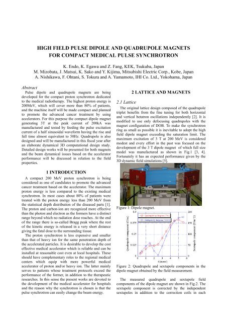
<strong>HIGH</strong> <strong>FIELD</strong> <strong>PULSE</strong> <strong>DIPOLE</strong> <strong>AND</strong> <strong>QUADRUPOLE</strong> <strong>MAGNETS</strong>FOR COMPACT MEDICAL <strong>PULSE</strong> SYNCHROTRONK. Endo, K. Egawa and Z. Fang, KEK, Tsukuba, JapanM. Mizobata, J. Matsui, K. Sako and Y. Kijima, Mitsubishi Electric Corp., Kobe, JapanA. Nishikawa, F. Ohtani, S. Tokura and A. Yamamoto, IHI Co. Ltd., Yokohama, JapanAbstractPulse dipole and quadrupole magnets are beingdeveloped for the compact proton synchrotron dedicatedto the medical radiotherapy. The highest proton energy is200MeV, which will cover more than 80% of patients,and the machine itself will be made compact and plannedto promote the advanced cancer treatment by usingaccelerators. For this purpose the compact dipole magnetgenerating 3T at the peak current of 200kA wasmanufactured and tested by feeding the pulse excitationcurrent of a half sinusoidal waveform having the rise andfall time almost equivalent to 50Hz. Quadrupole is alsodesigned and will be manufactured in this fiscal year afteran elaborate dynamical 3D computational design study.Detailed design works will be presented for both magnetsand the beam dynamical issues based on the acceleratorperformance will be discussed in relation to the fieldproperties.1 INTRODUCTIONA compact 200 MeV proton synchrotron is beingconsidered as one of candidates to promote the advancedcancer treatment based on the accelerator. The maximumproton energy is less compared to the existing medicalsynchrotron. In most cases about 80% of patients weretreated with the proton energy less than 200 MeV fromthe statistical depth distribution of the diseased parts [1].The proton and carbon-ion are recognized more effectivethan the photon and electron as the formers have a distinctrange beyond which no radiation dose reaches. At the endof the range there is so-called Bragg peak where the restof the kinetic energy is released in a very short distancegiving the fatal dose to the surrounding tissue.The proton synchrotron is less expensive and smallerthan that of heavy ion for the same penetration depth ofthe accelerated particles. It is desirable to develop the costeffective medical accelerator which is reliable and can beinstalled at reasonable cost even at local hospitals. Theseshould have complementary roles to the regional medicalcenters which equip with more powerful medicalaccelerator of proton and/or heavy ion. The latter mainlyserves to patients whose treatment protocols exceed theperformance of the former, in addition to the therapeuticresearches. In this sense the present works are devoted tothe development of the medical accelerator for hospitalsand the reason why the synchrotron is chosen is that thepulse synchrotron can easily change the beam energy.2 LATTICE <strong>AND</strong> <strong>MAGNETS</strong>2.1 LatticeThe original lattice design composed of the quadrupoletriplet benefits from the fine tuning for both horizontaland vertical betatron oscillations independently [2]. It ismodified to use only defocusing quadrupoles with themagnet configuration of DOB. To make the synchrotronring as small as possible it is inevitable to adopt the highfield dipole magnet exceeding the saturation limit. Themaximum excitation of 3 T at 200 MeV is consideredmodest and every effort in the past was focused on thedevelopment of the 3 T dipole magnet of which full sizemodel was manufactured as shown in Fig.1 [3, 4].Fortunately it has an expected performance given by the3D dynamic field simulations [5].Figure 1: Dipole magnet.Figure 2: Quadrupole and sextupole components in thedipole magnet obtained by the field measurement.The measured quadrupole and sextupole fieldcomponents of the dipole magnet are shown in Fig.2. Thesextupole component is corrected by the independentsextupoles in addition to the correction coils in each
dipole. The effect by the quadrupole component must becompensated by using the main quadrupole magnets.Considering the quadrupole field component in thebeam optics simulation as a thin lens approximation, itscontribution is a focusing element in the dipole magnet.To distribute the quadrupole component uniformly, thedipole is sliced into 21 elements between which 20 thinlens quadrupoles are inserted. The tune variation due tothe quadrupole error field is shown in Fig.3 and Fig.4compares the beam parameters both with and without thequadrupole error field.In Fig.5 the particle momentum varies from -1% to+1% by the RF acceleration and the quadrupole errorfield alters the twiss parameters.There exists a large sextupole error field in the dipole(Fig.2) which is not corrected merely by the independentsextupole magnets. By applying the correction windingsto the dipole it should be reduced less than 2.5 T/m 2 forwhich the particle tracking is given in Fig.6.Figure 6: Particle tracking at injection for (a) sextupoleerror field (SE=2.5 T/m 2 ) and QE=0, and (b) SE=2.5 T/m 2and QE=0.045 T/m. Sextupole error field is corrected inboth cases.Figure 3: Tune variations due to the quadrupole error field(-0.5 ~ 0.5 T/m) in the dipole magnet as a function of the15cm QD strength at 200 MeV.Figure 4: Beam parameters for (a) no quadrupole errorfield (QE=0 T/m) and (b) QE=0.39 T/m at 200MeV.For the positive quadrupole error field the dispersionfunction decreases, but the field error more than 0.75 T/mis not allowed in the lattice shown in Fig.4. As the presentdipole magnet gives small positive quadrupole component,the lattice parameters suffer small changes. The particlebehaviour observed at the long straight section in thepresence of only quadrupole field in the dipole is givenfor the injection field in Fig.5.2.2 Dipole MagnetA big modification in the dipole magnet design is toreplace the present coil made from the strand cable withthe hollow conductor made of OFC (Oxygen FreeCopper). The heat conductivity of the strand cable isinferior to the hollow conductor because of lacking themetallic contact between strands. To increase therepetition rate a good heat conduction is desirable.However, the eddy current in the hollow conductor has aneffect to the field distribution in the magnet gap.By the time-dependent 3D simulation which treats theeddy current, two cases with and without eddy current arecompared. Fig.7 shows both cases at 3 msec during theacceleration time of 5 msec. ‘No-eddy’ means the case ofstrand cable and ‘Eddy-01’ and ‘Eddy-02’ are for thehollow conductor. Difference of Eddy-02 from Eddy-01is only the conductor cut at the corner where the currentdensity is large but its effect is almost nothing.Figure 7: Field distributions of the dipole magnet at 3msec by the time-dependent 3D simulation. Cases ofEddy-01 and Eddy-02 differ only in the conductor crosssectionas shown in the right.Figure 5: Particle tracking at injection for (a) noquadrupole error field (QE=0) and (b) QE=0.045 T/m.It seems no essential difference in the field distributionbetween the strand cable and hollow conductor except
that the absolute flux density in the gap is higher to thehollow conductor than the strand cable. It is explainedthat the eddy current in the hollow conductor confines theflux inside the gap as shown in Fig.8 where the Bydistributions for 3 cases in Fig.7 are given by a color codeat the maximum field, 3T.Figure 8: Flux density (By) distributions for 3 casesshown in Fig.7 are given by the color code.2.3 Quadrupole MagnetAs shown in Fig.3 the operating point can be chosen toavoid the dangerous tunes by considering the effect of thegradient error in the dipole. The maximum field gradientis 30 T/m with the effective length of 15 cm (Fig.9). IfQF’s are required in the future, the present circumferenceof 9.5 m is resumed by the original 11.9 m toaccommodate them (8 QF’s) with applying modificationsto the bus-bar systems of dipole and quadrupole magnets.The computational gradient distributions for severalpole-shim arrangements and the effective gradient lengthare given in Fig.10 for the chamfered pole ends of 10 mmby 20 mm in length and height (Fig.11), respectively.Coil is made from the hollow conductor in 5 turns/poleand fits in the narrow spaces close to the horizontal andvertical axes allowing larger useful aperture as shown inFig.10(a).Figure 9: Quadrupole magnet.Figure 10: Computational gradient distributions (a) forseveral shim arrangements and the effective gradientlength (b) for the chamfered pole ends of 10 x 20 mm(length x height).Figure 11: Chamfered pole end.3 REFERENCES[1] Y. Hirao, “Results from HIMAC and Other TherapyFacilities in Japan,” Proc. Cyclotrons 2001, pp.8-12.[2] K. Endo et al, “Compact Proton and Carbon IonSynchrotrons for Radiation Therapy,” Proc.EPAC2002, Paris, pp.2733-5.[3] K. Endo et al, “Development of Compact ProtonSynchrotron for Radiation Therapy,” Proc.ARTA2003, Tokyo, pp.51-4.[4] K. Endo et al, “Development of High Field Dipole andHigh Current Pulse Power Supply for Compact ProtonSynchrotron,” Proc. PAC2003, Portland, pp.1071-3.[5] K. Endo et al, ”Development of High Field DipoleMagnet and Power Supply for Proton Therapy,” Proc.14 th SAST, Tsukuba, 2003, pp.196-8.