Recirculating Liquid Nitrogen System for Operation of Cryogenic ...
Recirculating Liquid Nitrogen System for Operation of Cryogenic ...
Recirculating Liquid Nitrogen System for Operation of Cryogenic ...

You also want an ePaper? Increase the reach of your titles
YUMPU automatically turns print PDFs into web optimized ePapers that Google loves.
plumbing connections to the storage tank; supply and return to VTF-2, and one input and exhaust line from eachcryogenerator. All <strong>of</strong> the lines which return nitrogen to the storage tank are mounted below the LN 2 level in thetank, which ensures thorough mixing with the stored LN 2 . The storage tank has a test pressure <strong>of</strong> 20 bar and isequipped with two safety release valves set to 14.5 bar.. A flow control valve is mounted in the LN 2 output line,downstream <strong>of</strong> the pump. The nitrogen return line is always open to the storage tank, but has a manual gate valvewhich can isolate the storage tank from the nitrogen supply and return lines. Cooling water is supplied at or below20 °C by a dedicated water chiller. The system is designed to be relatively easy to expand; additional SPC-4 unitscan be added later to cool the system more quickly or support more cryopumps.The cryogenerators are controlled by a Programmable Logic Controller (PLC) system which monitors thesystem pressure. As LN 2 at 94 K and 5 bar boils, it expands by roughly 35 times, which increases the pressure <strong>of</strong>the nitrogen storage tank. When the pressure reaches a set point, the PLC commands the cryogenerators to activate.Once the cryogenerators liquefy sufficient nitrogen to bring the pressure down to the desired level, thecryogenerators deactivate. The system is user-programmable and is typically set to turn the cryogenerators on at astorage tank pressure <strong>of</strong> 6 bar and turn them <strong>of</strong>f at 2 bar.When VTF-2 is inactive the cryogenerators run <strong>for</strong>approximately 35 minutes every 17 hours. During facility operation the cryogenerators operate nearly continuously.The automatic controls allow the system to operate without operator intervention nearly indefinitely.The cryogenerator has several integral sensors. Each cryogenerator senses water flow and temperature,helium working gas pressure, oil pressure, and several other parameters critical <strong>for</strong> operation. If one <strong>of</strong> theoperation-critical parameters is outside the tolerable range, the PLC will shut down the cryogenerator and sound analarm. Additionally, there are multiple sensors on the storage tank and nitrogen lines. Static and differentialpressure sensors are installed in the storage tank. The differential sensor measures pressure at the top and bottom <strong>of</strong>the LN 2 in the tank, which provides a liquid depth measurement. The nitrogen supply and return lines to the vacuumtank both have pressure and temperature sensors. There is a LN 2 rate flow sensor in the nitrogen supply line. Theoutputs from the pressure, temperature, and flow sensors are displayed on a touch screen control panel. The controlpanel also displays pump speed, control valve position, and cryogenerator RPM. The touch screen allows the user toselect “Pump” and “Idle” modes. In both modes, the cryogenerators turn on and <strong>of</strong>f at user-set storage tankpressures. In “Pump” mode the PLC also controls the pump and control valve, while in “Idle” mode the pump andcontrol valve are turned <strong>of</strong>f. The cryogenerator speeds are adjusted according to the system pressure; at highpressures the PLC commands the cryogenerators to turn at full speed (1,500 RPM), while at low pressure the PLCwill throttle the cryogenerators as low as 900 RPM.C. Data AcquisitionThe data in this work are collected via computer interfaces with the PLC, the pump thermocouples, and thevacuum gauge controller. The cryogenerator system state, the radiation shroud temperatures, and the facilitypressure are recorded by a computer. The cryogenerator state is monitored by RS-232 communication directly withthe PLC, which provides measurements <strong>of</strong> nitrogen supply temperature, pressure, and flow rate, nitrogen returnpressure and temperature, pump speed, control valve position, and pump head. The cryopump shrouds havemanufacturer-installed T-type thermocouples, and hence require no modification. The temperatures are monitoredby an Agilent multiplexer and sent to the computer via GPIB. The vacuum facility pressure is measured by a VarianXGC gauge controller, which simultaneously reads and reports the pressures measured by a Varian 571 and a VarianUHF-24 ion gauge. The ion gauge measurements are corrected <strong>for</strong> xenon during thruster testing. 5 The facilitypressure is sent to the computer by RS-232.III.<strong>Recirculating</strong> <strong>Liquid</strong> <strong>Nitrogen</strong> <strong>System</strong> DesignThe recirculating LN 2 system has four primary requirements: (1) deliver sufficient cooling to keep thecryopump shrouds at their optimal temperatures, (2) maintain a storage volume <strong>of</strong> LN 2 to allow immediate delivery<strong>of</strong> liquid on demand, (3) pump liquid to the vacuum facility, and (4) preferentially collect nitrogen gas from thesystem.4
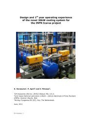
N 2 Return from VTF 27Pump2 16 5 4 3Cold HeadCryogenerator Inputand Return linesCold HeadLN 2 Supplyto VTF 2MotorMotorCryogenerator 2Cryogenerator 1Figure 4: Schematic <strong>of</strong> the SPC-8 RL Special system. Numbered items are hardware and sensor locations<strong>for</strong>: (1) return temperature, (2) return pressure, (3) supply temperature, (4) control valve, (5) supply flowrate, (6) supply pressure, and (7) storage tank pressure.A. Cooling CapacityThe first major requirement <strong>of</strong> a recirculating LN 2 system is delivered cooling capacity <strong>of</strong> the system. Theten cryopumps on VTF-2 require a combined LN 2 flow rate <strong>of</strong> 227 l/hr at steady state in order to cool the radiationshrouds sufficiently to keep the cryosails at their design temperature (13-15 K). The rate <strong>of</strong> 227 l/hr assumes thatthe cooling power is from boiling <strong>of</strong> the LN 2 alone; the pumps remain full <strong>of</strong> liquid. Thus, the cooling powerrequirement <strong>for</strong> the nitrogen shroud is purely from vaporization. A bulk storage tank <strong>of</strong> LN 2 with a supply pressure<strong>of</strong> 5 bar will provide saturated LN 2 at 94 K, which has a heat <strong>of</strong> vaporization <strong>of</strong> 4.855 kJ/mol and a density <strong>of</strong> 25.84mol/l. A flow <strong>of</strong> 227 l/h, then, will provide 7,911 W <strong>of</strong> cooling power. Any LN 2 recirculation system, then, musthave at least 7.9 kW <strong>of</strong> cooling power at 94 K and 5 bar.LN 2 cryogenerators with capacities <strong>of</strong> several kilowatts are commercially available. The Stirling<strong>Cryogenic</strong>s 6 SPC-4 cryogenerator is capable <strong>of</strong> approximately 5.4 kW <strong>of</strong> cooling at 94 K. The SPC-4 is a fourcylindercryogenerator which uses compressed helium gas to cool the nitrogen via the Stirling thermodynamic cycle,and requires only electrical power and cooling water. The SPC-4 only requires maintenance every 6,000 hours <strong>of</strong>operation.Figure 5 shows that the cooling power delivered by the SPC-4 cryogenerator varies inversely withtemperature. A system based on two SPC-4 cryogenerators will be able to provide 7.9 kW <strong>of</strong> cooling at 84 K;significantly lower than the desired delivery temperature. At 94 K, a two-SPC-4 system will deliver 10.7 kW <strong>of</strong>cooling; approximately 35% more than required by the cryopumps. The SPC-8 RL Special system integrated intoVTF-2 employs two SPC-4 cryogenerators.B. <strong>Liquid</strong> <strong>Nitrogen</strong> StorageThe second requirement <strong>of</strong> a recirculating LN 2 system is that it maintain a volume <strong>of</strong> liquid at all times sothat it can supply liquid to the cryopump shrouds on demand. The cryogenerators liquefy gas to produce liquid onlyas needed. The SPC-8 RL Special system at HPEPL has a 3,000 l, vacuum-jacketed LN 2 storage tank whichcontains approximately 1,500 liters <strong>of</strong> LN 2 .5
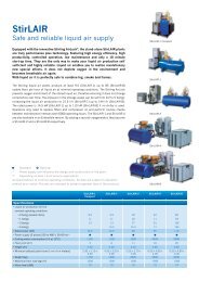
25Cooling Power (kW)201510One GeneratorTwo Generators580100Figure 5: Approximate cooling capacities <strong>for</strong> one and two SPC-4 cryogenerators as a function <strong>of</strong>temperature. 6C. <strong>Liquid</strong> <strong>Nitrogen</strong> DeliveryThe third requirement is a method to deliver nitrogen to the vacuum facility. Traditional bulk tank LN 2systems are pressure fed; the static pressure in the bulk tank <strong>for</strong>ces liquid through the cryopump shrouds. Bulk feedsystems use automatic gas vent valves to release evaporated gas, which maintains a constant reservoir <strong>of</strong> liquidinside the radiation shrouds. Since the evaporated nitrogen gas is vented as it is produced, a bulk tank system willonly supply liquid to replace the evaporated and vented gas. The cryogenerator system uses a pump to <strong>for</strong>ce liquidinto the cryopumps and back to the storage tank and liquefaction system. The pump can drive LN 2 at up to 1,200l/hr at a pressure head <strong>of</strong> 3 bar. An automatic control valve downstream <strong>of</strong> the pump maintains the pressure head at3 bar. The liquid flow rate is typically 1,100 l/hr during steady-state operation and slightly less, around 900 l/hr,during early pumpdown when rapid boiling increases flow resistance. Automatic gas vent valves cannot be used ina pump-fed system. Since the nitrogen that returns to the cryogenerators during steady-state operation is likely agas/liquid mixture, an automatic valve will unnecessarily throttle the LN 2 flow. Another method must be used toextract gas from the cryopumps while allowing liquid to enter.D. <strong>Nitrogen</strong> Gas Collection120140 160 180Temperature (K)The third requirement <strong>of</strong> a recirculating LN 2 system is the ability to return gas to the storage tank whileallowing liquid to remain in the radiation shrouds as long as possible. Figure 6 shows how this is accomplishedthrough a gravity feed system. LN 2 is first pumped above the vacuum tank, through a main line running down theaxis <strong>of</strong> the tank, and is able to pour into each cryopump shroud. The nitrogen leaving the LN 2 pump is compressedliquid; still at approximately the same temperature as the saturated liquid in the tank, but with the additional pressurefrom the pump head. This prevents gas bubble <strong>for</strong>mation in the LN 2 supply line. The shroud exhausts areconnected to a main return line which is approximately a meter higher than the supply line. This arrangement meansthat gas will preferentially collect in the return line, and is not present in the supply lines. In this way the shroudsonly receive liquid from the supply lines, and the evaporated gas is able to leave the shrouds without interfering withthe liquid supply. All <strong>of</strong> the nitrogen plumbing is vacuum insulated to eliminate unnecessary heat loss to theenvironment.2002202406
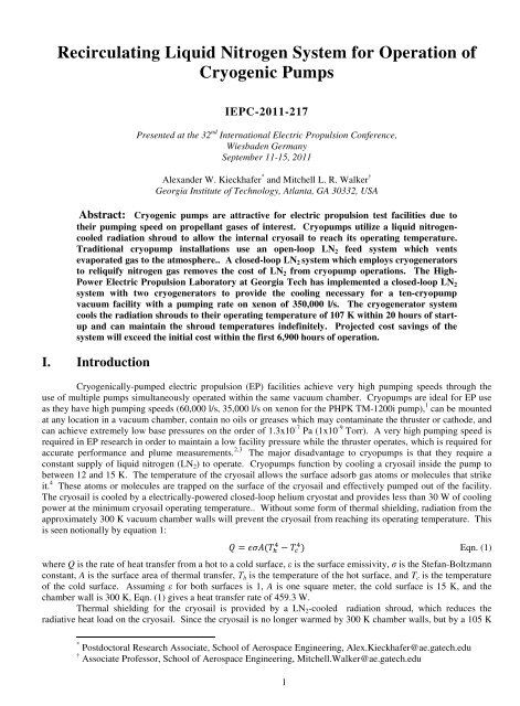
~1m height differenceGN 2 returnLN 2 SupplyCryopumpsVTF 2Figure 6: Notional side view <strong>of</strong> the nitrogen feed system to VTF-2. The cryogenerators, storage tank, and LN 2pump are to the left <strong>of</strong> the figure. The height difference ensures the return line fills with gas be<strong>for</strong>e thesupply line.IV.<strong>Recirculating</strong> <strong>Liquid</strong> <strong>Nitrogen</strong> Method <strong>of</strong> <strong>Operation</strong><strong>Operation</strong> <strong>of</strong> a recirculating system is very different from a pressure-fed bulk storage system. In traditionalbulk-tank-fed systems, activation <strong>of</strong> the nitrogen cooling is as simple as opening or closing a valve. A pump-fedcryogenerator system is necessarily much more complex to operate: the LN 2 pump, flow control valve, andcryogenerators are constantly monitored to ensure the system does not exceed its cooling capacity or pressure rating.The cryogenerator system has three primary phases <strong>of</strong> operation: (1) shroud warm-up and idle states, (2) steady-stateoperation <strong>of</strong> the radiation shrouds, and (3) initial cooldown <strong>of</strong> the radiation shrouds.A. Idle and Warm-Up ModesThe cryogenerator mode <strong>of</strong> operation is similar when idle and when the radiation shrouds are warming upafter a test. In both modes, the PLC turns <strong>of</strong>f the LN 2 pump and control valve, and the cryogenerators turn on onlywhen necessary to reduce the storage tank pressure. In idle mode the cryogenerators turn on approximately once per17 hours and run <strong>for</strong> 35-45 minutes. Figure 7 shows pressure in the nitrogen storage tank during an idle mode cycle.The abrupt change in slope <strong>of</strong> pressure with respect to time as the pressure drops below approximately 3.5 bar is dueto cryogenerator throttling; the cryogenerator speed is gradually reduced from 1,500 RPM to 900 RPM when thepressure iss below 4 bar. Using the predicted cooling rates <strong>of</strong> the cryogenerator system in the cooling cycle, thetotal energy removed from the system during cryogenerator operation is 22 MJ. This is equivalent to the energyreleased by evaporating 125 liters <strong>of</strong> LN 2 . Thus, the LN 2 system absorbs approximately 362 Watts from theenvironment, or an effective nitrogen boil rate <strong>of</strong> 7.4 l/hr.The facility is shut <strong>of</strong>f by turning <strong>of</strong>f the LN 2 pump and control valve. The cryogenerators continue to runas necessary to control the pressure. When first turned <strong>of</strong>f, the radiation shrouds are full <strong>of</strong> LN 2 , the boiling <strong>of</strong>which presents a significant additional thermal load on the cryogenerator system. Figure 8 shows the temperaturerise <strong>of</strong> the radiation shrouds after the nitrogen pumping is switched <strong>of</strong>f, as well as the storage tank pressure duringthe same period. The cryogenerators run twice in approximately 20 hours; a roughly 40% faster cycle time thanwhen the radiation shrouds are at room temperature, which indicates that approximately 175 liters <strong>of</strong> LN 2 evaporatesduring the warm-up process; 27 liters more than the 148 liters that evaporate in 20 hours while idle. The radiationshrouds reach 0 ºC within 10 hours <strong>of</strong> pump shutdown. Typically the facility should not be vented until the pumpsare above 0 ºC, and hence there is minimal risk <strong>of</strong> significant water condensation on cold pump surfaces. Thesystem requires approximately 20 hours to reach room temperature if left at vacuum.7
6Pressure (bar)543Cryogenerators OnCryogenerators Off05 10Time (hours)15Figure 7: Pressure <strong>of</strong> the nitrogen storage tank as a function <strong>of</strong> time during idle mode.300Temperature (K)250200LN 2 Pump OffPump 1 Pump 2Pump 3 Pump 4Pump 5 Pump 6Pump 7 Pump 8Pump 9 Pump 10<strong>Nitrogen</strong> Tank PressureCryogenerators On1086Pressure (bar)150Cryogenerators Off40Figure 8: Radiation shroud temperatures and nitrogen storage tank pressure as a function <strong>of</strong> time duringwarm-up when turned to idle mode.A. Radiation Shroud Cooldown510Time (hours)Cryopump radiation shroud cooldown presents the highest possible load to the closed-loop LN 2 system.LN 2 that enters the supply manifold, radiation shrouds, and return manifolds quickly boils and is returned to thestorage tank as warm gas. Figure 9 shows the pressure in the storage tank during the cooldown phase, which risesvery rapidly during LN 2 pump operation due to the high initial rate <strong>of</strong> gas production. When the system pressurereaches a user-set maximum pressure (6 bar in Figure 9), the cryogenerators activate. When the tank pressurereaches 10 bar, the PLC controller turns <strong>of</strong>f the LN 2 pump. This stops the flow <strong>of</strong> nitrogen to the facility to allowthe cryogenerators to bring the storage tank pressure back down by condensing gaseous nitrogen. When the tankreaches a user-set pressure (3.25 bar in Figure 9) the cryogenerators turn <strong>of</strong>f and the pump reactivates. Thecryogenerators have an additional safety mechanism which prevents them from turning on less than five minutes81520
after they are deactivated. Early in cooldown this delay means that the cryogenerators may not turn on until thesystem has already reached 10 bar and the pump has stopped. Later in the cooldown, the cryogenerators turn onwell be<strong>for</strong>e the LN 2 pump deactivates. Figure 9 shows that the cycle <strong>of</strong> rising and falling pressure is typicallyrepeated 18 times over 16 hours until gas returning from the radiation shrouds is approximately 110 K, which is coldenough that the cryogenerators can keep up with the cooling demand. The LN 2 pump stays on a little longer eachcycle as the radiation shrouds become progressively cooler and thus conduct less energy into the nitrogen. Once thecryogenerators can keep up with the cooling demand (after the 16.5-hour point in Figure 9) the storage tank pressurestabilizes and the LN 2 pump and cryogenerators remain active.10Storage Tank PressureLN 2 Pump SpeedPressure (Bar)8640Figure 9: LN 2 storage tank pressure and LN 2 pump speed during the cooldown phase <strong>of</strong> operation.B. Steady-State <strong>Operation</strong>510Time (hours)Steady-state operation is achieved when all ten radiation shrouds have reached their operating temperature.During steady-state operation the cooling load <strong>of</strong> the pumps is the equal to the cooling capacity <strong>of</strong> thecryogenerators; hence there is no net flow <strong>of</strong> energy into the storage tank and the tank pressure remains constant.For many tests, this means a tank pressure <strong>of</strong> between 4 and 5 bar, and hence a nitrogen temperature between 92 and95 K. The steady state temperature is determined by the cryogenerator cooling power capacity and the heat loads onthe radiation shrouds, and cannot be directly controlled without additional cryogenerator capacity or active reduction<strong>of</strong> the heat load on the shrouds.V. <strong>Recirculating</strong> <strong>Liquid</strong> <strong>Nitrogen</strong> <strong>System</strong> Per<strong>for</strong>manceA recirculating LN 2 system must cool as effectively as a traditional bulk tank feed system. There are twoprimary measures <strong>of</strong> per<strong>for</strong>mance which determine cooling effectiveness: (1) if radiation shrouds can reach theiroperating temperature, and (2) time required to cool the radiation shrouds to their operating temperature.Additionally, the rate <strong>of</strong> liquid consumption is critical to determine the net benefit <strong>of</strong> a recirculating system; sincethe recirculating system does not require nitrogen refill. The saved cost in LN 2 is used to determine the break-evenpoint <strong>of</strong> the system, which is the point after which the saved LN 2 refill costs are greater than the initial cost <strong>of</strong> thesystem.152052620LN 2 Pump RPM9
A. Radiation shroud Operating TemperatureTwo metrics can determine if the radiation shrouds reach their operating temperature: (1) whether thecryosails reach their operating temperature, and hence the facility reaches its operating pressure, and (2)measurements <strong>of</strong> the radiation shroud temperatures. The first metric is met since VTF-2 is able to achieve pressures<strong>of</strong> 2.5x10 -7 Pa (1.9x10 -9 Torr), which would be impossible if the radiation shrouds and cryosails could not reachtheir operating temperatures. The second metric is the temperature <strong>of</strong> the radiation shrouds: the colder the shroudsget, the better the cryopump will per<strong>for</strong>m as the helium-cooled sails can reach lower temperatures and hence pumpfaster. Figure 10 shows that, on average, the radiation shrouds maintain a temperature <strong>of</strong> approximately 106 K, witha maximum and minimum <strong>of</strong> 111 and 103 K, respectively. The shrouds show a roughly sinusoidal change intemperature which is almost perfectly in phase with the ambient temperature. The ambient temperature changes bymore than the radiation shroud temperatures, but this is likely due to the fact that the radiation shrouds are beingcooled by a LN 2 system which has a direct relationship between temperature and cooling power. Thus, thetemperature increase from a higher room temperature is damped by an increased cooling rate from thecryogenerators. The ambient temperature changes on a roughly 24-hour period, with the high points in the lateafternoon and the low points in the early morning, as would be expected in a non-climate-controlled space.The steady-state radiation shroud temperatures are significantly higher than the expected 84-94 K from thecryogenerator design. This difference is explained by the thermocouple locations and by examination <strong>of</strong> the LN 2supply and return temperatures from the cryogenerator system. The shroud thermocouples are measuringtemperature <strong>of</strong> the shroud itself, not the LN 2 lines on the shroud, so they will always read a higher temperature thanthe LN 2 flowing through the shrouds. Examination <strong>of</strong> the LN 2 temperatures in Figure 10 shows that the supply andreturn temperatures are 9-13 degrees lower than the radiation shroud temperatures. Furthermore, the supplytemperature remains steady at approximately 95 K. Additionally, the measured supply temperature is <strong>of</strong> the LN 2downstream <strong>of</strong> the pump, where it has been warmed from the conditions inside the storage tank by the energygained from the pump. The actual storage tank temperature is calculated from the tank pressure by assuming thetank is full <strong>of</strong> a saturated mixture <strong>of</strong> liquid and gas. This assumption is justified by the fact that the cryogeneratorexhausts and the LN 2 return are deep below the surface <strong>of</strong> the liquid; there is significant mixing in the tank, whichbrings it close to thermal equilibrium. The nitrogen tank pressure during the data collection in Figure 10 isapproximately 4.25 bar. A saturated liquid at this pressure is only 92 K; two degrees below the design target <strong>of</strong> 94K. At 92 K the cryogenerators provide 10.4 kW <strong>of</strong> cooling, equal to the evaporation <strong>of</strong> 291 l/hr <strong>of</strong> LN 2 . This powerindicates that the radiation shrouds experience a higher-than-expected thermal load from the environment, andjustifies the extra cooling capacity designed into the system.305300295110Temperature (K)105100LN 2 SupplyLN 2 ReturnPump 1 Pump 2 Pump 3Pump 4 Pump 5 Pump 6Pump 7 Pump 8 Pump 9Pump 10 Room Temperature9520 25 30 35 40 45 50 55Time (hours)Figure 10: LN 2 supply, LN 2 return, radiation shroud, and room temperatures during steady-state operation.10
The cryogenerator system must maintain the radiation shrouds at their operating temperature during activetesting when a thruster is exhausting hot gas into the facility. Figure 11 shows the average shroud temperature andvacuum facility pressure over the time range <strong>of</strong> interest. The testing shown in Figure 11 involved operating a Halleffect thruster at mass flow rates up to 9 mg/s. The facility pressure is never greater than 6x10 -4 Pa (4.5x10 -6 Torr-Xe). The average radiation shroud temperature shows no significant change due to the mass flow into the system,and instead only follows the roughly-sinusoidal behavior seen in the ambient temperature. The fact that theradiation shrouds appear immune to the thruster is due in part to shielding inside the facility; graphite shielding hasbeen placed between the radiation shrouds and the thruster. Thus, very little <strong>of</strong> the thruster jet power is transmittedto the pumps.108Average Pump TemperatureNude Ion Gauge PressureTube Ion Gauge Pressure10 -310 -4Temperature (K)106104Changes in mass flow(max 9 mg/s <strong>of</strong> xenon)Changes in mass flow(max 9 mg/s <strong>of</strong> xenon)10 -510 -610 -7Pressure (Torr <strong>of</strong> xenon)10210 -81000Figure 11: Average radiation shroud temperature and facility pressure as a function <strong>of</strong> time during steadystateoperation with a HET operating at up to 300 V, 9 A, 9 mg/s xenon.The LN 2 system meets the first criterion: it is able to cool the radiation shrouds to the point where they areeffective. The radiation shroud shrouds show small changes over the course <strong>of</strong> a day <strong>of</strong> testing, but these changesare explained by the heat load on the system from the ambient air outside the facility. Furthermore, the cryopumpshroud temperatures do not change as a function <strong>of</strong> thruster mass flow or power input. The cryogenerator systemholds the radiation shrouds at their operating temperature as long as desired, without any need <strong>for</strong> LN 2 resupply.B. Initial Cooling Rate51015 20Time (hours)The time required to bring the radiation shrouds to their operating temperature is <strong>of</strong> major concern in afacility which experiences short and frequent testing cycles. Figure 12 shows that the radiation shroud temperaturesdecrease due to the LN 2 flow from the system, then increase when the LN 2 pump shuts <strong>of</strong>f to allow thecryogenerators to lower the system pressure. The first on-<strong>of</strong>f cycle <strong>of</strong> the LN 2 pump cools the pumps very littlebecause nitrogen at this early stage cools the supply lines. Subsequent cycles have much larger effects on theradiation shroud temperatures.The radiation shrouds experience very different cooling rates, cooling down in pairs according to theirposition on the facility as shown in Figure 13. This is a result <strong>of</strong> the gravity feed system which does not activelyregulate the nitrogen flow rate, but rather allows liquid to be pulled by gravity. Pumps 1 and 6, <strong>for</strong> example, are thelowest pumps in the system and as such cool down the quickest. Pumps 7 and 10 are the next lowest, followed by 2and 5, 8 and 9, and finally 3 and 4. Since pumps 3 and 4 are highest in the system, they are the last to receive asignificant quantity <strong>of</strong> LN 2 and hence stay within ten degrees <strong>of</strong> 0 °C (273 K) until approximately 12 hours aftercryogenerator system start-up. The on-<strong>of</strong>f cycles on the LN 2 pump continue <strong>for</strong> approximately 16 hours, after which1125303510 -9
the LN 2 return temperature is low enough that the cryogenerators can control the storage tank pressure while theLN 2 pump is active. The shrouds reach their operating temperatures approximately 19 hours after starting thecryogenerator system. The different cooling rates on each radiation shroud are not important to the total timerequired to cool the system. Since the system has a fixed thermal capacity, the only important result is that all tenshrouds reach the same final temperature at the same time. The coldest radiation shrouds present the smallest loadto the cryogenerator system, so as some shrouds cool down they put less energy into the nitrogen, which allows theLN 2 pump to run longer and hence cool the remaining shrouds. This is most evident in the temperatures <strong>of</strong> pumps 3and 4 at the end <strong>of</strong> the cooldown cycle; once pumps 1, 2, and 5-10 have nearly reached their operating temperature,pumps 3 and 4 finally see significant cooling and their temperature drops by almost 150 K in the last three cycles.Temperature (K)300250200Pump 1Pump 2Pump 3Pump 4Pump 5Pump 6Pump 7Pump 8Pump 9Pump 10RPM150051015Time (hours)2052620Pump speed (RPM)Figure 12: Radiation shroud temperatures and nitrogen pump RPM during initial cooldown.The equivalent amount <strong>of</strong> LN 2 necessary to cool the shrouds from room temperature to operatingtemperature is calculated by assuming the nitrogen in the storage tank contains a saturated liquid. The tank pressureis used to calculate the liquid temperature, from which the cooling rate <strong>of</strong> the cryogenerators is calculated. Figure12 shows that the storage tank is between 3.25 bar and 11 bar during cooldown, which translates to cryogeneratorcooling rates between 9.5 and 12.5 kW. A piecewise integration <strong>of</strong> the cryogenerator cooling rates, combined withthe heat <strong>of</strong> vaporization and density <strong>of</strong> LN 2 , gives an estimate <strong>of</strong> the amount <strong>of</strong> nitrogen required to cool theradiation shrouds down to their operating points. The time-averaged cooling rate <strong>of</strong> the cryogenerators is 9.3 kW,including times when the system pressure is low and the cryogenerators are deactivated. Average cooling powerwhile the cryogenerators are active is 11.3 kW, which translates to an 82% duty cycle. This agrees with the data inFigure 12 which shows the times <strong>of</strong> decreasing pressure (cryogenerators on) is much larger than the time withcryogenerators <strong>of</strong>f. The total cooling energy expended to bring the radiation shrouds to their operating temperatureis approximately 586 MJ, or the evaporation <strong>of</strong> 4970 liters <strong>of</strong> LN 2 . It requires an effective evaporation rate <strong>of</strong> 290l/hr to keep the system at steady state, the system will be able to operate <strong>for</strong> 2.4 days on the volume <strong>of</strong> nitrogennecessary to cool the system. The calculated nitrogen usage quantifies the vast difference between nitrogen usageduring cooldown and nitrogen usage during steady-state operation.12
7Door 10Figure 13: Notional schematic <strong>of</strong> pump locations at the downstream (left) and door (right) ends <strong>of</strong> VTF-2.Figure 14 shows the effect <strong>of</strong> the reduced load on the nitrogen system due to reduced radiation shroudtemperatures, as seen by the nitrogen supply and return temperatures. The nitrogen supply temperature is highest atthe very beginning <strong>of</strong> pumping, at which point the temperature probe and surrounding piping are still being cooled.<strong>Nitrogen</strong> supply temperatures in the subsequent cycles increase slightly until the 8 th cycle, after which they arerelatively constant. The return temperature is a major driver in power deposition into the storage tank. <strong>Nitrogen</strong>returning to the storage tank early in the cooldown process is 150-200 °C warmer than the nitrogen in the supplyline, due to the nitrogen lines warming the gas to near room temperature. Since the return lines are almostcompletely full <strong>of</strong> gas <strong>for</strong> much <strong>of</strong> the cool down process, their temperature rises significantly while the nitrogenflow is <strong>of</strong>f as there is no potential to boil <strong>of</strong>f liquid as a thermal buffer. The cycles in supply and return temperaturesare almost exactly in phase with the LN 2 flow rate; every time flow starts the supply and return temperatures quicklydrop, and every time the flow stops the temperatures begin to rise. Early in cool down the high temperature <strong>of</strong>returning gas is as much or more <strong>of</strong> a heat load than liquid boiling; It takes approximately 34 kW to boil 1,100 litersper hour <strong>of</strong> LN 2 . Heat loads early in cooldown, however, are closer to 80-90 kW as determined by control-volumetheory; the energy removed by the cryogenerators during cycle 1 is by definition equal to the energy added by thereturning nitrogen during the same time. Since the cryogenerator system is only removing heat at a rate <strong>of</strong>approximately 11 kW, the cryogenerators will need to run <strong>for</strong> 8.2 minutes <strong>for</strong> every minute <strong>of</strong> LN 2 pump operationearly in the cooldown cycle, when the LN 2 flow rate is throttled to between 900 and 1,000 l/hr.The recirculating nitrogen system brings the radiation shrouds to their operating temperature <strong>of</strong>approximately 105 K within 20 hours <strong>of</strong> startup. Figure 15, however, shows that the vacuum facility reaches highvacuum well be<strong>for</strong>e the shrouds have reached steady state, indicating that some <strong>of</strong> the cryosails are at their operatingtemperature as soon as 10 hours after system startup. The facility pressure reaches 13 mPa (10 -4 Torr) from thenitrogen system alone, and is below 1.3x10 -5 Pa (1x10 -7 Torr) 10 hours after startup. At this point the shrouds andcryosails on pumps 1, 6, 7, and 10 are at or near their operating temperatures, and shrouds and cryosails on pumps 2and 5 are rapidly approaching steady state. Pumps 3, 4, 8, and 9 are still too warm to be effectively pumping, but sixpumps is sufficient to bring the facility pressure below 1.3x10 -5 Pa (1x10 -7 Torr). Tasks such as cathode purging andmass flow calibration can be per<strong>for</strong>med at this time; the increase in pressure at the 11-hour mark in Figure 15 is dueto a cathode purge, and the spikes at 15 and 16 hours are from mass flow calibrations. The cryopump heliumcompressors and ionization gauges are usually switched on after the third cryogenerator cycle during cool down. Atthat point, all <strong>of</strong> the radiation shrouds except those on pumps 3 and 4 are below 0 °C, and are effectively freezingwater out <strong>of</strong> the facility. The cryosails reach their operating temperature soon after the radiation shrouds reach ~110K. In the case <strong>of</strong> pumps 3 and 4, the sails cool to approximately 160 K during the last few cycles <strong>of</strong> thecryogenerators.13
<strong>Nitrogen</strong> flow (liters/hour)10005000<strong>Liquid</strong> <strong>Nitrogen</strong> Flow Rate<strong>Nitrogen</strong> Supply Temperature<strong>Nitrogen</strong> Return Temperature300250200150Temperature (K)100Figure 14:cooldown.05101520Time (hours)<strong>Nitrogen</strong> supply and return temperatures and LN 2 flow rate as a function <strong>of</strong> time duringTemperature (K)30025020015010 -3Cryosails ActivatedCathode PurgingPump 1 TemperaturePump 3 TemperatureNude Ion GaugeTube Ion GaugeMass Flow Calibrations10 -410 -510 -6Pressure (Torr)10 -70510Time (hours)Figure 15: Shroud temperature <strong>of</strong> pumps 1 and 3, and VTF-2 vacuum pressure as a function <strong>of</strong> time duringcooldown.152010 -814
VI.Comparison with Bulk StorageEnergy analysis <strong>of</strong> the LN 2 system has provided the amount <strong>of</strong> LN 2 that must be evaporated to cool thesystem (4970 liters), maintain a cold system (290 l/hr), and maintain LN 2 in the storage tank while the system is idle(7.4 l/hr). An effective cost <strong>of</strong> operation is calculated from these LN 2 usage rates and an approximate bulk price <strong>of</strong>$0.35/l <strong>of</strong> LN 2 . There<strong>for</strong>e a bulk feed system on VTF-2 will require nitrogen costing approximately $1,700 to cooldown the system, $100/hour to operate at steady state, and $2.60/hour to sit idle. A short test with 6 hours <strong>of</strong> testtime will cost $2,400. A two-week-long wear test will cost $35,000, and a 5,000-hour life test will cost $502,000.The SPC-8 RL Special system cost $700,000 in 2010. Figure 16 shows a cost comparison between lifetesting, repeated pumpdowns with 10 hours at high vacuum, and the cryogenerator system. At $0.35 per liter it willrequire 6,900 hours <strong>of</strong> steady-state operation <strong>for</strong> the saved cost <strong>of</strong> LN 2 to equal the initial cost <strong>of</strong> the cryogeneratorsystem. This is not a very long time; lifetime tests <strong>of</strong> EP thrusters commonly exceed 8,000 hours. Additionally,much <strong>of</strong> the testing in VTF-2 consists <strong>of</strong> short tests, typically 10 hours <strong>of</strong> thruster operation, so a single test will costapproximately $2,800, thus requiring 250 pumpdown cycles to pay <strong>for</strong> the system. A thruster test cycle with 10hours <strong>of</strong> test time will require approximately 50 hours total to cool the pumps down, run the test, and warm thepumps back up, so 250 tests will use LN 2 equal to 6,900 hours <strong>of</strong> steady-state operation.Figure 16: Costs <strong>of</strong> continuous 10-hour tests, continuous steady-state use, and the cryogenerator systemduring VTF-2 operation as a function <strong>of</strong> time.VII. Conclusions1.4x10 6Cost ($)1.21.00.80.60.40.20.00310-hour testsContinuous TestingCryogenerator Cost6 9Time (hours)15x10 3The addition <strong>of</strong> the Stirling SPC-8 cryogenerator system to VTF-2 at HPEPL proves that there is a closedloopLN 2 alternative to costly and inconvenient bulk storage tanks. The SPC-8 system is able to bring the radiationshrouds on all ten TM-1200i cryopumps in VTF-2 to their operating temperature <strong>of</strong> 105 K in approximately 20hours at a LN 2 storage tank pressure <strong>of</strong> 4.25 bar, can autonomously maintain the pump temperatures nearlyindefinitely, and can do so without venting any nitrogen. Thermodynamic and system data indicate that VTF-2requires the equivalent energy <strong>of</strong> boiling 4,970 liters <strong>of</strong> LN 2 to cool down to its operating temperature, 290 l/hr <strong>for</strong>steady-state operation, and 7.4 l/hr to sit idle. The cryogenerator system is fully automated and can be left active <strong>for</strong>long periods <strong>of</strong> time with no operator interaction.The advantages <strong>of</strong> a closed-loop LN 2 system justify the extra expense <strong>of</strong> installation and the long cooldown times.The SPC-8 RL Special system on VTF-2 pays <strong>for</strong> itself after a single 6,900-hour wear test or after 250 short (10hour) tests, based on an estimated $0.35/l bulk LN2 price. A closed-loop system with a nominal storage tank alwayshas LN 2 available <strong>for</strong> delivery. The cryogenerators act reactively, to re-liquefy evaporated nitrogen, rather than on aconstant basis, meaning that no energy is wasted cooling nitrogen that is already a liquid. The cryogenerator systemremoves the cost and logistical issues associated with LN 2 supply to a cryopump radiation shroud, and replaces themwith a nearly unlimited LN 2 supply available at the push <strong>of</strong> a button.1215
AcknowledgementsThe authors would like to acknowledge the <strong>of</strong> Hoang Dao <strong>for</strong> fabricating and programming the dataacquisition system, Johan du Pisanie and Jorrit Coolen at Stirling Cryogenenics <strong>for</strong> their assistance withprogramming the PLC interface, the rest <strong>of</strong> the students at HPEPL <strong>for</strong> their assistance running the vacuum facility,and the staff at Stirling <strong>Cryogenic</strong>s <strong>for</strong> helping us with installation and operation <strong>of</strong> the cryogenerator system.1 PHPK TM-1200i Product Datasheet2 Walker, M.L.R., Effects <strong>of</strong> Facility Backpressure on the Per<strong>for</strong>mance and Plume <strong>of</strong> a Hall thruster, Ph.DDissertation, University <strong>of</strong> Michigan, 20053 Randolph, T., et. al., “Facility Effects on Stationary Plasma Thruster Testing, 23 rd International ElectricPropulsion Conference, Seattle, WA, Sept 13-16, 1993, IEPC-93-0934 Cai, C., Boyd, I., and Sun, Q., “Free Molecular Flows Between Two Plates Equipped with Pumps,”Journal <strong>of</strong> Thermophysics and Heat Transfer Vol. 21, No. 1, pp. 95-1045Vacuum Measurement, Varian, Inc., 2005, Available from:http://www.varianinc.com/cgi7bin/nav?products/vacuum/measure/index&cid=IPMHIKJQFO.6 http://www.stirlingcryogenics.com16