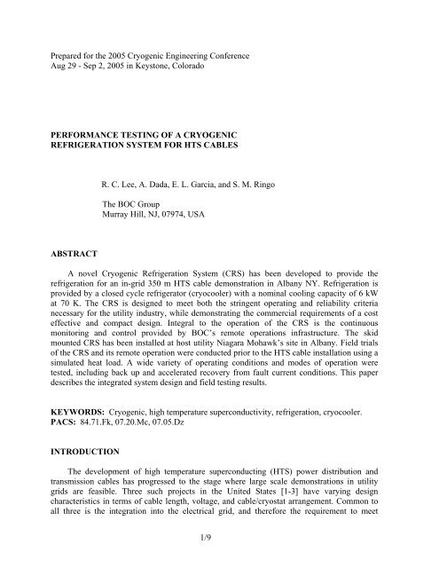
Performance testing of a cryogenic refrigeration system for HTS cables
Performance testing of a cryogenic refrigeration system for HTS cables
Performance testing of a cryogenic refrigeration system for HTS cables

You also want an ePaper? Increase the reach of your titles
YUMPU automatically turns print PDFs into web optimized ePapers that Google loves.
thermosyphon is in a state <strong>of</strong> quasi-equilibrium. There is a balance between the evaporationoccurring at the cable heat exchange surfaces, and the condensation that occurs in thecryocooler. Nitrogen mass is neither gained nor lost in the thermosyphon. The purpose <strong>of</strong> theliquid nitrogen tank during normal operation is to maintain stable cooling loop operatingpressure, as well as providing a buffer <strong>for</strong> liquid expansion and contraction. Some <strong>HTS</strong> cablecooling <strong>system</strong>s have used an alternative arrangement <strong>for</strong> pressure control employingpressurizing helium gas. The advantage <strong>of</strong> helium is that it can be maintained as a gas at thecable operating temperature and pressure. However, there is recent evidence that shows thispressurizing arrangement runs the risk <strong>of</strong> <strong>for</strong>ming a helium bubble downstream in the <strong>HTS</strong>cable cryostat through a combination <strong>of</strong> absorption and desorption driven by smalltemperature and pressure differences over an extended period <strong>of</strong> time [10].In the event <strong>of</strong> cryocooler failure or maintenance, the thermosyphon switches from aclosed to open mode operation. Nitrogen evaporated from the heat exchange surfaces isremoved from the thermosyphon with the aid <strong>of</strong> a vacuum pump to maintain low operatingpressures required <strong>for</strong> this subcooler mode <strong>of</strong> operation. The level <strong>of</strong> liquid nitrogen ismaintained by withdrawing liquid nitrogen from the subcooled loop. The purpose <strong>of</strong> the liquidnitrogen tank is now two-fold, by passively maintaining both the subcooled loop temperatureand liquid inventory. Relatively warm liquid nitrogen from the bulk liquid nitrogen tank iscooled to cable operating temperature by first passing through the thermosyphon.CRS Mechanical DesignThe core elements <strong>of</strong> the CRS are housed in a vacuum insulated cold box that measuresapproximately 1.4 m high by 1.6 m long. The principal elements housed in the cold box arethe thermosyphon, two BNCP-53 Barber-Nichols liquid nitrogen pumps, and associated valvesand piping. FIGURE 3 shows a cutaway <strong>of</strong> the cold box, and the overall skid arrangement <strong>for</strong>the cold box and cryocooler. The cryocooler selected <strong>for</strong> the CRS is a Stirling cycle LPC-8manufactured by Stirling Cryogenics & Refrigeration BV. The LPC-8 consists essentially <strong>of</strong>two identical LPC-4 units, with a common control <strong>system</strong>. The LPC-4 has a nominal coolingcapacity <strong>of</strong> 4 kW at 77 K, which means the LPC-8 is the smallest standard unit that met thespecification <strong>of</strong> 5 kW at 77 K <strong>for</strong> the Albany project. The individual cryocoolers are connectedto the cold box through a ‘plug and play’ arrangement using flexible vacuum jacketed lines.The lines are arranged to allow the cold heads to be removed without isolating them from the1.4 mFIGURE 3. Scaled mechanical drawing <strong>of</strong> cold box and skid arrangement1.6 m5/9
a) b)FIGURE 4. Internal view <strong>of</strong> cold box (a) and skid mounting arrangement (b).thermosyphon. All serviceable components are then accessible <strong>for</strong> maintenance. FIGURE 4shows pictures <strong>of</strong> the cold box and skid that were fabricated by CVIP, Inc.The backup cooling arrangement uses a GV-400 Drystar vacuum pump manufactured byBOC Edwards. The vacuum pump operates warm, with the cold vent nitrogen heated using anelectric heater. Calculations indicated the GV-400 would have an equivalent cooling capacity<strong>of</strong> more than 5 kW at 70 K.CRS ControlThe Albany CRS has two levels <strong>of</strong> overall control. Direct control <strong>of</strong> all equipment isprovided by a Siemens Simatic TI545 PLC at the Albany site. This PLC then communicates tothe secure BOC intranet using a Wonderware 9.0 interface. The Wonderware interface isavailable both onsite in Albany and remotely at the BOC ROC as shown in FIGURE 5. TheROC is an existing BOC resource which provides 24/7 operation <strong>for</strong> BOC plants throughoutthe United States. The protocol adopted <strong>for</strong> the Albany <strong>HTS</strong> project is that the ROC will havesole responsibility <strong>for</strong> the operation <strong>of</strong> the CRS, as well as provide the interface between thea) b)FIGURE 5. Local Albany (a) and Remote Operation Center (b) control interfaces.6/9
TABLE 2. Overall test resultsItemMaximum cryocooler capacity at 70 KMaximum backup (vacuum) capacity at 70 KTemperature stability during normal cryocooler operationTemperature stability during backup (vacuum) operationMinimum operating temperatureResult> 6.0 kW> 5.5 kW< 0.1 K< 0.7 K< 67 K<strong>HTS</strong> cable project and the Niagara Mohawk Eastern Regional Control Center. All dataassociated with the <strong>HTS</strong> cable, from the CRS and otherwise, will be processed and stored on aBOC server. That data will then be available globally on a secure, read-only basis to theproject partners.Test ResultsInstallation <strong>of</strong> the CRS was completed by the end <strong>of</strong> June 2005, with commissioning andper<strong>for</strong>mance <strong>testing</strong> per<strong>for</strong>med over the following six weeks. The most important per<strong>for</strong>manceparameters are the cooling capacity and temperature stability at design conditions. Most testswere conducted with a CRS outlet (cable inlet) temperature <strong>of</strong> 70 K, although stable operationhas been achieved at temperatures below 67 K. Coolant flow rate during the tests wasnominally 40 liters/min. In all cases, the project requirements have been met or exceeded.TABLE 2 summarizes key per<strong>for</strong>mance test results. Maximum cooling capacity is over 6 kWand 5.5 kW <strong>for</strong> the cryocooler and backup vacuum <strong>system</strong>, respectively, at 70 K. The controlstability and thermosyphon heat exchanger efficiency remained excellent at all operatingtemperatures from 77 K to below 67 K. The maximum thermosyphon heat exchanger capacityhas not been verified because <strong>of</strong> the 8 kW heating limit. Stable operation was achieved with acombination <strong>of</strong> cryocooler and vacuum pump producing 8 kW cooling at 67 K. Thiscombination <strong>of</strong> cryocooler and vacuum pump operation is potentially important as a means torecover quickly to acceptable temperature levels following a fault current event. The combinedcooling capacity is expected to be nearly 11 kW at 70 K.Overall control stability was <strong>testing</strong> using a worst case step response scenario. Followingestablishment <strong>of</strong> stable operating conditions at 3.5 kW cooling and 70 K coolant temperature,78763.5 to 5.1 kW step (+-5%)78763.5 to 5.2 kW step (+-5%)747472Cable outlet72Cable outlet7068Cable inlet: 70K, +0.09, -0.097068Cable inlet: 70K, +0.68, -0.46660 500 1000 1500 2000 2500660 2000 4000 6000 8000Time (sec)Time (sec)a) b)FIGURE 6. CRS step control response during cryocooler (a) and vacuum pump (b) operation.7/9
7876743.5 kW to 6.3 kW ramp787674Cryocooler 'failure'72Cable outlet72Cable outlet7068Cable inlet: 70K, +0.10, -0.087068Cable inlet: 70K, +0.59, -0.16660 500 1000 1500 2000 2500 3000Time (sec)FIGURE 7. Ramp response <strong>of</strong> CRS with cryocooler.660 1000 2000 3000 4000Time (sec)FIGURE 8. CRS response to cryocooler failure.the heater power was step increased by approximately 1.6 kW. As soon as stable conditionswere again achieved, the heater power was reduced to its original 3.5 kW value. The resultsare shown in FIGURE 6 <strong>for</strong> both cryocooler and vacuum pump operation. In both cases, thetemperature stability requirements <strong>for</strong> normal/cryocooler (±0.1 K) and backup/vacuum pump(±0.1 K) were met. The increased ‘noise’ evident during backup operation is due to the action<strong>of</strong> the thermosyphon liquid nitrogen fill valve and associated small temperature and flowvariations.FIGURE 7 shows the result <strong>of</strong> a relatively gradual increase in cryocooler cooling capacityfrom 3.5 kW to 6.3 kW at 70 K. The temperature stability during this test remained withinspecifications, and the final operating point represents nearly the maximum cryocooler coolingcapacity (6.3 kW at 70 K). FIGURE 8 shows the response <strong>of</strong> the <strong>system</strong>, in fully automaticmode, when the cryocooler abruptly ‘fails’. The small temperature rise (0.59 K) following thesimulated failure is due to the control logic needing to determine that there has been a coolingfailure, and automatically switching to the backup vacuum pump operation. The temperaturerise seen during this switchover is much larger than would occur in practice because thewarming CRS outlet coolant would not immediately feed back into the CRS as warming returncoolant.SUMMARYThe <strong>cryogenic</strong> <strong>refrigeration</strong> <strong>system</strong> <strong>for</strong> the Albany <strong>HTS</strong> cable has been installed andcommissioned using a temporary heated piping section representing the cable. The overallper<strong>for</strong>mance <strong>of</strong> the <strong>system</strong> has in all cases met or exceeded project requirements. All controlshave been implemented and the <strong>system</strong> is operational in fully automatic and remote operation.During the remainder <strong>of</strong> 2005, the final interface with the <strong>HTS</strong> cable and the Niagara MohawkEastern Regional Control Center will be completed. Installation <strong>of</strong> the <strong>HTS</strong> cable andterminations is expected by the end <strong>of</strong> 2005, and the first cable cooldown is scheduled <strong>for</strong>early 2006.8/9
ACKNOWLEDGEMENTSThis work was supported in part by the U.S. Department <strong>of</strong> Energy under Contract #DE-FC36-03GO13031 and by New York State Energy Research and Development Authorityunder Agreement #6481.REFERENCES1. Weber, C. S., et al., “Overview <strong>of</strong> the Underground 34.5 kV <strong>HTS</strong> Power Cable Program in Albany, NY,”IEEE Transactions on Applied Superconductivity 15, No. 2, pp. 1793-1797 (2005).2. Gouge, M. J., et al., “Tests <strong>of</strong> Tri-Axial <strong>HTS</strong> Cables,” IEEE Transactions on Applied Superconductivity 15,No. 2, pp. 1827-1830 (2005).3. Maguire, J. F., et al., “Development and Demonstration <strong>of</strong> a Long Length <strong>HTS</strong> Cable to Operate in the LongIsland Power Authority Transmission Grid,” IEEE Transactions on Applied Superconductivity 15, No. 2, pp.1787-1792 (2005).4. Demko, J. A., et al., “Acceptance Test and Operation <strong>of</strong> the Southwire Company 30-m High-TemperatureSuperconducting Cable Cryogenic System,” in Advances in Cryogenic Engineering 47a, edited by S. Breonet al., American Institute <strong>of</strong> Physics, New York, 2000, pp. 180-187.5. Koh, D., et al., “<strong>Per<strong>for</strong>mance</strong> Tests <strong>of</strong> High Temperature Superconducting Power Cable Cooling System,”IEEE Transactions on Applied Superconductivity 14, No. 2, pp. 1746-1749 (2004). Korea, open cycle 10m6. Tønnesen, O., et al., “Operation experiences with a 30 kV / 100 MVA high temperature superconductingcable <strong>system</strong>,” Supercond. Sci. Technol. 17, pp. S101-S105 (2004).7. Lee, R. C., Dada, A. and Ringo, S. M., “Cryogenic Refrigeration System <strong>for</strong> <strong>HTS</strong> Cables,” IEEETransactions on Applied Superconductivity 15, No. 2, pp. 1798-1801 (2005).8. Masuda, T., et al., “Design and Experimental Results <strong>for</strong> Albany <strong>HTS</strong> Cable,” IEEE Transactions on AppliedSuperconductivity 15, No. 2, pp. 1806-1809 (2005).9. Masuda, T., et al., “Development <strong>of</strong> a 100 m, 3-core 114 MVA <strong>HTS</strong>C cable <strong>system</strong>,” Physica C, pp. 1580-1584 (2004).10. Ichikawa, M., et al., “Thermomechanical Characteristics <strong>of</strong> 500-m <strong>HTS</strong> Power Cable,” IEEE Transactionson Applied Superconductivity 15, No. 2, pp. 1771-1774 (2005).9/9