Stirling Power Cooler LPC-RL - Stirling Cryogenics
Stirling Power Cooler LPC-RL - Stirling Cryogenics
Stirling Power Cooler LPC-RL - Stirling Cryogenics

You also want an ePaper? Increase the reach of your titles
YUMPU automatically turns print PDFs into web optimized ePapers that Google loves.
SC.1.1.1003<br />
<strong>Stirling</strong> <strong>Power</strong> <strong>Cooler</strong> <strong>LPC</strong>-<strong>RL</strong><br />
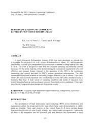
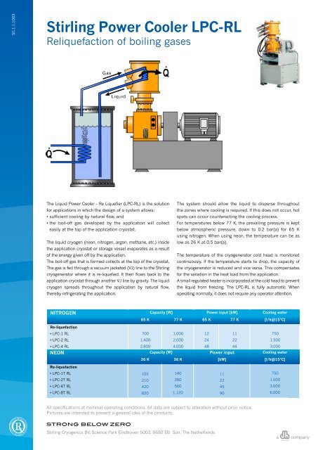
Reliquefaction of boiling gases<br />
The Liquid <strong>Power</strong> <strong>Cooler</strong> - Re Liquefier (<strong>LPC</strong>-<strong>RL</strong>) is the solution<br />
for applications in which the design of a system allows:<br />
• sufficient cooling by natural flow, and<br />
• the boil-off gas developed by the application will collect<br />
easily at the top of the application cryostat.<br />
The liquid cryogen (neon, nitrogen, argon, methane, etc.) inside<br />
the application cryostat or storage vessel evaporates as a result<br />
of the energy given off by the application.<br />
The boil-off gas that is formed collects at the top of the cryostat.<br />
The gas is fed through a vacuum jacketed (VJ) line to the <strong>Stirling</strong><br />
cryogenerator where it is re-liquefied. It then flows back to the<br />
application cryostat through another VJ line by gravity. The liquid<br />
cryogen spreads throughout the application by natural flow,<br />
thereby refrigerating the application.<br />
The system should allow the liquid to disperse throughout<br />
the zones where cooling is required. If this does not occur, hot<br />
spots can occur counteracting the cooling process.<br />
For temperatures below 77 K, the prevailing pressure is kept<br />
below atmospheric pressure, down to 0.2 bar(a) for 65 K<br />
using nitrogen. When using neon, the temperature can be as<br />
low as 26 K at 0.5 bar(a).<br />
The temperature of the cryogenerator cold head is monitored<br />
continuously. If the temperature starts to drop, the capacity of<br />
the cryogenerator is reduced and vice versa. This compensates<br />
for the variation in the heat load from the application.<br />
A small regulated heater is incorporated at the cold head to prevent<br />
the liquid from freezing. The <strong>LPC</strong>-<strong>RL</strong> is fully automatic. When<br />
operating normally, it does not require any operator attention.<br />
NITROGEN Capacity [W] <strong>Power</strong> input [kW] Cooling water<br />
65 K 77 K 65 K 77 K [l/h@15°C]<br />
Re-liquefaction<br />
• <strong>LPC</strong>-1 <strong>RL</strong><br />
• <strong>LPC</strong>-2 <strong>RL</strong><br />
• <strong>LPC</strong>-4 <strong>RL</strong><br />
700<br />
1.400<br />
2.800<br />
1.000<br />
2.000<br />
4.000<br />
12<br />
24<br />
48<br />
11<br />
22<br />
44<br />
750<br />
1.500<br />
3.000<br />
NEON • <strong>LPC</strong>-8 <strong>RL</strong><br />
5.600Capacity [W] 8.000<br />
96 <strong>Power</strong> input 88<br />
Cooling 6.000 water<br />
26 K 36 K [kW] [l/h@15°C]<br />
Re-liquefaction<br />
• <strong>LPC</strong>-1T <strong>RL</strong><br />
105<br />
140<br />
11<br />
750<br />
• <strong>LPC</strong>-2T <strong>RL</strong><br />
210<br />
280<br />
22<br />
1.500<br />
• <strong>LPC</strong>-4T <strong>RL</strong><br />
420<br />
560<br />
45<br />
3.000<br />
• <strong>LPC</strong>-8T <strong>RL</strong><br />
820<br />
1.120<br />
90<br />
6.000<br />
All specifications at nominal operating conditions. All data are subject to alteration without prior notice.<br />
Pictures are intended to present a general idea of the products.<br />
<strong>Stirling</strong> <strong>Cryogenics</strong> BV, Science Park Eindhoven 5003, 5692 EB Son, The Netherlands<br />
a<br />
company
SC.1.1.1003<br />
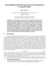
<strong>Stirling</strong> <strong>Power</strong> <strong>Cooler</strong> GPC<br />
gas power cooler<br />
The Gas <strong>Power</strong> <strong>Cooler</strong> (GPC) uses pressurized helium gas<br />
(typically 20 barg) as medium to transfer cold to the application.<br />
as a shield for the 20 K loop, maximizing the cooling power<br />
available to the 20 K target.<br />
The GPC is a two-stage <strong>Stirling</strong> cryogenerator which<br />
simultaneously provides refrigeration at 20 K and at 80 K<br />
by means of two separate heat exchangers. Each of them<br />
consists of a wound spiral tube and a cold gas pump. The two<br />
pumps circulate the gas in seperate loops, from the two heat<br />
exchangers in the application (where energy in injected into<br />
the medium) to the GPC (where energy in extracted from the<br />
medium).<br />
The GPC is connected to the application by two delivery<br />
and return lines ducted together in a single flexible vacuum<br />
insulated line. This offers flexibility for the positioning and<br />
installation of the GPC (up to a radius of 10 meters). In both<br />
the application and transfer lines, the 80 K loop can be used<br />
Operation of the GPC is fully automatic. It runs down to the<br />
lowest possible temperature depending on the application<br />
load. If required, the GPC can be equipped with a set-point<br />
controller that maintains a fixed temperature regardless of<br />
fluctuations in the application load.<br />
The delivery of a GPC system consistst of a two stage<br />
cryogenerator with two cold gas pumps and optional flexible<br />
connection lines.<br />
The figures mentioned below are only an indication, correct<br />
values can only be given after detailed technical discussion and<br />
optimization.<br />
GAS POWER COOLERS<br />
Capacity [W]** <strong>Power</strong> input Cooling water<br />
20 K/80 K 20 K/80 K 30 K/80 K He gas flow [kW] [l/h@15°C]<br />
• GPC-1<br />
75/0<br />
50/400<br />
90/400<br />
Will be a result<br />
11<br />
750<br />
• GPC-2<br />
150/0<br />
100/800<br />
180/800<br />
of customers<br />
22<br />
1.000<br />
• GPC-4<br />
350/0<br />
200/1.600<br />
360/1.600<br />
process conditions.<br />
45<br />
3.500<br />
** simultaneously at 2nd stage ad 1st stage<br />
All specifications at nominal operating conditions. All data are subject to alteration without prior notice.<br />
Pictures are intended to present a general idea of the products.<br />
<strong>Stirling</strong> <strong>Cryogenics</strong> BV, Science Park Eindhoven 5003, 5692 EB Son, The Netherlands<br />
a<br />
company
SC.1.1.1003<br />
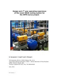
<strong>Stirling</strong> <strong>Power</strong> <strong>Cooler</strong> FF<br />
forced flow liquid cooler<br />
with pump cryostat<br />
The Liquid <strong>Power</strong> <strong>Cooler</strong> - Forced Flow (<strong>LPC</strong>-FF) transfers energy<br />
generated by the customers application (i.e. HTS power cables,<br />
etc.) to the cryogenerator via a closed loop of liquid gas. The<br />
<strong>LPC</strong>‐FF consists of the <strong>Stirling</strong> cryogenerator, a pump cryostat<br />
and connecting lines.<br />
This <strong>LPC</strong>-FF type is effective for those applications where the<br />
application does not allow sufficient cooling by natural flow only.<br />
In this application sub cooled nitrogen (10 - 15 K below its boiling<br />
point) is used. Therefore the heat dissipated by the application<br />
only causes a temperature raise. As there is no boiling there will<br />
be no gas bubbles. This assures that the complete application is<br />
always fully filled with liquid, providing for optimal heat exchange.<br />
The warmed LN 2<br />
(still sub-cooled) re-enters the <strong>LPC</strong>-FF flowing<br />
through a heat exchanger which heats up the buffer serving as a<br />
thermal mass.<br />
In the heat exchanger the LN 2<br />
is cooled down and pumped<br />
through the application again by means of a cryogenic pump.<br />
A second volume is connected parallel to this application loop. This<br />
volume incorporates a heater to increase pressure throughout the<br />
system to ensure that the liquid remains sub-cooled. It also acts<br />
as an expansion vessel to compensate for density fluctuation.<br />
In the buffer tank liquid nitrogen will be boiling. The nitrogen<br />
boil‐off is fed to the <strong>Stirling</strong> cryogenerator through a vacuum<br />
jacketed (VJ) line where it is re-liquefied. The LN 2<br />
flows back to<br />
the buffer through a VJ line by gravity. In order to regulate the<br />
temperature of the buffer the pressure is controlled between 0,2<br />
bar(a) for 65K and 1 bar(a) for 77K. As the heat exchanger between<br />
the buffer tank and the application loop can be considered ideal,<br />
the temperature of the LN 2<br />
at the exit of the heat exchanger will<br />
be the same as the LN 2<br />
in the buffer tank.<br />
The LN 2<br />
exit temperature of the <strong>LPC</strong>-FF is measured continuously.<br />
The cryogenerator capacity is reduced if the temperature starts to<br />
drop and vice versa. This compensates for the heat load variation<br />
of the application.<br />
The system can be equipped with the hardware and software<br />
needed to permit a “soft cool down” from ambient to its operating<br />
temperature and for initial filling and start up. Refrigeration mode<br />
is fully automatic and does not require any operator intervention<br />
to run or regulate it. Manual operation of certain valves is only<br />
needed when modes are changed or in temporary modes.<br />
The cooling capacity of the <strong>LPC</strong>-FF system will depend on several<br />
operating parameters like allowable ΔT across the application and<br />
required ΔP. These conditions and the associated pump losses<br />
result in a calculated flow through the application.<br />
The figures mentioned below are only an indication, correct<br />
values can only be given after detailed technical discussion and<br />
optimization.<br />
NITROGEN<br />
Capacity [W] Liquid gas flow <strong>Power</strong> input [kW] Cooling water<br />
65 K 77 K and ΔP 65 K 77 K [l/h@15°C]<br />
• <strong>LPC</strong>-1 FF<br />
500<br />
840<br />
Will be a<br />
13<br />
12<br />
750<br />
• <strong>LPC</strong>-2 FF<br />
950<br />
1700<br />
result of<br />
26<br />
24<br />
1500<br />
• <strong>LPC</strong>-4 FF<br />
2450<br />
3750<br />
customers process<br />
53<br />
49<br />
3000<br />
• <strong>LPC</strong>-8 FF<br />
4500<br />
7300<br />
conditions.<br />
106<br />
98<br />
6000<br />
All specifications at nominal operating conditions. All data are subject to alteration without prior notice.<br />
Pictures are intended to present a general idea of the products.<br />
<strong>Stirling</strong> <strong>Cryogenics</strong> BV, Science Park Eindhoven 5003, 5692 EB Son, The Netherlands<br />
a<br />
company