The Stabilization of a Landslide Using Trench Drains ... - Harpo spa
The Stabilization of a Landslide Using Trench Drains ... - Harpo spa
The Stabilization of a Landslide Using Trench Drains ... - Harpo spa

You also want an ePaper? Increase the reach of your titles
YUMPU automatically turns print PDFs into web optimized ePapers that Google loves.
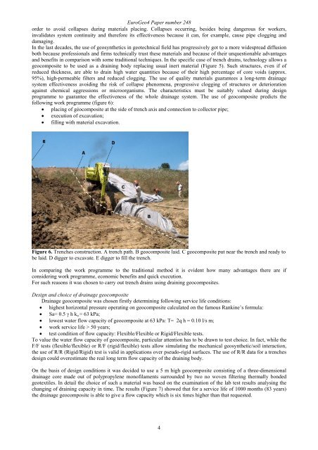
EuroGeo4 Paper number 248order to avoid collapses during materials placing. Collapses occurring, besides being dangerous for workers,invalidates system continuity and therefore its effectiveness because it can, for example, cause pipe clogging anddamaging.In the last decades, the use <strong>of</strong> geosynthetics in geotechnical field has progressively got to a more widespread diffusionboth because pr<strong>of</strong>essionals and firms technically trust these materials and because <strong>of</strong> their unquestionable advantagesand benefits in comparison with some traditional techniques. In the specific case <strong>of</strong> trench drains, technology allows ageocomposite to be used as a draining body replacing usual inert material (Figure 5). Such structures, even if <strong>of</strong>reduced thickness, are able to drain high water quantities because <strong>of</strong> their high percentage <strong>of</strong> core voids (approx.95%), high-permeable filters and reduced clogging. <strong>The</strong> use <strong>of</strong> quality materials guarantees a long-term drainagesystem effectiveness avoiding the risk <strong>of</strong> collapse phenomena, progressive clogging <strong>of</strong> structures or deteriorationagainst chemical aggressions or microorganisms. <strong>The</strong> characteristics must be suitably valued during designprogramme to guarantee the effectiveness <strong>of</strong> the whole drainage system. <strong>The</strong> use <strong>of</strong> geocomposite predicts thefollowing work programme (figure 6):• placing <strong>of</strong> géocomposite at the side <strong>of</strong> trench axis and connection to collector pipe;• execution <strong>of</strong> excavation;• filling with material excavation.Figure 6. <strong>Trench</strong>es construction. A trench path. B geocomposite laid. C geocomposite put near the trench and ready tobe laid. D digger to excavate. E digger to fill the trench.In comparing the work programme to the traditional method it is evident how many advantages there are ifconsidering work programme, economic benefits and quick execution.For such reasons it was chosen to carry out trench drains using draining geocomposites.Design and choice <strong>of</strong> drainage geocompositeDrainage geocomposite was chosen firstly determining following service life conditions:• highest horizontal pressure operating on geocomposite calculated on the famous Rankine’s formula:• Sa= 0.5 γ h k a = 63 kPa;• lowest water flow capacity <strong>of</strong> geocomposite at 63 kPa: T= 2q h = 0.10 l/s m;• work service life > 50 years;• test condition <strong>of</strong> flow capacity: Flexible/Flexible or Rigid/Flexible tests.To value the water flow capacity <strong>of</strong> geocomposite, particular attention has to be drawn to test choice. In fact, while theF/F tests (flexible/flexible) or R/F (rigid/flexible) tests allow simulating the mechanical geosynthetic/soil interaction,the use <strong>of</strong> R/R (Rigid/Rigid) test is valid in applications over pseudo-rigid surfaces. <strong>The</strong> use <strong>of</strong> R/R data for a trenchesdesign could overestimate the real long term flow capacity <strong>of</strong> the draining body.On the basis <strong>of</strong> design conditions it was decided to use a 5 m high geocomposite consisting <strong>of</strong> a three-dimensionaldrainage core made out <strong>of</strong> polypropylene mon<strong>of</strong>ilaments surrounded by two no woven filtering thermally bondedgeotextiles. In detail the choice <strong>of</strong> such a material was based on the examination <strong>of</strong> the lab test results analysing thechanging <strong>of</strong> draining capacity in time. <strong>The</strong> results (Figure 7) showed that for a service life <strong>of</strong> 1000 months (83 years)the drainage geocomposite is able to give a flow capacity which is six times higher than that requested.4