The Stabilization of a Landslide Using Trench Drains ... - Harpo spa
The Stabilization of a Landslide Using Trench Drains ... - Harpo spa
The Stabilization of a Landslide Using Trench Drains ... - Harpo spa

You also want an ePaper? Increase the reach of your titles
YUMPU automatically turns print PDFs into web optimized ePapers that Google loves.
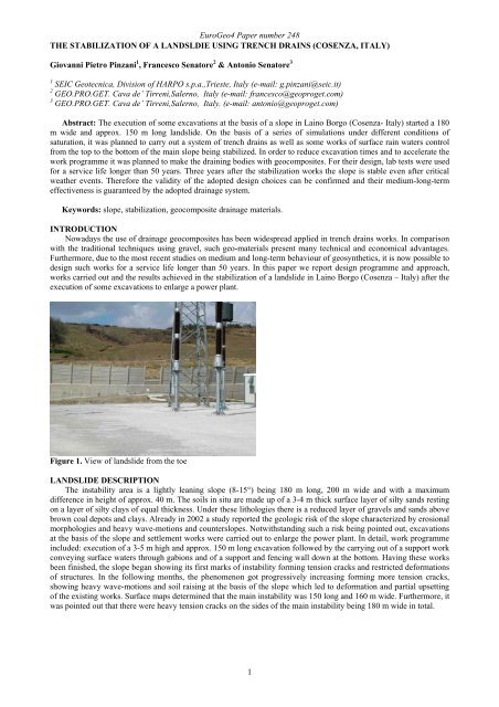
EuroGeo4 Paper number 248THE STABILIZATION OF A LANDSLDIE USING TRENCH DRAINS (COSENZA, ITALY)Giovanni Pietro Pinzani 1 , Francesco Senatore 2 & Antonio Senatore 31 SEIC Geotecnica, Division <strong>of</strong> HARPO s.p.a.,Trieste, Italy (e-mail: g.pinzani@seic.it)2 GEO.PRO.GET. Cava de’ Tirreni,Salerno, Italy (e-mail: francesco@geoproget.com)3 GEO.PRO.GET. Cava de’ Tirreni,Salerno, Italy. (e-mail: antonio@geoproget.com)Abstract: <strong>The</strong> execution <strong>of</strong> some excavations at the basis <strong>of</strong> a slope in Laino Borgo (Cosenza- Italy) started a 180m wide and approx. 150 m long landslide. On the basis <strong>of</strong> a series <strong>of</strong> simulations under different conditions <strong>of</strong>saturation, it was planned to carry out a system <strong>of</strong> trench drains as well as some works <strong>of</strong> surface rain waters controlfrom the top to the bottom <strong>of</strong> the main slope being stabilized. In order to reduce excavation times and to accelerate thework programme it was planned to make the draining bodies with geocomposites. For their design, lab tests were usedfor a service life longer than 50 years. Three years after the stabilization works the slope is stable even after criticalweather events. <strong>The</strong>refore the validity <strong>of</strong> the adopted design choices can be confirmed and their medium-long-termeffectiveness is guaranteed by the adopted drainage system.Keywords: slope, stabilization, geocomposite drainage materials.INTRODUCTIONNowadays the use <strong>of</strong> drainage geocomposites has been widespread applied in trench drains works. In comparisonwith the traditional techniques using gravel, such geo-materials present many technical and economical advantages.Furthermore, due to the most recent studies on medium and long-term behaviour <strong>of</strong> geosynthetics, it is now possible todesign such works for a service life longer than 50 years. In this paper we report design programme and approach,works carried out and the results achieved in the stabilization <strong>of</strong> a landslide in Laino Borgo (Cosenza – Italy) after theexecution <strong>of</strong> some excavations to enlarge a power plant.Figure 1. View <strong>of</strong> landslide from the toeLANDSLIDE DESCRIPTION<strong>The</strong> instability area is a lightly leaning slope (8-15°) being 180 m long, 200 m wide and with a maximumdifference in height <strong>of</strong> approx. 40 m. <strong>The</strong> soils in situ are made up <strong>of</strong> a 3-4 m thick surface layer <strong>of</strong> silty sands restingon a layer <strong>of</strong> silty clays <strong>of</strong> equal thickness. Under these lithologies there is a reduced layer <strong>of</strong> gravels and sands abovebrown coal depots and clays. Already in 2002 a study reported the geologic risk <strong>of</strong> the slope characterized by erosionalmorphologies and heavy wave-motions and counterslopes. Notwithstanding such a risk being pointed out, excavationsat the basis <strong>of</strong> the slope and settlement works were carried out to enlarge the power plant. In detail, work programmeincluded: execution <strong>of</strong> a 3-5 m high and approx. 150 m long excavation followed by the carrying out <strong>of</strong> a support workconveying surface waters through gabions and <strong>of</strong> a support and fencing wall down at the bottom. Having these worksbeen finished, the slope began showing its first marks <strong>of</strong> instability forming tension cracks and restricted deformations<strong>of</strong> structures. In the following months, the phenomenon got progressively increasing forming more tension cracks,showing heavy wave-motions and soil raising at the basis <strong>of</strong> the slope which led to deformation and partial upsetting<strong>of</strong> the existing works. Surface maps determined that the main instability was 150 long and 160 m wide. Furthermore, itwas pointed out that there were heavy tension cracks on the sides <strong>of</strong> the main instability being 180 m wide in total.1
EuroGeo4 Paper number 248Figure 2. Geological and morphological mapGEOTHECNICAL MODELOn the basis <strong>of</strong> geological and geotechnical research, lab tests and surface maps and monitoring, the instabilitywas defined as a surface roto-translational landslide. <strong>The</strong> sliding surface, started by saturation <strong>of</strong> soils characterized bypoor geomechanical properties, was identified at a 3 through 5 depth from the ground level. Two geotechnical unitsand their relative mechanical parameters were established (Table 1).Table 1. Summary <strong>of</strong> geotechnical parametersGeotechnical units Silty clay Clayey sandUnit weight (γ) (kN/m 3 ) 20 18Friction residual angle (ϕ r ) 15 23Cohesion (c r ) 0 0On the basis <strong>of</strong> such, a series <strong>of</strong> simulations with the Limit Equilibrium were carried out by adopting Bishop’s andSimplified Janbu’s theories in order to analyse safety factor values <strong>of</strong> total stability on water level depth changing.From such calculations it was observed that the critical condition (FS=1) took place at an average -2.5 m water depth.Furthermore, it was analysed that decreasing the water level to an average value <strong>of</strong> -3.5 m, the FS value was higherthan 1.15 which means the sufficient condition for an area to be stabilized.Figure 3. Geological section.INTERVENTION CHOICESOnce defined geotechnical mode and instability reasons, it was decided to stabilize the slope through thefollowing interventions:• carrying out <strong>of</strong> a trench drains system;• surface rainfall waters control;• carrying out <strong>of</strong> a gabionade at the slope bottom;• rebuilding <strong>of</strong> the wall parts which were heavily deformed and <strong>of</strong> the fence above.2
EuroGeo4 Paper number 248Figure 4. Plan <strong>of</strong> intervention.Design <strong>of</strong> trench drainsUsually the drainage system is plan to be carried out by placing a series <strong>of</strong> trench drains in a parallel way alongthe slope covering an area wider than the instability to reach the designed water control on the whole interested area.In particular cases, especially when referring to waterpro<strong>of</strong>ing substrate thickness, different geometries can be adoptedaccording to the specific case under studying. In fact, one <strong>of</strong> the main problems in predicting a drainage systemconcerns the placing choice as well as trenches <strong>spa</strong>cing and depth. In the last decades, different studies have beencarried out on that subject in order to analyse both the transitory phase and that <strong>of</strong> steady motion through filteringmotion analysing. Some <strong>of</strong> these studies showed charts determining trench drains depth and <strong>spa</strong>cing according toborder conditions and requested water effectiveness (η). Following these principles and predicting to decrease theslope down to an average depth <strong>of</strong> 3.5 m, a trench drains system was determined with a 2 through 5 m depth placingtrenches along the slope with i= 10 m <strong>spa</strong>cing. To estimate the water quantity to be drained it was cautiouslyconsidered to have average horizontal “k” permeability equals to 1E-03 cm/s and corresponding to a “q” water supply<strong>of</strong> 0.01 1/s sqm <strong>of</strong> excavation walls.Choice <strong>of</strong> materials for draining body<strong>The</strong> most widespread traditional technique to carry out trench drains predicts the execution <strong>of</strong> soil excavation in arectangular or trapezoidal section which will be afterwards filled using permeable material. A first layer <strong>of</strong> gravel set,a draining pipe is placed to help waters flowing and finally the remaining draining material is laid. <strong>The</strong> upper part isthen “clogged” with low-permeable material or more <strong>of</strong>ten with the excavation material itself which is compressed.<strong>The</strong> traditional technique showed in Figure 5 predicts the following work programme:• transport <strong>of</strong> gravel to yard;• execution <strong>of</strong> excavation;• placing <strong>of</strong> no woven geotextiles as filter-separating element;• placing <strong>of</strong> drainage pipe (<strong>of</strong>ten carried out by workers going down into the excavation);• filling with gravel;• upper closing <strong>of</strong> gravel by no woven to avoid clogging;• placing <strong>of</strong> upper soil layer;• transport <strong>of</strong> excavated material to dump.Figure 5. <strong>Trench</strong>es scheme<strong>The</strong> correct carrying out <strong>of</strong> that work programme usually requires relatively long time periods changing according totrench drain depth, yard entering conditions and mechanical properties <strong>of</strong> excavated soil (easy excavation andsidewalls stability). Taking into account that technical times and self-stability times <strong>of</strong> excavation sidewalls arerelatively short, the section must <strong>of</strong>ten be enlarged or strengthened in comparison with previous design planning in3
EuroGeo4 Paper number 248order to avoid collapses during materials placing. Collapses occurring, besides being dangerous for workers,invalidates system continuity and therefore its effectiveness because it can, for example, cause pipe clogging anddamaging.In the last decades, the use <strong>of</strong> geosynthetics in geotechnical field has progressively got to a more widespread diffusionboth because pr<strong>of</strong>essionals and firms technically trust these materials and because <strong>of</strong> their unquestionable advantagesand benefits in comparison with some traditional techniques. In the specific case <strong>of</strong> trench drains, technology allows ageocomposite to be used as a draining body replacing usual inert material (Figure 5). Such structures, even if <strong>of</strong>reduced thickness, are able to drain high water quantities because <strong>of</strong> their high percentage <strong>of</strong> core voids (approx.95%), high-permeable filters and reduced clogging. <strong>The</strong> use <strong>of</strong> quality materials guarantees a long-term drainagesystem effectiveness avoiding the risk <strong>of</strong> collapse phenomena, progressive clogging <strong>of</strong> structures or deteriorationagainst chemical aggressions or microorganisms. <strong>The</strong> characteristics must be suitably valued during designprogramme to guarantee the effectiveness <strong>of</strong> the whole drainage system. <strong>The</strong> use <strong>of</strong> geocomposite predicts thefollowing work programme (figure 6):• placing <strong>of</strong> géocomposite at the side <strong>of</strong> trench axis and connection to collector pipe;• execution <strong>of</strong> excavation;• filling with material excavation.Figure 6. <strong>Trench</strong>es construction. A trench path. B geocomposite laid. C geocomposite put near the trench and ready tobe laid. D digger to excavate. E digger to fill the trench.In comparing the work programme to the traditional method it is evident how many advantages there are ifconsidering work programme, economic benefits and quick execution.For such reasons it was chosen to carry out trench drains using draining geocomposites.Design and choice <strong>of</strong> drainage geocompositeDrainage geocomposite was chosen firstly determining following service life conditions:• highest horizontal pressure operating on geocomposite calculated on the famous Rankine’s formula:• Sa= 0.5 γ h k a = 63 kPa;• lowest water flow capacity <strong>of</strong> geocomposite at 63 kPa: T= 2q h = 0.10 l/s m;• work service life > 50 years;• test condition <strong>of</strong> flow capacity: Flexible/Flexible or Rigid/Flexible tests.To value the water flow capacity <strong>of</strong> geocomposite, particular attention has to be drawn to test choice. In fact, while theF/F tests (flexible/flexible) or R/F (rigid/flexible) tests allow simulating the mechanical geosynthetic/soil interaction,the use <strong>of</strong> R/R (Rigid/Rigid) test is valid in applications over pseudo-rigid surfaces. <strong>The</strong> use <strong>of</strong> R/R data for a trenchesdesign could overestimate the real long term flow capacity <strong>of</strong> the draining body.On the basis <strong>of</strong> design conditions it was decided to use a 5 m high geocomposite consisting <strong>of</strong> a three-dimensionaldrainage core made out <strong>of</strong> polypropylene mon<strong>of</strong>ilaments surrounded by two no woven filtering thermally bondedgeotextiles. In detail the choice <strong>of</strong> such a material was based on the examination <strong>of</strong> the lab test results analysing thechanging <strong>of</strong> draining capacity in time. <strong>The</strong> results (Figure 7) showed that for a service life <strong>of</strong> 1000 months (83 years)the drainage geocomposite is able to give a flow capacity which is six times higher than that requested.4
EuroGeo4 Paper number 248Figure 7. Test results <strong>of</strong> variation flow capacity in the time at 50 kPa (Colbond).FURTHER WORKSBesides trench drains at the bottom <strong>of</strong> the slope, it was carried out a system <strong>of</strong> gabions and a perforated pipe topick up and convey waters from trench drains themselves. Above such structures and always in gabions a smallsupport wall and a channel drain were built. Two further surface waters ditches were out along middle and top slopethrough small drains waterpro<strong>of</strong>ed by LDPE geomembranes. In the end, it was predicted to rebuild the parts <strong>of</strong> thewall damaged by landslide in reinforced concrete.RESULTConsolidation and drainage works finished, the slope got stable without showing any slope motion. Surfacemorphologies <strong>of</strong> landslide were afterwards changed by agriculture and up till now there have not been any marks <strong>of</strong>tension cracks, store or motions pointed out. After three years from the intervention, such a condition <strong>of</strong> equilibrium isstill stable. <strong>The</strong> carried out structures have not undergone any damage or deformation and the unloading <strong>of</strong> drainagesystem has been working even in drought periods.Figure 8. Actual stage.CONCLUSIONS<strong>The</strong> examined intervention has pointed out how the stabilization <strong>of</strong> a slope through trench drains can be carriedout using drainage geocomposites. <strong>The</strong> design and choice <strong>of</strong> geocomposite require the analysis <strong>of</strong> its short and longtermproperties particularly referring to the changing <strong>of</strong> its drainage capacity in time. Such a datum can be deducedfrom R/F or F/F tests in order to simulate real tensile conditions between soil and geocomposite. Finally, the carryingout <strong>of</strong> trench drains using geocomposites instead <strong>of</strong> the traditional gravel gives important technical and economicaladvantages.Acknowledgements: <strong>The</strong> authors wish to express special thanks to Mrs Annalisa Rondi for the English editingsupport.Corresponding author: Mr Giovanni Pietro Pinzani, harpo s.p.a., via torino, 34, trieste, italy, 34100, Italy. Tel:+390403186611. Email: g.pinzani@seic.it.REFERENCESBottcher, R.D. 2006. Long-term flow capacity <strong>of</strong> geocomposites. 8 th International Conference on Geosynthetics,Yokohama, Vol. 2 pp 426.Desideri, A., Miliziano, S., Rampello, S. 1997. Drenaggi a gravità per la stabilizzazione dei pendii. Hevelius Edizioni.Koerner, R.M. 1994. Designing with Geosynthetics. 3 rd edition. Prentice Hall.5