
Create successful ePaper yourself
Turn your PDF publications into a flip-book with our unique Google optimized e-Paper software.
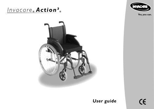
IntroductionDear CustomerThank you for purchasing an Invacare wheelchair.This model was designed to provide you with all the benefits and features to meet your needs. Only qualitycomponents were selected for your wheelchair based upon rigorous inspections during the entire manufacturingprocess.This manual describes the operating limits of your wheelchair, maintenance operations and adjustments thatyou or your assistant can make.However, all the repairs (except for inner tubes) as well as some adjustments, require specific technicaltraining and, therefore, must be performed by your distributor.The I nv a c a re ® Action³ ® is designed for both indoor and outdoor use with the purpose of helping peoplewho are not able to walk over a long distance.
1.1.1 Leaning forwardDo not extend your chest over the armrest (figure 4).In order to reach an object in front of you, you must lean andbend down ; therefore, you must use the castors as a tool(pointing them forward) to maintain stability and balance. Anaccurate alignment of the wheels is essential for your safety(figure 5).1.1.2 Leaning backwardPosition wheelchair as close as possible to the desired objectso that you can simply pick it up by stretching your armwhile sitting in the chair in a normal position. In any case, donot lean backwards because you may cause the chair to tip(figures 6 and 7).445 67
1.2 Sideways transferring to other seatsThis may be done without assistance provided that you aresufficiently mobile and have a strong enough torso.- Move the wheelchair as close as possible to the seatto which you would like to sit, with the castors pointedforward. Lock the wheels by applying the brakes. Move theweight of your body towards the seat (figure 8)- While moving from the wheelchair to the seat, your bodywill have little or no support. Where possible use a transferboard during transfers.- If you are more or less able to stand up and if your upperbody is sufficiently strong and mobile, you can transferforward to another seat. Fold the footplate up and push thefootrest/legrest to the side, bend your body forward leaningon the two armrests and lift yourself up; then shift yourbody towards the place where you want to sit while distributingyour weight to the arms and hands (figure 9).! Warning :- Position yourself as close as possible to the place whereyou wish to sit.- When transferring, position yourself as far back as possiblein the seat to prevent breaking screws, damaging the seatupholstery or causing the wheelchair to tip forward.- Lock the two brakes ; they should not be used in any caseas support for transfers.- Never stand on the footrests when you are getting in orout of the wheelchair (figure 10).58 9 10
61.3 Tilting (balancing on the rear wheels)For greater safety, this operation must be performed by anattendant. The attendant should be aware of the requiredphysical effort and use appropriate positioning in order torelieve the strain on his/her back (keep a straight back andbend your knees during this operation).To tilt the wheelchair, the attendant must firmly grab the handlesmaking sure both are properly fixed. Warn the occupantin the wheelchair before tilting it and remind him / her tolean backwards and make sure that both feet and hands ofthe user are clear of the wheels.Place a foot on the footstep tube and move continuouslyuntil the chair reaches the equilibrium point. At this stage, theassistant will feel a difference in weight distribution, whichusually occurs at approximately 30°. At this point, thewheelchair can get over the obstacle easily.Finally, the attendant slowly and gradually lowers the frontdown to the ground, while firmly holding the handles.1.4 Tilting, KerbsTo get on the pavement :- Method 1 (figure 11)The attendant positions the wheelchair in front of thepavement facing forward. Attendant tilts the wheelchairbackwards until the castors reach the pavement; attendantpushes the wheelchair forward until the rear wheels areagainst the kerb and again pushes the wheelchair until therear wheels climb over the kerb.- Method 2 (figure 12)In this case, the attendant stays on the pavement andmoves the wheelchair in a backwards position with the rearwheels against the kerb. The attendant tilts the wheelchairbackwards until it is balanced and pulls the wheelchair with asteady movement until the rear wheels climb over the kerb ;then he / she lowers the castors, while making sure that thechair is far enough on the pavement so that the castors donot fall into empty space.! Warning :- Be aware of detachable parts such as armrests or legrests :they must NEVER be used as lifting supports as they may beinadvertedly released, resulting in possible injury to the userand / or attendant.- Do not lower the wheelchair suddenly, even if it is severalcentimetres from the ground, as this may result in injury ofthe user.11 12
To get off the pavement :The attendant positions the wheelchair facing forward onthe pavement and tilts it backwards until it is balanced, thenhe/she pushes the wheelchair forward until the rear wheelstouch the road after getting over the obstacle; then, he / shegradually lowers the castors to the ground.1.5 StairwaysBecause this is a difficult movement, we recommend usingtwo attendants, one in front of the wheelchair and onebehind the wheelchair.To climb stairways (figure 13) :After tilting the wheelchair to the point of equilibrium, oneassistant (at the back) holds the wheelchair up against thefirst step grasping the handles firmly to lift..The second assistant, lifts the wheelchair above the stairs,while holding firmly a fixed part of the frame, and holds itwhile the first assistant takes a step and repeats the operation.The wheelchair must not be lowered until the last step hasbeen passed and the chair is clear of the stairs.To descend stairways :Same operation as above, however, in reverse order.! Warning :- Do not attempt to lift the wheelchair by any removableparts (such as armrests, legrests or footrests).- Avoid using an escalator which may lead to serious injuryin the event of a fall.1.6 SlopesIt is recommended to avoid using ramps with a slope higherthan 9°. The wheelchair risks tipping over in the event ofspinning or side movement (figure 14).713 14
8Upward slopes (figure 15) :Lean the upper body forward and move the wheelchairforward with short quick pushes on the hand rims to maintainspeed and direction control. If you want to rest, applyboth brakes when stopping.Downward slopes (figure 16) :Lean backward cautiosly and let the hand rims slide in yourhands. Be ready to react at any moment to control speedand direction.! Warning :- Avoid turning suddenly and never try to climb and descenda ramp diagonally (figure 17).2. Operating instructions2.1 Unfolding and Folding the wheelchair2.1.1 Unfolding the wheelchair (figure 18) :- With one hand, grab the armrest or the seat supporttube on one side of the wheelchair and slightly tilt it towardsyou (so that the rear wheel and castor lift from theground) ;- With the other hand, push on the seat upholstery untilthe tube supporting the upholstery is fully unfolded. Theseat upholstery must be fully extended ;- Then, engage the two manual brakes, open the footrest/legrest and check the ground clearance (footrest/grounddistance - see § B-2.1.4). You can now sit down in thewheelchair.1516 1718
2.1.2 Folding the chair (figures 19 and 20) :- Fold and lock the footrest/legrest toward the front of thewheelchair.- Swivel the plates into the vertical position. Using bothhands, take the centre front and back edges of the seatupholstery and lift it. Or, tilt the wheelchair to one sideand close it using the handles on the backrest.! Warning :- Fold the wheelchair while keeping the seat upholsteryupwards to avoid damage by the folding system.2.2 Wheelchair propulsionWheelchair propulsion is provided by the handrims mountedon the wheels. The handrims can be adjusted basedupon your height to allow you to hold them properly, andvarious accessories can be added to improve the grip (antislipplastic coated, capstan spigot kit, etc.)Qualified medical and paramedical staff will be able toprovide you with advice regarding the propulsion which isbest adapted to your disability.919 20
103. Safety inspection and maintenance3.1 Performance controlAs the user, you will be the first to notice the possibleoperational defects of your wheelchair. The following tableindicates the easiest troubleshooting symptoms to identifyand the preliminary inspection that you can perform.In the event that the symptoms persist after adjusting thepressure in the tyres and tightening screws and nuts, pleaseconsult your retailer.The inner tubes of the wheels are the only components thatyou can repair yourself (see § B-2.3).Thewheelchairswervesto the rightThewheelchairswervesto the leftThewheelchairturns ormoves slowlyThecastorsliftCreakingandclinkingPlay inthewheelchairInspectionsMake sure that pressurein the pneumatic tyreis correct(cf. § B-2.3)Make sure that the boltsare tightCheck the adjustmenton the fork angleMake sure that the 2castors come in contactwith the ground at thesame time3.2 General inspectionYour distributor, who has the required technical expertise, isresponsible for any wheelchair repairs.We recommend that you take the wheelchair to yourretailer at least once a year for a complete inspection. Regularmaintenance allows the identification and replacement ofdefective and worn parts, which improves the daily operationof your wheelchair.Regular inspections to be performed by you or yourassistants :a. GeneralMake sure that the wheelchair folds and unfolds easily.Make sure that the wheelchair moves in a straight line. (noresistance or deviation)b. Manual brakesMake sure that the manual brakes do not touch the movingtyres.Make sure that the manual brakes operate easily.Make sure that the joints are not worn and do not haveexcessive play.c. Folding systemCheck the folding system for worn or distorted parts.d. Skirtguard/armrest upholsteryMake sure that all the fittings are properly tightened.e. ArmrestsMake sure that the armrests are firmly attached, but easy toremove.
f. ArmpadMake sure that the armpads are in good condition.g. Seat and backrest upholsteryMake sure that the upholstery is in good condition.h. Rear wheelsMake sure that the wheel nuts and precision bearings aretight.Make sure that the wheels are parallel to the frame.i. HandrimsCheck for rough patches.j. SpokesMake sure that the spokes are not distorted, loose or broken.k. CastorsMake sure that the axle is tight by turning the wheel thewheel must gradually come to a stop.l. Fork/steering tubeMake sure that all the fittings are well tightened.m. Pneumatic and solid tyresCheck the pressure of the pneumatic tyres (value indicatedon the side) check the wear of the solid tyre tread.n. MaintenanceDo not use any product to clean parts except for theupholstery which can be washed with soap and water only.Make sure you dry the wheelchair if it is wet (e.g. afterwashing it or going out in the rain).Avoid riding on wet areas as well as gravel, grass, etc. (warning:sand and sea water particularly damage ball bearings).When using the wheelchair inside, we recommend usingsolid tyre castors, especially when riding on carpet.Do not expose the wheelchair to a temperature higher than40°C (e.g. in a vehicle).4. TransportationTransport of wheelchairs in vehiclesThe Invacare® Action 3 has been tested for safety in collisionsaccording to ISO-7176-19:2001, Invacare® Action 3 canbe used for transport in vehicles that have been speciallyadapted for this purpose. The wheelchair must be securelyfastened in the vehicle according to the methods describedon the following pages.Remember that the best solution is always to movethe user from the wheelchair into a normal car seat.4.1 Test report from dynamic safety restraint test(ISO-7176-19)Test no : P500846A (fixed backrest) & P5000846B (reclinerbackrest), Customer : Invacare Rea AB, Date : 2005-01-21Testing to be carried outPulse specification : ISO-7176-19Wheelchair Manufacturer :Invacare France Opération SASModel : Action 3Weight : 14.5 kg (fixed) 16,5 kg (recliner)Configuration : Forward facing11
12Safety restraint device Manufacturer : Unwin SafetySystemsModel : 4 Pt WWR/ATF/K/RAttachment device : Unwin Low Profile RailUser safety belt : Manufacturer: Unwin Safety SystemsModel : 3 Pt WWR/HD/ATF/K/RTest dummy : Hybrid IIIWeight : 76.5 kgTest configurationChassis : Height 46 cmBackrest : Fixed/ReclinerSeat : sling typeArmrest : Height adjustableLegrest : Sxing in/swing outRear wheel : 24" pneumaticCastor : 8" x 1/4" solidAccessories : Heel strapTested : 2005-01-21The safety restraint devices used in this test must be approvedaccording to ISO-10542. We have chosen to work with Unwin,a well-known quality manufacturer of safety restraint devicesfor wheelchairs.4.2 Observations before transport of wheelchairs invehicles• We recommend that wheelchair users should transfer to theseat of the vehicle and use the installed restraint system of thevehicle whenever feasible.• The wheelchairs are tested in a basic configuration. The usein other configurations has not been tested. See user manual,section «Test report from dynamic safety restraint test», fortest configuration.• Auxiliary wheelchair equipment is either secured to thewheelchair or removed from the wheelchair and secured inthe vehicle during transit. (i.e. table trays).• Alterations or substitutions are not to be made to points ofthe wheelchair or to structural and frame parts without thewritten consent of Invacare® .• A wheelchair-anchored pelvic belt must be fitted across thewheelchair occupant in addition to the lap and diagonal andrestraint (3-point belt).• Belt restraints are not to be held away from the body bywheelchair components or parts such as armrests, posturalrestraints, wheels, etc. (Picture 22)• The wheelchair must be securely fastened in the vehiclewith an ISO 10542-2 approved 4-point belt system, accordingto the methods described in the manual.• The occupied wheelchair must be tied down in an forwardfacingconfiguration, with the parking brake applied.• The test dummy weight is 75 kg, according to ISO 7176-19,although the chairs are approved for users up to 125 kg.• The wheelchair backrest should be positioned as close aspossible to 90 degrees.• If possible, a headrest should be used during transit, inorder to reduce the risk of neck unjury. The headrest shouldbe placed as high as possible.Please observe that even if these products and recommendationsare provided in order to increase security and safety,
injury to vehicle occupants still might occur in the event of acollision or other accidents and no guarantee is givenin this respect.Correct and Incorrect placements of belt (picture 21)4.3 Restraint methods (picture 22)A. Frontal restraints with straps1. Connect the frontal straps around the frontal part of theframe.2. Release brakes and tension front straps by pulling thewheelchair backwards from the rear.3. Re-apply wheelchair brakes.B. Rear restraints1. Attach the snap hooks on the rear straps to the frame justabove the rear wheel attachments.2. Tighten the straps.C. Fastening of pelvic belt and safety belt1. Check that the pelvic belt on the wheelchair is correctlyfastened.2. Fasten the 3-point safety belt over the user.If pelvic belt on the wheelchair is missing we recommend thatthe user should transfer to the seat of the vehicle, if possible.The safety belt should not be kept from the user’s body bythe parts of the wheel chair.D. Pelvic belt1. The pelvic belt is mounted on the backrest brackets(picture 23).22212313
145. Summary of warranty terms5.1 Standard Invacare terms and conditionsThis is to certify that your manual wheelchair is warranted byInvacare for a period of 2 years for the frame and crossbars,all others parts one year, subject to the following conditions :- Only wheelchairs purchased at the displayed price recommendedby Invacare are covered by the Invacare warranty.- If a defect or fault is discovered the supplier / dealer fromwhom the appliance was purchased should be notified immediately.- The manufacturer will not accept responsibility for damagecaused by misuse or non-observance of the instructions setout in the user manual.- During the period of warranty, any parts that have becomedefective due to faulty workmanship or materials, will berenewed or repaired without charge by the Invacare dealer/supplier.- The warranty will be forfeited should any unauthorisedalteration be made to the equipment.- The Purchaser’s statutory rights under the ConsumerProtection Act are not affected.5.2 Limitation of liabilityThis warranty does not extend to the consequential costsresulting from fault clearance, in particular freight and travelcosts, loss of earnings, expenses, etc.Invacare shall not be liable for :- Natural wear and tear.- Inappropriate or incorrect use.- Defective assembly or setting-up by the purchaser or thirdparties.- Defective or neglectful treatment use of unsuitable spares.6. Summary of operating instructions foroptimal safety- Maximum user’s recommended weight : 125 kg.- Do not attempt to reach objects if you have to moveforward in the seat.- Do not attempt to pick up objects from the floor by reachingdown between your knees.- Do not lean over the top of the upholstery back to reachobjects located behind you : this may cause you to tip over- Always engage both manual brakes simultaneously.- Manual brakes are parking brakes : they must not be usedin any case to slow down the wheelchair or as supportduring transfers.- Do not tilt the wheelchair (down kerbs or steps) withoutusing an assistant.- Do not carry in the stairways or escalator, user sited inthe wheelchair whith only one attendant; this may causeserious injury.- Do not use the wheelchair unless it has the proper tyrepressure as indicated on the side wall of the tyre.- Do not overinflate the tyres : this may cause the tyres toexplode and cause bodily harm.- Do not expose the wheelchair to a temperature higherthan 40°C.- To avoid injury, keep your fingers away from mobile parts(armrests, folding system, legrests/footrests), and maintaingood posture before lifting the wheelchair.
B. DESCRIPTION OF YOUR WHEELCHAIR1. PRESENTATION1.1 IntroductionYour wheelchair has been factory set before you purchasedit. However, it must be specifically adapted to your needs.The following detailed paragraphs describe the variousfunctions and possible adjustments as well as availableoptions. You can make some adjustments yourself, whileothers can be made only by your dealer.Important: based upon the selected model or options, yournew Action3 wheelchair may be equipped with all of thecomponents or options which are described in thefollowing pages.! This is a warning symbol ; you mustimperatively follow the instructions thatare provided in these paragraphs toprevent personal injuries as well asinjuries to people around you !1.2 General description (see photo)Your wheelchair is made of various parts and this manualdescribes only the main parts. We recommend that youbecome acquainted with the following terms in order tobetter understand your wheelchair operation : The seat consists of the seat and backrest upholstery,the backrest and armrests. This unit is designed to provideoptimal comfort. The swing-away footrest support or legrest : thisis the supporting part between the frame and the footrestwhich swivels to facilitate transfers and can be removedduring transport. The footrest consists of an adjustable tube and thefootplate which supports the foot. The folding frame consists of side frames and a foldingsystem including the seat rails. These parts constitute theframe, which is the supporting component of the wheelchairand its strength is well tested (checked at 125 kg). The steering tube is the connection between frame andcastors ; it allows the adjustment of the seat angle. The rear wheel consists of the wheel, axle and handrim.The rear wheels ensure the rear stability and allow thepropulsion of the wheelchair using the handrims. They aremounted on the multiple adjustment wheel support brackets.15
16 The castor consists of the front wheel and the fork. Thecastors provide front contact with the ground and determinethe steering by the direction of the forks. The manual brake is a parking brake. The two manualbrakes are used to secure the wheelchair when staionary.Backrest upholsteryBackrestRear wheelRear wheelsupportRear wheel axleArmpadArmrestSeatupholsterySwing awaylegrestAdjustablefootrest tube2. Adjustments2.1 Seat2.1.1 Seat upholstery- Standard seats• Nylon upholstery seat with or without Velcro fastener : theVelcro fasteners are required for the proper positioning ofthe cushion (photo 1) ; please make sure that the cushion isproperly positioned on the seat.• Padded seat : it provides comfortable support to the user. Standard seats are not adjustable; in the event that theybecome slack, it is recommended to request your dealer toreplace them.! Always use upholstery equipped with Velcro fastenerswhen you have a cushion in order to prevent sliding. Invacare provides a wide range of seat cushions adaptedto your needs. Please contact your dealer.HandrimManualbrakeFoldingframeSteering tubeFront wheelSwing awayfootrestFootplate1
- Rigid seats :• Comfort and toilet seats (photo 2) : they are removableallowing the folding of the wheelchair, simply lift the seat andput it away, then take hold of the 2 seat rails and pull themupwards. Repeat the operation in reverse order to unfold thewheelchair (see § 2.1.1). The upholstery and casing of the two seats will wear,please contact your dealer for possible replacement.! Make sure that the seat is properly positioned on the 2seat rails to provide safety and comfort for the user.Keep your fingers away from movable parts to preventinjuries during folding and unfolding !2.1.2 Type of backrests- Fixed backrests :• Fixed backrest of 0° and 7°; these two backrests do notrequire adjustments, they can be equipped with paddedbackrest or tension-adjustable backrest (optional, see §2.1.3). The 7° version can be optionally equipped with heightadjustable push handles which provide better comfort for theattendant.- Folding backrest (photo 3 and 4)43 or 51 cm backrest height.• To save space during transport, operate lever (A) by pullingor pushing it and fold the top of the backrest.To return to the initial position, bring the top in the verticalposition; it locks automatically.! Always make sure that the backrest is properly lockedin place before the user settles down in the wheelchair toprevent any injuries !A1723 4
18- Reclining backrest 0° - 30° - 43 or 51 cm backrest height.Angle can be adjusted very easily which provides a comfortablerest position :Simultaneously pull the levers (A) to provides the same angleon both sides, release the levers when you reach the desiredangle.(Photo 5) Mechanical versionThere are 4 angles position by step of 10°.Note : Push on the backrest canes before operating thelevers, this is to release the auto-locked security system.(Photo5A). Gas strut version (0° to 30° continuously (Photo 6).Pneumatic jacks provides help to raised the user by the attendant,always operated with the user sited in the wheelchair.! It is recommended that this operation be performedonly by the attendant. Always make sure that the backrest islocked in place to ensure perfect safety for the user.Keep away fingers from moving parts (levers, cylinders,mechanisms, etc.) to prevent injuries !Avoid operating levers (A) (photo 6) during a sideways transfer,for example, in order to prevent destabilising the user’s position!To ensure safety for the user, when backrest is reclined, werecommend to use anti-tippers (available as an option). Maintenance of reclining backrest mechanism varies withuse. Please contact your Dealer.Based upon the development of your disability, you canchoose an Action 3 backrest that meets your needs. Pleaseconsult with your Dealer.1AA255A66A
• Fixed backrest with mid-height angle adjustment (photo 6B);the angle can be adjusted using the different holes on thebackrest support (shema 6C), remove screw (A) and nut (4mm Allen key and 10 mm spanner), select the desired angle(from -6° to + 24°, every 6°), repositioning the screw (A) andfirmly re-tighten. The push handles are height adjustable, slightlyloosen the knob (B), adjust to the desired height, firmlyre-tighten.! Always make these adjustments before the usersettles down in the wheelchair to prevent injuries !2.1.3 Backrest upholstery- Standard upholstery backrests• Padded backrest it provides excellent daily comfort for theuser who does not need specific support for the upper body. In the event that the upholstered backrest slackens, ask fora replacement from your Dealer.BA_++24°+18°+12°+6°-6°0°• Tension adjustable backrest (photo 7) it allows adjustmentof the backrest curvature based upon user’s body posture.Lift the flap (A) and pull the straps (B) in order to stretch orslacken them. Each strap can be adjusted separately.Reposition the flap (A).! Check the quality and positioning of the Velcro fasteners.Always make this adjustment before the user settlesdown in the wheelchair to prevent injuries !- Rigid backrest (photo 8) the rigid canopy and preformedfoam cushion provide optimal comfort. The backrest isremovable allowing the wheelchair to fold loosen the twobuttons (A), slide the levers (B) to the inside and disengagethe hooks (C) from their supports. Reverse the procedureto reassemble the backrest.! It is recommended that this operation be performedonly by the attendant. Always make sure that the backrest islocked in place for optimal safety of the user.Keep fingers away from movable parts to prevent injuries !ABBAC196B6C78
202.1.4 Footrest supports- Standard footrest supports (photo 9) they swing away duringtransfers and can be removed during transport.Operate lever (A) by pushing sideways and swivelling towardsoutside or inside in case there is not enough space. To returnto the initial position, align the footrest support it locksautomatically.To remove the footrest support, simply pull up afterunlocking the assembly. Reverse the procedure to reassemble,while still in the unlocked position.- Legrest (photo 10) performs the same operation as for thefootrest support to swing away or remove the legrest, byoperating lever (A) which unlocks the locking system.To adjust the angle, support the leg with one hand whileloosening the locking knob (B) with the other hand. Lift orlower the legrest in the desired position and firmly tightenthe knob (B).The calfpad swings away during transfers and is heightadjustable by sliding. After loosening the screw (C), adjustto the desired height and firmly tighten the screw (C). Inaddition, it is depth adjustable loosen the screw (D), bring tonew position and firmly tighten the screw (D).ABA9 D C10
- Footrests (photo 11 & 12) : the footplate can be lifted duringtransfers footrests are height adjustable and can be equippedwith a fixed or articulated footplate (optional). Loosen thescrew (A) to adjust to the desired height, firmly tighten thescrew after adjustment.The footplate can be articulated by indexed plate (optional)loosen the screw (B), adjust to the desired angle and tightensecurely.- Straps : to ensure a good position of the feet, two types ofstraps can be provided; the heelrest strap (plain or adjustableby Velcro fasteners) and the calfpad strap attached to the footrestsupport are both adjustable by Velcro fasteners.2.1.5 Armrests- Removable :• Simple [1] (photo 13 and 14) : to remove armrests, simplypull them up. Previously, press on the push pin (B) locatedat the bottom of the armrest vertical upright. Reverse theprocedure to reinstall them. To adjust their height (3 positions),remove the screw (A), adjust to the desired height andreposition the screw (A), tighten without forcing.Note : the standard footrest supports and legrests are mountedin pairs on the wheelchair; whenever you remove them,remember that you have a right side and a left side !! Never lift the wheelchair by the footrest supports orlegrests !Keep your fingers away from movable parts during folding,disassembling or adjustment to prevent injuries !21A11 B 12A13B14
22- Swing-away and removableThis range of armrests can be swung away to facilitatetransfers and disassembling during transport.• Simple [2] (photo 15) to swing the armrest away, push downthe dog point (A), reverse the procedure to reinsert makingsure that the dog point (B) is properly engaged in its housing.To remove the armrest, swing it back completely and pull itup. Reverse the procedure to reinstall.- Ajustable tubular [3] (photo 16) :• AdjustableIdentical to the previous procedure including armrest heightand depth adjustment ; slightly loosen the ball screw (B), adjustfor the desired height based upon the preset holes and firmlytighten the screw ; slightly loosen the two screws (C) andslide the armrest down for the desired depth, firmly tightenthe two screws (C).- Adjustable monobloc [5] (photo 17) :To swing the armrest away, activate the grey trigger (A). Toautomatically reinsert it swing it down and make sure that theguide (B) is properly engaged in its housing.To adjust the armpad in height and depth, proceed as theadjustable tubular armrest procedure.Note : the armrests are mounted in pairs on the wheelchair ;whenever you remove them, remember that you have a rightand a left side !! Never lift the wheelchair by the armrests !Keep your fingers away from movable parts during folding,disassembling or adjustment to prevent injuries !ACAB 15 B16 B17
2.2 Frame2.2.1 SidesThe sides or side frames are designed to accommodate thesteering tubes for the castors and multiple adjustment wheelmounting for rear wheels.These wheel mountings allow five height positions and threelongitudinal positions (Active = advanced for better handling ;Standard = serial delivery; Amputee = backward for better stability,serial with reclining backrest).2.2.2 Folding systemIt consists of two cross-bars which integrate the seat rails.To fold and unfold your wheelchair, see chapter A “ General ”paragraph 2.1.2.2.3 Steering tubesThey provide seat dump (0°, 3° or 6°) based upon user’s capacity,propulsion, desired floor-to-seat height and selected front andrear wheels. All these adjustments and changes of position must be performedby a professional technician upon agreement by yourprescribing physician. Please consult with your dealer.Active position is only compatible with 6'' front castors.In "Active" position, it is necessary to use anti-tippers to avoidany risk of tipping backwards when you drive on a slope ! (See §2.6.3)2.3 Rear wheels2.3.1 WheelsThe 24" (610 mm) rear wheels are spoked or compositewheels; the 22" (550 mm) wheels are only spoked wheels.They can be delivered with pneumatic or solid tyre.The 24" spoked wheels can optionally accommodate spokeguards to prevent injuring the fingers during propulsion.A flat tyre (photo 18) must be removed in order to berepaired. Remove the rim assembly (tyre and inner tube),repair or replace the inner tube, reinsert in the tyre andreposition the assembly on the rim.23! In "Active" position, the manual brake may unlock afterswinging the footrest support out.In this particular case, we recommend to swing the footrestsupport inside !18
24Comply with the inflation pressure specified on the sidewallof the tyre.Note : remember that in order to maintain the interchangeabilityof the chair wheels equipped with quick-release axles,the pressure in the two tyres should be the same.! Never exceed the pressure specified on the sidewalls ofthe tyre, otherwise, the tyre may explode and cause injuries ! Pneumatic tyres wear out. In addition, the roughnessof the ground surface and driving have an impact on theirlongevity. Replace them regularly to avoid trouble caused bypuncture.Please consult with your Dealer.2.3.2 HandrimsThey provide the wheelchair propulsion. They can be madeof anodized aluminium, chrome steel or coated with nonslipplastic (optional).Note : A handrim with spigot kit (photo 19) for people whohave grasping difficulties is available optionally. The mounting and positioning must be performed by aprofessional technician upon agreement by prescribingphysician. Please consult with your dealer.! Handrims are constantly in contact with your hands.Make sure that they are not damaged !19
2.3.3 AxlesThe axles connect the wheels and frame. Fixed and quick-releaseaxles are available- Fixed axles: regularly check the axle tightening.- Quick-release axles (photo 20) : depress the button (A) andinsert the axle in the wheel hub. Position the assembly in thebearing (B) of the multiple adjustable wheel mounting untilit locks in place. The locking balls (C) must rise above thebearing. No significant side clearance is allowed.To reduce clearance as much as possible (photo 21), removethe axle and adjust the nut using a 19 mm key ; then block theaxle with an 11mm open-end key.! Make sure that the axle and the locking balls are clean.To prevent falls, it is essential that the button (A) and thelocking balls (C) are disengaged providing a perfect lock of therear wheels.The quick release axle is a precision part, take care of shocks andclean regularly to ensure the good working of the mechanism.2.4 Castors2.4.1 WheelsThe front wheels are available in 8" (200mm) diameter and intwo widths, 1 3/8" (32 mm) and 2" (50mm), or in 6" (150mm)diameter and a single width of 1 3/8" (32mm). They can bedelivered with pneumatic or solid tyre.Note : refer to paragraph 2.3.1. for regular maintenance.2.4.2 ForksDifferent fork positions are available based upon the selectionof floor-to-seat height, castors and rear wheels. Please take advice from your dealer, if you want to replacea fork or the castors or rear wheels.25BADCA2021
262.5 Brakes2.5.1 Manual brakesThe manual brakes (photo 22) are designed to secure thewheelchair during long stops. They are not intended to slowdown the wheelchair or to be used as support during atransfer. They must be operated simultaneously.In order to brake, push the handle (A) forward. The handlefolds back to facilitate transfers. Draw as a preliminary thehandle upwards ! Once the brakes are engaged, the wheelchairshould not move at all.Note : brakes adjustments are based upon the diameterand type of the wheels. After repairing a flat tyre or in theevent of wear of the pneumatic or solid tyre, you may needto adjust the brake(s). To adjust the brake(s), loosen thetwo screws (B) and slide the brake assembly to obtain thefollowing value between the wheel and the brake shoe inunlocked position :Solid tyre X = 6 mm, Pneumatic tyre X = 5 mm! Firmly tighten the screws (B) after adjustment.Keep your fingers away from movable parts to prevent injuries !A2.5.2 Hub brakesBesides the functions provided by manual brakes, the hubbrakes provide the slow down (for example, on a slope) andimproved safety because they are still efficient when youhave a flat tyre !Two versions are available: (photos 23 & 24) attendant controland dual control (attendant and user).To slow down, gradually pull the lever (A) upwards.To lock the brake in parking position, with the lever (A)tightened, push the lock (B) to engage it in the notches ofthe brake handle ; then pull the lock up to unlock.To adjust braking : turn the screw (C) counterclockwise toincrease braking force and turn clockwise to reduce it. The specific adjustments of hub brakes must always beperformed by your Dealer.! Always operate the two brakes simultaneously and donot take slopes exceeding 5% to ensure perfect control ofthe wheelchair steering !BCXAB222324
2.6. Options2.6.1 Seating options- Anatomic headrest (photo 25 and 26) : it is mounted onthe back brace (described below) by means of a multipleadjustment mounting.This mounting allows you to adjust the height, angle andsides using a two levers (A and A') ; the cushion is alsoangle-adjustable by operating the lever (B).Note : make sure that you properly position the indexablelevers so that they are not in the way or causing injury forthe user or attendant.! Do not adjust this option when the user leans over andmake sure that their mounting to the backrest is correct toprevent injuries.- Back brace (photo 27) : it provides tension to the backrestupholstery and provides the attendant better ergonomicswhen pushing the wheelchair.Note : it swings away to facilitate the wheelchair folding;slightly loosen the button (A), pull up and swivel along thebackrest until it is in vertical position.To reposition it, reverse the procedure and firmly tighten thebutton (A) making sure that the button is properly tighten(B).! Do not lift the chair by handling the back brace. Thereis a risk to unlocked the back brace by push it up. Keep yourfingers away from movable parts to prevent injuries.2725BBAA'A2627
282.6.2 Propulsion options- Transit version (photo 28) : the wheelchair is designed to bedriven only by the attendant. To facilitate sideways transfersand save space, the wheelchair is equipped with rear wheelsof 12" (315 mm) with pneumatic or solid tyre.The manual brakes (optional hub brake) are only accessible tothe attendant; operate the handle (A) to lock the wheelchairin parking position.Note : for further information about the use of the twotypes of brakes, see paragraphs 2.5.1 & 2.5.2.- One arm lever drive (photos 29) : this control system(leftor right hand) allows the user with low muscular tone topropel the wheelchair. Using one arm through the lever pendularmotion which propels it forward or backward (reversinglever A) and which integrates steering and braking.The lever can be removed to facilitate transfers or to movenext to a table ; loosen the indexable lever (B) and pull up.Reverse the procedure to reinstall.The adjustment of the propulsion force is performed bymoving the transmission link on the pendular motion lever ;slightly loosen the indexable lever (C), slide down to reducethe stress, and firmly tighten the lever (C).!The manual brake is always located opposite to thecontrol.Make sure that the indexable levers are properly positionedso that they are not bothersome or hurtful for the user andattendant.ABCA2829
- Dual handrim :Two systems allow the user to drive the wheelchair with asingle arm using two handrims on the same wheel (right orleft available).• Fixed (photo 30) : the wheel axles are fixed, folding is thesame as for a regular wheelchair.• Quick release (photo 31) : the removable and interchangeablerear wheels facilitate transport as well as thereplacement of the control side.To fold the wheelchair, disengage the transmission shaft (A)by sliding the two rings (B and B')). To facilitate this operationapply a front to rear motion to the outside handrim.To roll the folded wheelchair, separate the two wheels (onecentimetre) by pushing the buttons of quick-release axles.Make sure that the wheels are still engaged! Several types of braking adapted to your specific needsare available. Please consult with your dealer upon agreementby your prescribing physician.2.6.3 Safety options- Support belt• Velcro fastener (photo 32) : position the two Velcro stripsone over the other based upon the user’s build.• Buckle safety fastener (photo 33) : to close the buckle,engage part (A) into part (B), to open press (C).Straps should be adjusted to suit user, insert into part (B) ofthe buckle and adjust the loop (D) based on the remaininglength.! The belt fixing should be conform to the scheme enclosedwith each belt delivery; the belt should be mountedand ajusted by your regular dealer.Make sure that the belts do not get caught in the spokes ofthe rear wheel.The support belt must not be used as safety belt in a car.29CBDA30 31B' A B32 33
- Anti-tippers (photo 34) : prevent back tipping which ensuressafety when using a reclining backrest, driving on slopesor crossing obstacles. These are removable : push down thebutton (A) and pull back. Reverse the procedure to reinstall.Make sure that the dog point (B) raises over the frame tube.Anti-tippers can remain in place when the wheelchair is notused; perform a half-turn by pushing the button (A) to itsindexing.- Tipping lever (photo 35) : it allows the attendant to easilytip the wheelchair when crossing an obstacle (pavement, step,etc.) ; push down the lever with your foot (right or left) andmaintain balance using the push handles.The tipping lever is mounted the same as the anti-tippers, inthe same tube.30The recommended distance between anti-tippers small wheelsand floor is 4 to 5 centimetres ; this adjustment is requiredwith reference to the position and diameter of the rear wheel.Push down the button (C) and adjust the wheels holdingsleeve for the desired distance based upon the preset holes.! Make sure that the dog points come out of their positioningholes in order to prevent any falls.ACB34 35
2.6.4. Other option- Transparent tray (photo 36) : it is positioned on the armpadsof the armrests (full length ones only). Slide the trayforward or backward based upon the user’s build.3. Specifications and tool3.1. Standard wheelchair specificationsMaximum user weight :125 kg! Do not place very heavy and instable objects,containers with very hot and corrosive liquids on the tray,which may cause serious injury if they fall.Seat width :Seat depth :Floor/seat height :Rear wheel :38/40.5/43/45,5/48/50.5 cm40/45 cm51/48.5/46/43.5/41 cm24" (610 mm) pneumatic tyreCastors :Parking brake :Backrest :Armrests :Footrest supports & Legrests :Seat upholstery :Frame :Wheelchair average weight :8" (200 mm) solid tyreManual brakewith indexed brake shoeFixed, folding recliningRemovable, removable andswing-awayRemovable and swing-awayBlack nylon on reinforcedupholsteryAluminium, epoxy coated14.5 kg3136
323.2. Tools for adjustments and regular maintenance(not supplied)FunctionToolBrake5 mm Allen keyFootrest tube5 mm Allen) keyFootplate5 mm Allen keyAdjustable armrests5 mm Allen keySimple armrests [1]4 mm Allen key10 mm open-end wrenchArmpadT20 Torx keyCastor 13 mm open-end Wrench(X 2)Rear wheel fixed axle 19 mm open-end wrench(X 2)Quick-release axle19 mm open-end wrench11 mm open-end wrenchAfter sale and disposal recommendations• It is compulsary to use original Invacare ® spare parts whichyou can buy through any Invacare ® dealer.• For repair, please contact your local Invacare ® dealer.• Disposal : the metal parts can be disposed of for scrapmetal through recycling. Plastic parts are disposed of as plasticscrap metal. Plastic parts are disposed of as plastic scrap. Disposalmust be carried out in accordance with the respectivenational regulation. Please apply to your municipal authorities/local government for details about local disposal companies.3.3. DimensionsPictureDescription Min/Max value Picture Description Min/MaxvalueSeat effectivewidth (mm)Overallwidth (mm)Width offoldedwheelchair(mm)Totalheight(mm)Height fromground toback seat(mm)Height fromground tofront seat(mm)Backrestheight(mm)Wheelchairheight whenbackrest isfolded (mm)380/505570/695285815/1020395/510410/510400/510625/750Backrestheightincludingheadrest(mm)Overalllenght(mm)Lenghtwithoutfootrest(mm)Distancebetweenfront wheel andrear wheel(mm)Backrestangle( 0° )Bracketangle( 0° )Distancebetweenfootrest andseat (mm)Distancebetweenarmrest andbackrest(mm)1045/12901000717/857362/5500/3080350/480250/350
33 200/260190/295130560/610470/5200/66608705012817917WheelsArmrestsFootrests14,51258,5Nylon:M4
Yes, you can.Invacare ® France Opérations SASRoute de Saint Roch37230 FONDETTESAC3-G-03 UK03/2005 - V4Invacare ®n.v.Autobaan 14 8210 Loppem (Brugge) Belgium ( +32 (50) 831010 Fax +32 (50) 831011Invacare ®A/SSdr. Ringvej 39 2605 Brøndby Danmark ((kundeservice) +45 - (0) 3690 0000 Fax (kundeservice) +45 - (0) 3690 0001Invacare ® Deutschland GmbHKleislstraße 49 32457 Porta Westfalica Deutschland((Technische Hotline) 01 80 - 5 26 22 64 Fax (Technische Hotline) 01 80-5 26 22 75Invacare ® SAc/Areny s/n Poligon Industrial de Celrà 17460 Celrà (Girona) España ( +34 - (0) 972 - 49 32 00 Fax +34 - (0) 972 - 49 32 20Invacare ® Poirier SASRoute de St Roch F-37230 Fondettes France ( +33 - (0) 2 47 62 64 66 Fax +33 - (0) 2 47 12 24Invacare ® Mecc San s.r.l.Via dei Pini, 62 I-36016 Thiene (VI) Italia ( +39 - (0) 445-380059 Fax +39 - (0) 445-380034Invacare ®ASGrensesvingen 9 0603 Oslo Norge ((kundeservice) +47 - 22 57 95 10 Fax (kundeservice) +47 - 22 57 95 01Invacare ®PORTUGAL LdaRua Senhora de Campanhã 105 4369-001 Porto Portugal ( +351-225105946 Fax +351-225105739Invacare ®ABFagerstagatan 9 163 91 Spånga Sverige ((kundtjänst) +46 - (0) 8 761 70 90 Fax (kundtjänst) +46 - (0) 8 761 81 08Invacare ®B.V.Celsiusstraat 46 NL-6716 BZ Ede The Nederland ( +31 - (0) 318 - 69 57 57 Fax +31 - (0) 318 - 69 57 58Invacare ® LtdSouth Road Bridgend Mid Glamorgan CF31 3PY United Kingdom( (Customer Service) +44 - (0) 1656 - 647 327 Fax (Customer Service) +44 - (0) 1656 - 649 016