FEM 9.311
FEM 9.311
FEM 9.311
Create successful ePaper yourself
Turn your PDF publications into a flip-book with our unique Google optimized e-Paper software.
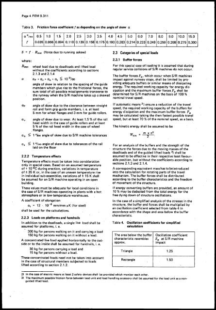
Page 4 <strong>FEM</strong> <strong>9.311</strong>Table 3. Friction force coefficient f as depending on the angle of skew 0:0: 0/00 0.5 1.0 1.5 2.0 2.5 3.0 3.5 4.0 4.5 5.0 6.0 7.0 8.0 9.0 10.0 15.0f 0.035 0.066 0.094 0.118 0.139 0.158 0.175 0.190 0.203 0.214 0.233 0.248 0.259 0.268 0.275 0.300S = f . R st8t(force due to running askew)2.3 Categories of special loadswhere:O:FO:vwheel load due to deadloads and lifted loadwithout the' coefficients according to sections2.1.3 and 2.1.4, ~oO:F + ~v + 0: 0 + O:s _' 10 looangle of skew in relation to the spacing of the guidemembers which give rise to the frictional forces, thesum total of all possible misalignments transverse tothe runway when the SiR machine takes up a skewedposition.angle of s~ew due to the clearance between straightrail and form grip guide members, i. e. at least5 mm for wheel flanges and 3 mm for guide rollers.angle of skew due to wear. At least 1.5 % of the railhead width in the case of guide rollers and at least5 % of the rail head width in the case of wheel" flanges.0: 0 ~ 1 °iot, angle of skew due to SIR machine tolerances2.3.1 Buffer forcesFor this special case of loading'it is assLimed that duringregular service collisions of SiR machines do not occur.The buffer forces Fp, which occur when SIR machinesimpact against runway stops, shall be limited by providingadequ!lte buffers or similar means of dissipatingenergy. The required working capacity for energy dissipationand the maximum,buffer forces Fp shall bedetermined for SIR machines on the basis of 100 %nominal travel speed., If automatic means 2) ensure a reduction of the travelspeed; the required working capacity of the buffers forenergy dissipation and the maximum buffer forces Fpmay be calculated taking the then fastest possible travelspeed, but at least 70 % of the nominal speed, as a basis.The kinetic energy shall be assumed to be'm x v2Wkin = 2O:s ~ 1 0/00 angle of skewdue to tolerances of the raillaid on the floor2.2.2 Temperature effectsTemperature effects must be taken into considerationonly in special cases. Based on an assumed temperatureof + 10 °C during erection, variations in temperatureof ± 35 K or, in the case of an uneven temperature risein individual sub-assemblies, variations of ±15 K shallbe assumed for an SIR machine operating in an openbuilding.These values must be adequate for local conditions inthe case of SiR machines operating in plants with a hotatmosphere or in low-temperature warehouses.A coefficient of elongationO:t = 12 ',10- 6 mm/mm xK (for steel)shall be used for the calculations.2.2.3 Loads on platforms and handrailsIn addition to the deadloads, a single live load shall beassumed for platforms, i. e.300 kg for persons walking on it and carrying a load150 kg for persons walking on it without a load.A concentrated live load applied horizontally to the outsideor to the inside shall be assumed for handrails, i. e.30 kg for persons carrying a load and15 kg for persons without a load.These concentrated loads need not be taken into accountin the case of structural members subjected to loadslifted according to section 2.1.2.For an analysis of the buffers and the strength of thestructure the forces due to the moving masses of thedeadloads and of the guided lifted loads 3) shall beassumed to be effective in their respective least favourableposition, but without the coefficients according tosections 2.1.3 and 2.1.4.'A corresponding equivalent mass has tobe introducedinto the calculation for rotating parts of the travelmechanism. The buffer forces shall be distributedaccording to the buffer characteristics and the freedomof movement of the structure.If energy converting buffers are provided, an amount of10 % may be deducted from the total energy for thefree dying down of structure oscillations.In the case of a simplified analysis of the stresses in thestructure,the' buffer end forces shall be multiplied byan oscillation coefficient selected from table 4 inaccordance with the shape and area below the buffercharacteristic.Table 4.Oscillation coefficients for simplifiedcalculationThe area below the buffer Oscillation coefficientcharacteristic resembles Sp at SiR machineapprox.impactTriangle 1.25Rectangle 1.50,2) In the case of electric means at least 2 safety devices shall' be provided which monitor each other.3) The maximum possible friction force between load unit and load handling accessory shall be assumed for the load unit as a nonguidedlifted load.


