FEM 9.311
FEM 9.311
FEM 9.311

You also want an ePaper? Increase the reach of your titles
YUMPU automatically turns print PDFs into web optimized ePapers that Google loves.
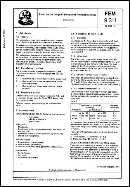
Rules for the Design of Storage and Retrieval MachinesStructures<strong>FEM</strong><strong>9.311</strong>02.1978 (E)1 . Calculation1.1 . GeneralThe calculations must be in compliance with acceptedrules of statics, dynamics, and theoretical mechanics.Provided that identical factors of safety are adhered to,the calculations may also be based on the results of testscarried out for determining the stresses which are producedin a structure under the assumed load conditions.The data concerning system, dimensions, and cross'sections shown in calculations and drawings must be inagreement. Discrepancies are not permissible unlessthese have the effect of increasing beyond any doubtthe safety of all components.1.2 Calculation methodFor the loads assumed as explained in section 2, thethree possible causes of failure are taken into accountas follows:ABCOverstraining of materials.beyond t~e elastic limitOverstraining of structures beyond the criticalbuckling stresses .Overstraining of materials i:leyond the fatiguestrength1.3 . Perm issible stressesDetails on the·permissible stresses concerning A, B, andC above can be seen from the future <strong>FEM</strong> design rulesfor crane structures.Relevant national standards apply for the transitionperiod.2 Assumed loadsStructures are subjected to the folloiNing load categories:main loads,additional loads andspecial loads.Main loads:- Deadloads,- lifted loads (lifting carriage deadweight and weight ofthe load unit),- horizontal forces of inertia produced by drive units,- statical stabilizing forces.Additional loads:Forces due to running askew,- effects due to temperature,- loads 'on walkways, stairs, platforms, and handrails.Special loads:- Buffer forces,- test loads,emergency catch loads.2.1· Categories cif main loads2.1.1 Dead loadsDeadloads are the forces due to the weight of all fixedand moving parts which are permanent operationalcomponents of the mechanical and electrical equipment,and of the proportionate share of the load supportingmeans such as-ropes but with the exception of the loadslisted in 2.1.2.2.1.2 Lifted loads. The lifted loads comprise the weight of the load unitand the deadweight of assemblies receiving the load unitsuch as telescopic load fork and roller table, the deadweightof the lifting carriage, and the proportionateshare of the weight of the load supporting means suchas ropes, chains, etc. '2.1.3 Effects of vertical forces of inertia .The effects of vertical forces of innertia produced whenmoving the lifting carriage and the loads listed i.n sections2.1.1 and 2.1.2 are taken into account by applying ...deadload coefficients" l{J and ,.I ifted load coefficients" 1/1.~.1.3.1 Deadload coefficients l{JThe deadloads of SiR machines in motion (see section2.1.1) a'nd the corresponding stress resultants or stressesshall be multiplied by a deadload coefficientl{J selectedfrom table 1. .Table 1Travel speed Ut in m/min DeadloadRunways 1 coefficientwith joints without joints l{Jup to 63 up to 100 1.1above 63 to 125 above 100 to 200 1.2above 125 above 200 ' 1.3In the case of live loads on a SiR machine running onspring·loaded, plastic, etc. wheels l{J = 1.1 may be used forcalculation independent of the travel speed and the typeof runway.Taking an SiR machine on steel rim travel wheels as anexample:a) Travel speed Ut = 125 m/min, l{J = 1.2b) Travel speed Ut = 50 m/min, l{J = 1.12.1.3.2 Lifted load coefficient 1/1 and lift,ing classesThe lifted loads according to section 2.1.2 or the stressresultants or the corresponding stresses must be multipliedby a lifted-load coefficient 1/1 accord)ng to table 2.Its value depends on the su rge to be expected from theload lifting means when lifting starts and thus on thenominal lifting speed UH; it is the smaller the moreflexible hoist unit and structure and the lower and more'Federation Europeenne de la ManutentionContinued on pages 2 to 5COP,yright by <strong>FEM</strong> Section IX. Available in English (El, French (F), German ([)l, Italian (I); sources of supply see back page.
Page 2 <strong>FEM</strong> <strong>9.311</strong>constant acceleration and deceleration are when thevertical motion is reversed.The SiR machines are therefore classified into liftingclasses H 1, H2, and H3, each of wh ich has a differentload coefficient I/J assigned to it according to table 2.Table 2The integration constants c, and C2 are determinedfrom the initial conditions:. aY(O) = 0 c, x 0 + c2 - w 2y(O)o = w xc, - C2 X 0 c, oThus, the oscillation equation is:Lifting Lifted load coefficient I/J Average main hoistclass for a lifting speed VH .' accelerationo x sin w t + ~ x cos w t - JL.of up to 90 mlmin ± am in m/s 2 w 2 w 2H1H2H31.1 + 0.0022 x VH1.2 + 0.0044 x VH1.3 + 0.0066 x VH~ 0.6~ 1.3> 1.3') Y(t)1) ±am 1.3 m/s 2 max. if persons ride on the iifting carriageduring vertical motions2.1.4 Horizontal forces of inertia producedby driveunits .2.1.4.1 Dynamic oscillation coefficientThe forces of inertia affecting the structure of an SIRmachine due to acceleration and deceleration of motionssuch as horizontal travel, lifting, and telescoping shallbe determined on the basis of the maximum forces producedby the respective drive units in regular service. Tosimplify the calculation for taking into account thedynamic effects, the "quasistatic" forces affecting thestructure may be multiplied by the coefficient Sw, the"quasistatic" forces being those which result when con,sidering the system's centre-of-mass motion under the.effects of the drive forces, of the resistances to motion .and of the forces of inertia. Application of the coefficientSw is subject to the condition that the driving forces acton the SiR m~chine practically without any play.For dimensioning the SiR machines it is necessary toknow exactly the stresses due to oscillations caused bytravel motions. Deflections, stresses, and stress resultansshall be multiplied by the dynamic oscillationcoefficient Sw'Y(t) = ~ x(coswt-1) orw 2 l!LX.Jl x (cos w t - 1)cdynamicdeformationstaticdeformation xoscillationcoefficient Swwhere:m dynamic equivalent mass of the flexible massesc spring constant of the structurea mean deceleration (acceleration) of thehorizontal motion.sa - braking pat~ (path of acceleration)t a period of deceleration (period of acceleration)Ytt) dynamic deformationFigure 2.+2+1Oscillation coefficient Swcos w t - 1(5)(4)Figure 1.Dynamic equivalent systemle'm/s 2aIt- ta SOmcSa(1) maximum amplitude of oscillation during deceleration(-) Sw max(2) "quasistatic" mean position during deceleration(3) position of rest(4) "quasistatic" mean position during acceleration(5) maximum amplitude of oscillation during aceleration. (+)mji+c xy+m x a = 0y + L Y + a = 0mY + w 2 X y.+ a = 0y + w 2 xy .= -aThe integral function of the above differential equationis:aY(t) c, x·sin w t + C2 X cos w t - w 2w 2 = ~ mAssumptions:damping is ignoredconstant deceleration (or acceleration)ta > Ta(Ta = natural oscillating period of the structure)The oscillation functionY(t) = m C X a x (cos w t - 1)reaches its maximum if the expression (cos w t· - 1)assumes the value (-2).
Since the stresses to which the structure is subjected aredirectly proportional to the dynamic deformations, theoscillation coefficient Swmax = 2 must be used forfurther calculations of deformations, stresses, and stress. resultants.2.1.4.2 Effect of horizontal forces of inertiaWithout the coefficients l{) and t/J according to section2,1.3 but with the oscillation coefficient according tosection 2.1.4.1, the dynamic effects of the masses resultingfrom structure flexibility shall be assumed to beappl ied to the individual centres of gravity (5, • 52. 53.etc.).Example':F, horizontal dynamic force of acceleration due to theload unit and the weight of the lifting carriageF 2F 3horizontal force of dynamic acceleration due to thedistributed load of the masthorizontal force of dynamic acceleration due to theweight of bottom carriage, travel mechanism andattachments (e. g. control cubicle, hoist mechanism,etc.)The masses shall: be considered according to their distributionin each particular case.Figure 3.-.F1/VlA\~-"-----'R min = R statF,xh,+ F 2 xh 2 + F 3 xh 3r<strong>FEM</strong> <strong>9.311</strong> Page 3For SIR machines, the stability is defined as follows:Stability:v =L stabilising momentSL overturning momentsR.tatx rThe stability v shall be ~ 1.5 under service conditions;in exceptional situations, e. g. for emergency braking, itshall be at least 1.1 (leaving the safety claws out of consideration).For SiR machines which are positively prevented fromtilting (e. g. by positively guided travel wheels), thestability analysis is omitted if· the negative wheel loads. are completely absorbed by the guiding members andtransmitted to the rack or building structure.2.1.4.3 Friction force coefficient Ji.,The driving forces on the travel wheel periphery arelimited by the friction coefficient applicable to thetravel wheel/rail pair. .The driving force which can be continuously transmittedis thus ~ R min x J.L. For steeH~n-steel pairs,J.L = 0.2 shall be used as a maximum...'N.r:::.F2t-S22.1.4.4 Lateral forces SzIf, due to forces of inertia, lateral forces occur transverselyto the runway centre line, these shall be transmittedto the rails by form and friction grip in linewith the.guiding members and the systems of thestructure and travel mechanism.rn I, F 3s~.r:::.I't-.IRlDepending on the direction of acceleration, the dynamicforces of inertia tend to increase or to decrease the wheelloads R, and R 2 .F, = (mL + mH) x 2 x am,F 2where:,mLmHmsmemAam=. m. x 2 x ·a m •F 3 = (me + mAl x am,mass of the load unitmass of the lifting carriagemass of the mastmass of bottom carriagemass of the attachments to the bottom carriagemean accelerationrsince Swsince Swsince SwR2221 (unsprung)2.2 Categories of additional loads2.2.1 Forces due to running askewDepending on the systems of travel mechanism andstructure, form grip forces are produced which acton the guiding members (wheel flanges or guide rollers)of an SIR machine by running' askew at an angle a,and from these frictional rubbing forces result whichact on the contact surfaces of the travel wheels.For the generally accepted tolerances of travel wheeldiameter, parallelism of the wheel bore axes and runwayalignment, a linear law of friction forces appliesto the longitudinal and transverse slip of two travelwheels of ferrous material on a steel rail:where:f = 0.30 x (1 _ e- O ,25x a)e = base of the natural logarithms 2.71828a = angle of skew in 0/00
Page 4 <strong>FEM</strong> <strong>9.311</strong>Table 3. Friction force coefficient f as depending on the angle of skew 0:0: 0/00 0.5 1.0 1.5 2.0 2.5 3.0 3.5 4.0 4.5 5.0 6.0 7.0 8.0 9.0 10.0 15.0f 0.035 0.066 0.094 0.118 0.139 0.158 0.175 0.190 0.203 0.214 0.233 0.248 0.259 0.268 0.275 0.300S = f . R st8t(force due to running askew)2.3 Categories of special loadswhere:O:FO:vwheel load due to deadloads and lifted loadwithout the' coefficients according to sections2.1.3 and 2.1.4, ~oO:F + ~v + 0: 0 + O:s _' 10 looangle of skew in relation to the spacing of the guidemembers which give rise to the frictional forces, thesum total of all possible misalignments transverse tothe runway when the SiR machine takes up a skewedposition.angle of s~ew due to the clearance between straightrail and form grip guide members, i. e. at least5 mm for wheel flanges and 3 mm for guide rollers.angle of skew due to wear. At least 1.5 % of the railhead width in the case of guide rollers and at least5 % of the rail head width in the case of wheel" flanges.0: 0 ~ 1 °iot, angle of skew due to SIR machine tolerances2.3.1 Buffer forcesFor this special case of loading'it is assLimed that duringregular service collisions of SiR machines do not occur.The buffer forces Fp, which occur when SIR machinesimpact against runway stops, shall be limited by providingadequ!lte buffers or similar means of dissipatingenergy. The required working capacity for energy dissipationand the maximum,buffer forces Fp shall bedetermined for SIR machines on the basis of 100 %nominal travel speed., If automatic means 2) ensure a reduction of the travelspeed; the required working capacity of the buffers forenergy dissipation and the maximum buffer forces Fpmay be calculated taking the then fastest possible travelspeed, but at least 70 % of the nominal speed, as a basis.The kinetic energy shall be assumed to be'm x v2Wkin = 2O:s ~ 1 0/00 angle of skewdue to tolerances of the raillaid on the floor2.2.2 Temperature effectsTemperature effects must be taken into considerationonly in special cases. Based on an assumed temperatureof + 10 °C during erection, variations in temperatureof ± 35 K or, in the case of an uneven temperature risein individual sub-assemblies, variations of ±15 K shallbe assumed for an SIR machine operating in an openbuilding.These values must be adequate for local conditions inthe case of SiR machines operating in plants with a hotatmosphere or in low-temperature warehouses.A coefficient of elongationO:t = 12 ',10- 6 mm/mm xK (for steel)shall be used for the calculations.2.2.3 Loads on platforms and handrailsIn addition to the deadloads, a single live load shall beassumed for platforms, i. e.300 kg for persons walking on it and carrying a load150 kg for persons walking on it without a load.A concentrated live load applied horizontally to the outsideor to the inside shall be assumed for handrails, i. e.30 kg for persons carrying a load and15 kg for persons without a load.These concentrated loads need not be taken into accountin the case of structural members subjected to loadslifted according to section 2.1.2.For an analysis of the buffers and the strength of thestructure the forces due to the moving masses of thedeadloads and of the guided lifted loads 3) shall beassumed to be effective in their respective least favourableposition, but without the coefficients according tosections 2.1.3 and 2.1.4.'A corresponding equivalent mass has tobe introducedinto the calculation for rotating parts of the travelmechanism. The buffer forces shall be distributedaccording to the buffer characteristics and the freedomof movement of the structure.If energy converting buffers are provided, an amount of10 % may be deducted from the total energy for thefree dying down of structure oscillations.In the case of a simplified analysis of the stresses in thestructure,the' buffer end forces shall be multiplied byan oscillation coefficient selected from table 4 inaccordance with the shape and area below the buffercharacteristic.Table 4.Oscillation coefficients for simplifiedcalculationThe area below the buffer Oscillation coefficientcharacteristic resembles Sp at SiR machineapprox.impactTriangle 1.25Rectangle 1.50,2) In the case of electric means at least 2 safety devices shall' be provided which monitor each other.3) The maximum possible friction force between load unit and load handling accessory shall be assumed for the load unit as a nonguidedlifted load.
<strong>FEM</strong> <strong>9.311</strong> Page 5The travel wheels of SiR machines with or without apayload shall not lift off the rail due to the 110 % bufferforce and the above-mentioned deadloads and liftedloads. Reaction pressure rollers or safety claws shall beprovided as required for absorbing negative wheel loads.The buffer stops shall be dimensioned for absorbing atleast the actual buffer end force Sp.2.3.2 Test loads2.3.2.1 General function testThe functions of load pick-up, lifting, lowering, andtravelling of SIR machines are tested by applying thefollowing load:'test load: P k = 1.25 payloadFor the analysis of stresses (overstraining beyond theelastic limit) and of stability the test load P k shall bemultiplied by the reduced lifted load coefficient!...±..Jk.',I,' ='I' 2', The assumed load makes it necessary to proceed asfollows for applying the test load:With the test load applied, all motions shall be individuallytested with reasonable care and with the'load in theleast favourable positions. A motion may not beinitiated before the oscillations caused by the previousmotion' have died down.2.3.3 Emergency catch loads2.3.3.1 Function teSt of the catching deviceOn SiR machines equipped with a speed controlledcatching device, the function test of this device iscarried out by applying the catch load P k = 1.25 . payload.'The catch load shall, be positioned centrally on the loadpick-up device.'The following tests shall be carried out:1) function test of the overspeed governor by loweringthe lifting carriage at excessive speed or by asimulation of this condition;2) 'function test of the catching device by manuallocking of the overspeed,governor during the loweringmotion;3) free-fall stop test of the lifting carriage lifted uptogethe~ with the catch load.The free-fall stop' test according to 3) above can beomitted if the catching device is built up of functiontestedcomponents for which an official certificate hasbeen issued.For the stress analyses according to section 1.2 A "Overstrainingof materials beyond the elastic limit"and B;,Overstrainingof structures beyond the critical bucklingstresses" the catch load shall be multiplied by the increasedlifted load coefficient t/J ".For specifying the increased lifted load values I/J" it hasbeen taken into account that the actual speed for trippingthe catching device v ab considerably exceeds the nominallifting speed VH' which is espressed by the followingequation:: .Vab= -J v g 2 + 2xgxSR + 2xgxSFwhere:Vg preset trip,ping speed of the overspeed governor~ 1.4 x VHSRspacing of the notches of the overspeed governoorin relation to the vertical path of the lifting carriageSF idle path of the catching mechanism until brakingstartsg 9.81 m/s 2The energy equation indicates the mean decelerationduring the catching operation:where:m XV~b22 + m x g x h --'- m x am x h = 0hence:am mean deceleration Ih catching or braking path of the lifting carriagem mass of the test load and of the lifting carriagedead ' weightThe maximum deceleration amax in the event ofcatching results from the characteristic curve of the'working diagram for the catching device and by takinginto account an oscillation coefficient according totable 4.Table 5.2 x am triangular diagramamax ' 1.75 x am trapezoidal diagrljm1.5 x am rectangular diagramThe increased lifted load coefficient I/J" results from therelationship between the maximum deceleration due tobraking and acceleration due to gravity.I/J" =a;axIf an exact calculation of the increased lifted loadcoefficient is omitted, the calculation may be simplifiedby taking I/J" from table 6.Table 6.Approximate figures for I/J"Increased Iifted loadcoefficient I/J" 4)Lifting speed VH (m/min)for catcning approx. work- ~20 ~31.5 ~50 >50by ingdiagram 'Clampingrollercatchingtriangular 5 6 - -deviceBrake typecatching trapezoidal 2.5 3 3.5 -deviceCushioningcatching rectangular 2, 2 2 2device41 The above values for I/J" can be influenced by varying thedesign of the catching device (angle of the sloping surfacein the catching block, width and diameter of the catchingroller)Depending on particular applications, additional calcula;tlons regarding oscillation dynamics may be advisable if dueto its flexibility the structure is definitely capable of absorbinga certain part of the energy produced by catching.
Erstellt durch den technischen UnterausschuB •• Regal bed iengeriite und Stapelkrane" der Sektion IX der }Prepared by the Technical Sub-Committee "Storage and Retrieval Machines and Stacker Cranes" ofSection IX of theEtabli par le sous-comit6 technique ..Transtockeurs et 1Xlnts gerbeurs" de la section IX de laEmesso della sottocommissione tecnica ..Trasloelevatori e gruSekretariat:Secretariat:Secr6tariat:Segretariato:Sekretariat der <strong>FEM</strong> Sektion IXcIa VOMAFachgemeinschaft FordertechnikPostfach 71 01 090-6000 Frankfurt 71F6d6ration Europ6ennede la Manutention(<strong>FEM</strong>) ,impilatrici'aella sezione IX della --_-::.-_-------Zu beziehen durch das oben angegebene Sekretariat oder durch die folgenden Nationalkomitees der <strong>FEM</strong>Available from the above secretariat oi from the following national committees of the <strong>FEM</strong>En vente auprAs du secr6tariat QU des comit6s nationaux suivants de la <strong>FEM</strong>Da richiedere attraverso il su citato segretariato 0 i comitati nazionali della <strong>FEM</strong>BelgiqueComite National Beige de la <strong>FEM</strong>FabrimetalRue des Drapiers 21B-1050 BruxellesDanmark-Dansk National Komite <strong>FEM</strong>Transportmaterial ForeningenLille Kirkestraede 3DK - 1072 Kopenhagen KDeutschlandDeutsches Nationalkomitee der <strong>FEM</strong>VDMA .Fachgemeinschaft FordertechnikPostfach 71 01 09D '- 6000 Frankfurt 71EspanaComite Nacional Espanolde la <strong>FEM</strong>Associaci6n Nacional de Ingenieros IndustrialesVia Layetana 39 (bajos)E - Barcelona 3FranceComite National Francais de la <strong>FEM</strong>SIMMA - Syndicat des industries de materielsde manutention10, avenue HocheF --;- 75 382 Paris cedex 08Great BritainBritish National Committee of <strong>FEM</strong>Messrs. Peat, Marwick, Mitchell & Co.7 Ludgate BroadwayGB - London EC 4V 6DXIrelandIrish National Committee of <strong>FEM</strong> ,Institute for Industrial Research and Standards (11 RS)Ballymun RoadIRL - Dublin 9ItaliaComitato Nazionale Italiano de la <strong>FEM</strong>Associazione Nazionale IndustriaMeccanica Varia et Affine (ANIMA)Piazza Diaz 2I - 20123 ·MilanoLuxembourgComite National Luxembourgeois de la <strong>FEM</strong> .Groupement des Constructeurs et Fondeursdu Grand-Duche' de LuxembourgRue Alcide de Gasperi 7Plateau de KirchbergBoite postale No. 1304L - LuxembourgNederland 'Nederlands National Comite bij de <strong>FEM</strong>GKT-Vereniging van Metaal industrleenPostbus 190NL - 2700 Ad ZoetermeerNorgeNorwegian <strong>FEM</strong> GroupsNorsk VerkstedsindustrisStandardiseringssentral NVSBox 7072 H 'N - Oslo 3PortugalCommissao Nacional Portuguesa da <strong>FEM</strong>CEMUL - Prof. Eng. L. O. FariaAvenida Ant6nio Jose de Almeida - I.S.T.P - 1000 LisboaSchweiz / Suisse / SvizzeraComite National Suisse de la <strong>FEM</strong>Verein Schweizerischer Masch inen-I ndustriellerKirchenweg 4CH - 8032 ZurichSuomiFinnish National Committee of <strong>FEM</strong>Federation of Finnish Metal and Engineering IndustriesEtelaranta 10'SF - 00130 Helsinki 13SverigeSwedish National Committee of <strong>FEM</strong>Materialhanteringsgruppen Inom Sveriges MekanforbundBox 5506S - 11 485, Stockholm