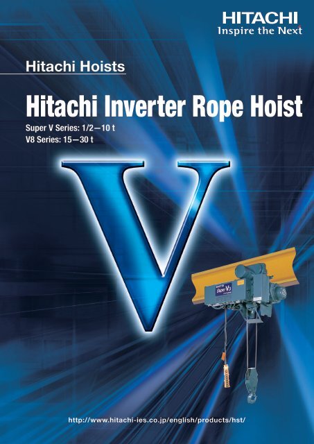
Hitachi Inverter Rope Hoist
Hitachi Inverter Rope Hoist
Hitachi Inverter Rope Hoist

Create successful ePaper yourself
Turn your PDF publications into a flip-book with our unique Google optimized e-Paper software.
<strong>Hitachi</strong> <strong>Hoist</strong>s<strong>Hitachi</strong> <strong>Inverter</strong> <strong>Rope</strong> <strong>Hoist</strong>Super V Series: 1/2-10 tV8 Series: 15-30 thttp://www.hitachi-ies.co.jp/english/products/hst/
Further-evolved <strong>Inverter</strong> <strong>Hoist</strong> that Employs Further-enhancedElectronic Control TechnologiesThe <strong>Hitachi</strong> inverter hoist that made it possible to transport loads in a delicatemanner and even in precision operations has been revamped with <strong>Hitachi</strong>’soriginal inverter added. The external appearance is almost no different from astandard hoist, but the new inverter hoist can be used in a wider range ofapplications. In addition, it can be used in a wider range of environments,because it is rainproof. The new hoist meets a variety of operation needs withthe further-enhanced electronic control technologies as well as the proven andhighly-valued functions inherited from previous products including the steplesscontrol (from Speed 1 to Speed 1/10) of the hoisting and lowering and thelongitudinal and traversing, the high-speed operation function for no-loadoperations, the function to reduce the impacts during the hoisting off andlowering onto the floor of the load, and the high positioning accuracy.Super V Series<strong>Hoist</strong>ing and lowering speeds:150% of the rated speed [in no-load operations]From Speed 1 to Speed 1/10Traversing speed:From Speed 1 to Speed 1/10Traveling speed:From Speed 1 to Speed 1/10V8 SeriesAdvantages<strong>Hoist</strong>s are being widely used as transport cranes. One of their characteristics is that they are being started and stoppedfrequently. <strong>Inverter</strong>-based control of hoists allows the service lives of expendable (mechanical) parts to be prolonged andthe starting current to be reduced.AdvantageHigh-speed operation that helpsreduce power consumptionWhen bringing or returning the crane (in no-load operations), theoperation time can be shortened by using the high-speed no-loadhoisting function and the high-speed traveling function (twice therated speed). In addition, the function that allows the crane to bestarted and stopped with reduced impacts reduces the startingcurrent.Power consumption(index)100100Commercial operation73<strong>Inverter</strong>-based operation27reductionReduction in power consumption that is achieved when a 3t inverter hoist is operated with cycles of 5 times per hourwith the hoist installed on a crane with a hoisting lift of 6m, a span of 12m and a 50m runway.3Advantages4Features of Super Vof standard6Tablespecifications8Dimensions anddimensions table forSuper VAdvantageService lives of expendable partscan be prolonged.The smooth operation reduces impacts on mechanical parts. Thisprolongs the times between replacements of parts, thereby reducingthe amount of waste.Service life index(times)2.02.01.0 1.01.01.2Fixed speedVariable speed(inverter)16Features of and Dimensionsand dimensions table forV818Brake liningWire ropeInstallation ofinverter hoists(Data from tests conducted by us)20AdvantageLeaves more space available for useThrough our efforts to make the control section etc. smaller, wesucceeded in making the hoist lighter and more compact than ourprevious products. This means that the new hoist leaves more spaceavailable for use.(65mm shorter and 5kg lighter than the previous product (3t standardheadroom type))New hoistPrevious productMore space isleft available foruse.Notes on wiring /About supply of power22<strong>Inverter</strong> units forsaddlesThe hoist is a product designed for transporting cargoes.It is not designed for lifting or transporting human beings.23
Super V Series and V8 SeriesEase of use and reliability has been further improved with the provenand highly-valued functions inherited from previous products.Features<strong>Inverter</strong>-based operationThe pendant’s push buttons provide high operabilityMinute changes in the position of the hoist can be made easily, andthe user can perform the inching operation in a smooth manner.Overloading prevention function is provided asa standard function.When hoisting is attempted of a load that is heavier than the capacity,the winding will be stopped automatically.Note: The overloading detection threshold may vary between 100 and 150% of the capacitydepending on the operation frequency, source voltage and motor temperature.Improved environmental resistanceBecause the inverter section is housed in the control panel, the hoist canbe used in environments that are on a par with operating environments forstandard hoists.High-speed operation (hoisting and lowering)function for no-load operationsWhen the hoist is operated with no load, high-speed operation at 150% ofthe rated speed will automatically be selected.Note 1: The no-load state detection threshold may vary between 0 and 25% of the capacity dependingon the source voltage, motor characteristics and temperature.Note 2: Certain special high hoisting lift hoists cannot be fitted with the high-speed operationfunction for no-load operations. Please contact us for details.Note 3: The high-speed operation function for no-load operations cannot be used in co-hoistingoperations. Please contact us for details.Electronic limit switch function(upper and lower limits)This function detects the hook position to allow hoisting and lowering tobe stopped automatically with reduced impacts (The user can easily setthe upper and lower limits according to his needs. The upper and lowerlimits are not set at the factory before shipment).Convenient information that makes for maintenanceInformation that is useful for maintenance, such as the number of times ofstarting, cumulative operation hours, when to replace the capacitor andinformation on abnormal conditions that have occurred, is displayed. Table of Standard <strong>Hoist</strong> TypesSuper V Series (inverter-based control of hoisting and traversing, inverter-based control of hoisting only)TypeStandard HeadroomType (P8-P11)Low HeadroomType (P12-P13)Double-Rail Type(P14-P15) Explanation of the product codesProducts equipped with a trolleyCapacity (t)<strong>Hoist</strong>ing lift<strong>Hoist</strong> typeTrolley typeSpecification<strong>Hoist</strong>inglift<strong>Hoist</strong>inglift<strong>Hoist</strong>inglift1/2t 1t 2t 2.8t 3t 5t 7.5t 10t6m 12m 6m 12m 6m 12m 6m 12m 6m 12m6m 6m 12m 6m 12m 6m 12m 6m 12m−−V8 Series (inverter-based control of hoisting and traversing)TypeStandard HeadroomType (P16-P17)Double-Rail Type(P16-P17)Specification<strong>Hoist</strong>inglift<strong>Hoist</strong>inglift15t8m 12m8m 12mFor information on types other than the ones listed above, please contact us.Control methodimproved No.20 H D T 8 W 320 H M V8 8 3Control methodTrolley improved No.<strong>Hoist</strong> improved No.Capacity12m 6m 12m 6m 12mCapacity20t12m12m<strong>Hoist</strong> section (catenary type)Capacity (t)<strong>Hoist</strong>ing lift<strong>Hoist</strong> type<strong>Hoist</strong> improved No.8m 12m6m 11m8m 12m8m 12m−8m 12m30t−12mControl method improved No.Control method8m 12m−8m 12m4Features of Super VPushbutton with 2 depressed positions for changing speed(on products equipped with a pendant with pushbuttons)The first and second depressed positions correspond to the low and highspeed settings, respectively. The low and high speed settings areindependent of each other and can be set to any desired speed.Vibration of the load during hoisting is very small.The vibration of the load during hoisting is very small because the startingand stopping impact reduction function reduces the impacts at startingand stopping. This function reduces the impacts on the building and cranegirder as well.Smooth traveling that minimizes the pendular motionof the load during travelingThe smooth acceleration and deceleration minimizes the pendular motionof the suspended load during traveling.The contactless main circuit provides high reliability.The main circuit is of a highly-reliable design that does not use any contactorin the entire main circuit from the inverter power supply to the motor.Reduced impacts on mechanical partsBecause the brake is applied when the motor rotation speed is low, theabrasion of the lining is reduced and so are the impacts on mechanicalparts such as the wire ropes, sieves, couplings and gears, which meansthat the service lives of these parts can be prolonged.Abnormal condition detection function that protectsthe hoist (for hoisting and lowering only)When an abnormal condition is detected (through comparison of theoperation command with the actual operation performed), the circuit willbe disconnected and the brake will be applied.CapacityRated loadindicated bytons. Example<strong>Hoist</strong>ing liftNo letter:low hoisting liftH:high hoisting lift<strong>Hoist</strong>Super V Series (10t or less)<strong>Inverter</strong>-based control of hoisting and traversing,By typeM : Standard Headroom TypeL : Low Headroom TypeD : Double-Rail Typependant-based operation 2.8HD-T55-W3<strong>Inverter</strong>-based control of hoisting only, pendant-basedoperation 2.8HD-T55-V3TrolleyT: electrically-drivenSuper V SeriesV8 SeriesControl methodW : inverter-based control of hoisting and traversingV : inverter-based control of hoisting onlyW : dual-speed typeV : dual-speed type (during independent operation of the hoist)V8 Series (15t or more)<strong>Inverter</strong>-based control of hoisting and traversing,pendant-based operation, dual-speed 20HD-T88-W3In the V8 Series, there is no product with inverter-based control of hoisting only.45
Super V Series and V8 Series6Super V SeriesV8 Series<strong>Hoist</strong>ingTraversing<strong>Hoist</strong>ing lift<strong>Inverter</strong>-basedcontrol of hoistingTraversingWire rope<strong>Hoist</strong>ing liftWire rope<strong>Inverter</strong>basedCommercialMotorMotorCapacity t 15<strong>Hoist</strong> load t 15.2Standard Low hoisting lift8mHeadroom Type High hoisting lift12Double-Rail TypeLow hoisting lift 8mHigh hoisting lift12m/s0.01−0.100.15Speed 2m/min0.6− 6.0 9.0Output kW162 The figures in [ ] are the no-load operation speeds.Capacity t 1/2 1 2 2.8 3 5 7.5 10<strong>Hoist</strong> load t 0.51 1.01 2.02 2.83 3.03 5.07 7.65 10.2Standard Headroom TypeLow hoisting lift66 6 6 6 8 8 8mHigh hoisting lift1212 12 12 12 12 12 12Low Headroom TypeLow hoisting lift 6 6 6 6 6 6 − −mHigh hoisting lift − 12 12 12 12 11 − −Double-Rail TypeLow hoisting lift − − − 6 6 8 8 8mHigh hoisting lift− − 12 12 12 12 12 12m/s0.022− 0.217 0.3250.022−0.217 0.325 0.017−0.167 0.25 0.015− 0.15 0.225 0.015−0.15 0.225 0.013−0.133 0.2 0.012−0.12 0.18 0.01−0.100.15Speed 1m/min1.3− 13 19.51.3−13 19.5 1.0−10 15 0.9− 9.0 13.5 0.9− 9.0 13.5 0.8−8.0 12 0.72−7.2 10.8 0.6−6.0 9.0Motor outputkW1.2 2.3 3.5 4.8 5.0 7.0 9.5 10.5No. of poles of the motor 4 4 4 4 4 4 4 4Speedm/s0.042− 0.417 0.042−0.417 0.042−0.417 0.042−0.417 0.042−0.417 0.042−0.417 0.028− 0.283 0.028−0.283m/min 2.5−25 2.5−25 2.5−25 2.5− 25 2.5−25 2.5−25 1.7−17 1.7− 17Standard Headroom TypeMotorLow Headroom TypeoutputDouble-Rail TypeSpeedStandardHeadroom TypeLowHeadroom TypeDouble-Rail TypeMotoroutputNo. of poles of the motorStandard Headroom TypeLow Headroom TypeDouble-Rail Type1 The figures in [ ] are the no-load operation speeds.Table of standard specificationsCommon to50 and 60Hz50Hz60Hz50Hz60Hz50Hz60Hz50Hz60HzTable of standard specificationskW0.36 0.36 0.36 0.55 0.55 0.75 0.56×2 0.56×20.36 0.36 0.36 0.55 0.55 0.75 − −− − 0.36 0.55 0.55 0.55 0.55×2 0.55×2m/s 0.35 0.35 0.35 0.35 0.35 0.35 0.233 0.233m/min 21 21 21 21 21 21 14 14m/s 0.417 0.417 0.417 0.417 0.417 0.417 0.283 0.283m/min 25 25 25 25 25 25 17 17kW0.30 0.30 0.30 0.45 0.45 0.63 0.47×2 0.47×20.36 0.36 0.36 0.55 0.55 0.75 0.56×2 0.56×20.30 0.30 0.30 0.45 0.45 0.63 − −0.36 0.36 0.36 0.55 0.55 0.75 − −− − 0.30 0.45 0.45 0.45 0.45×2 0.45×2− − 0.36 0.55 0.55 0.55 0.55×2 0.55×2Standard Headroom Type 4 4 4 4 4 4 6 6Low Headroom Type4 4 4 4 4 4 − −Double-Rail Type − − 4 4 4 4 4 4No. of strands22 2 2 2 4 4 4Composition6×W (19)-B6×Fi (29)-B 6×Fi (29)-B 6×Fi (29)-B 6×Fi (29)-B 6×Fi (29)-B 6×Fi (29)-B 6×Fi (29)-BDiameter mm 6.3 8 11.2 14 14 12.5 14 16No. of strands44 4 4 4 4 − −Composition6×W (19)-B6×W (19)-B 6×Fi (29)-B 6×Fi (29)-B 6×Fi (29)-B 6×Fi (29)-B − −Diameter mm 4 6.3 8 10 10 12.5 − −No. of strands −− 4 4 4 4 4 4Composition −− 6×Fi (29)-B 6×Fi (29)-B 6×Fi (29)-B 6×Fi (29)-B 6×Fi (29)-B 6×Fi (29)-BDiameter mm − − 8 10 10 12.5 14 160.5− 5.0 7.50.33−3.3 5.01818No. of poles 4 4 4Speedm/s 0.028− 0.2830.028−0.2830.028−0.283m/min 1.7−171.7−171.7−17OutputkW 0.55×20.55×20.84×2No. of poles 4 4 4Number of strands44−Standard HeadroomTypeComposition6×Fi (29)-B6×Fi (29)-B −Diameter mm2022.4 −Number of strands448Double-Rail Type Composition6×Fi (29)-B6×Fi (29)-B6×Fi (29)-BDiameter mm2022.4202020.3−12−120.008− 0.083 0.1253030.4−−−120.006−0.055 0.083Standard specificationsOperation methodPower supplyProtection structureStandard productOperation voltageFrequency of starting<strong>Hoist</strong>ingRepetitive ratingDuty factor(rate of loading 0.63)Frequency of startingTraversingDuty factorPower supply methodThree-phase 200V 50/60Hz 380V 50Hz 440V 60Hz220V 60Hz400V 50/60HzPushbuttons on the pendant Eight pushbuttons designed to be operated by an operator standing on the floor (on, off, up, down, east, west, south and north)The pushbuttons with 2 depressed positions are as follows:<strong>Inverter</strong>-based control of hoisting and traversing : up, down, east, west, south and north<strong>Inverter</strong>-based control of hoisting only : up and down<strong>Inverter</strong>-based control of traversing only : east and west200VAC or 220VAC400 times per hour40%ED400 times per hour40%EDPower is supplied via cable. (In the case where a contact type current collector such as a collector/bus duct is used, please make sure that a double-trolley system is used.)JIS C0920 IP44In the case of outdoor use, please provide a covered refuge bay so that the hoist is not exposed to rain.The IP rating is for the motor section and the control panel.−10 to +40 ˚C (without freezing)90% or less (without condensation)Ambient temperatureHumidityPaint color Munsell 2.5B, 2.5/1Compliance with standardsJIS C9620 (Electric <strong>Hoist</strong>s), a crane structure standardSafety instructions for using the productStandard specification products cannot be used in special environments such as the ones listedbelow. Please contact us if you need a product that can be used in such environments.(1) Acid, alkali and saline atmospheres and corrosive gas atmospheres(2) Environments with an ambient temperature higher than 40 ˚C(3) Dusty environments(4) Environments in which the product is subjected to water splashes(5) Environments with a risk of ignited explosion such as environments in which volatile dust oran organic solvent exists(6) Environments in which the product is used very frequentlyFor the use of the product in a place with significant power supply noises, we recommend that anoise filter be installed, because such noises can cause malfunctioning such as a sudden stop.An inverter hoist will not stop immediately after the OFF pushbutton is pressed. The function to start and stop the hoistwith reduced impacts requires a deceleration distance that is proportional to the operating speed. Therefore, be sure tooperate the hoist taking into account the deceleration distance. In particular, please allow for a sufficient decelerationdistance when you operate the hoist at a high speed above the rated speed with the hoist carrying no load.If the hoist is operated continuously for more than 1 minute at the lowest speed, the inverter’ s overheatingprotection function may be activated to stop the hoist. In that event, please leave the hoist stopped until theinverter cools down (usually 5 minutes or more) before restarting the hoist.The inverter hoist requires a time period of about 4 seconds before it becomes capable of operating after theON pushbutton is pressed. Do not press any pushbutton during this period.7of standard6Tablespecifications
Standard Headroom Type <strong>Hoist</strong>s<strong>Inverter</strong>-based control of hoistingSuper V SeriesDimensions1/2t-1t2t-3t Dimensions5t7.5t, 10t Table of dimensionsCapacityOperation that usesan 8-pushbuttonpendantApprox. dimensions(mm)Type<strong>Hoist</strong> typeTrolley typeMin. curve radiusDimensions with respect to I-beam(150×75×5.5)200×100×7250×125×7.5300×150×11.5450×175×11Approx. weight(t)LHABMEWKJdPa(m)(mm)(kg)1/2M-T65-V31/2M6-V3F3613743871/2T56,0005205002080Upper limitLower limit385190200/2901/2HM-T65-V31/2HM6-V31/2T51001054096211.35.0S1742670.5740T14714815112,000660530175 185U53/4352/4249/391M-T65-V3F374387400 1M6-V31T56,00054547520858 pushbuttons(in the case of operationthat uses an 8-pushbuttonpendant designed foruse by an operatorstanding on the floor)400255200/290S42679217904596231.5T1HM-T65-V31HM6-V31481511601: Dimension W indicates (drive side / driven side).2: Dimension U indicates (low hoisting lift /high hoisting lift).3: Unless otherwise specified by the customer, a product compatible with I-beams with the dimensions shown in the colored columns will be delivered.4: As the product contains electronic components, be sure to install a buffering mechanism or buffering material on the stoppers for the longitudinal and traversing.5: When a 1/2t hoist is used on I-beams with the dimensions “150 x 75 x 5.5,” the min. curve radius shall be 5m.6: In the case where a 1/2t hoist is used on I-beams with the dimensions “150 x 75 x 5.5,” a 50mm filler must be installed between the I-beams and the building.1T512,00071551090115200 220U47/4244/3935/302M-T75-V3F3783914048 pushbuttons(in the case of operationthat uses an 8-pushbuttonpendant designed foruse by an operatorstanding on the floor)2M7-V32T56,0006204353075450220200/290S42679229855696361.8T2HM-T75-V32HM7-V31481511602T512,000640615110100295 345U4239302.8M-T65-V32.8M6-V3F4174304433580S5277102Upper limitLower limit2.8HM-T65-V371128422.0T2.8HM6-V33T5 3T52.86,000 12,0001,115610 645510 660495245230/310177187185120110405 435U3828303M-T65-V3F4174304433M6-V33580S527710271128422.0T3HM-T65-V33HM6-V33T5 3T536,000 12,0001,115610 645510 660495245230/310177187185120110405 435U382830Table of dimensionsOperation that usesan 8-pushbuttonpendantCapacityApprox. dimensions(mm)Min. curve radiusDimensions with respect to I-beam300×150×11.5450×175×11600×190×13Approx. weightType<strong>Hoist</strong> typeTrolley type(t)LHABMEGWdPa(m)(mm)(kg)Upper limitLower limit5M-T55-V35M5-V35T58,00084569051,1908 pushbuttons(in the case of operationthat uses an 8-pushbuttonpendant designed foruse by an operatorstanding on the floor)5HM-T55-V35HM5-V35T512,000955800490305−250/33090156/140 (drive side / driven side)583.0F S T U450 77 225 30463 102 223 32Upper limitLower limit1: Dimension W indicates (drive side / driven side)(7.5t and 10t).2: Dimension U indicates (low hoisting lift /high hoisting lift).3: Unless otherwise specified by the customer, a product compatible with I-beams with the dimensions shown in the colored columns will be delivered.4: As the product contains electronic components, be sure to install a buffering mechanism or buffering material on the stoppers for the longitudinal and traversing.8 pushbuttons(in the case of operationthat uses an 8-pushbuttonpendant designed foruse by an operatorstanding on the floor)7.5M-T55-V37.5M5-V34FT57.5HM-T55-V37.5HM5-V34FT510M-T55-V310M5-V35FT510HM-T55-V310HM5-V35FT57.5108,00012,0008,00012,0001,3451,5151,0751,1501,0751,150830905885960560760650786315355640670230/310250/330100100128156/140 (drive side / driven side)6969Straight lineF S T U F S T U440 77 186 28 450 77 225 30453 102 184 30 460 102 225 30461 117 189 25 468 117 230 25710 775 9701,030 1,280 1,34010Dimensions anddimensions table forSuper V1011
Low Headroom Type <strong>Hoist</strong>s<strong>Inverter</strong>-based control of hoisting and traversing<strong>Inverter</strong>-based control of hoistingSuper V Series Dimensions1/2-1t (with a hoisting lift of 6m) 1t (with a hoisting lift of 12m) 2t-5t Dimensions1/2-1t (with a hoisting lift of 6m) 1t (with a hoisting lift of 12m) 2t-5tIn the case of a 2t hoist with a hoisting lift of 6mIn the case of a 2t hoist with a hoisting lift of 6m Upperlimit Upper limit Upperlimit Upperlimit Upper limit UpperlimitTable of dimensionsCapacityLower8 pushbuttonslimit(in the case of operationthat uses an 8-pushbuttonpendant designed foruse by an operatorstanding on the floor)Operation that usesan 8-pushbuttonpendantApprox. dimensions(mm)Type<strong>Hoist</strong> typeTrolley typeMin. curve radiusDimensions with respect to I-beam(150×75×5.5)200×100×7250×125×7.5300×150×11.5450×175×11Approx. weight(t)LHABWEFdJPa(m)(mm)(kg)G3613743871/2L-T55-W31/2L5-V31/2T5-V30.56,000400550560200/29045034040269621403.5 (5.0)S174267190T147148151U5352491L-T55-W3G3743874001L5-V31T5-V36,00042566553049536028542358 pushbuttons(in the case of operationthat uses an 8-pushbuttonpendant designed foruse by an operatorstanding on the floor)1HL-T55-W3 2L-T55-W3 2HL-T55-W3 2.8L-T55-W3 2.8HL-T55-W3 3L-T55-W3 3HL-T55-W3 5L-T55-W3 5HL-T55-W31200/290S4267924596233.51HL5-V31T5-V312,000450675560T14815116052546535108315U5249401: Dimension W indicates (drive side / driven side).2: Dimension U indicates (low hoisting lift /high hoisting lift).3: Unless otherwise specified by the customer, a product compatible with I-beams with the dimensions shown in the colored columns will be delivered.4: As the product contains electronic components, be sure to install a buffering mechanism or buffering material on the stoppers for the longitudinal and traversing.5: When a 1/2t hoist is used on I-beams with the dimensions “150 x 75 x 5.5,” the min. curve radius shall be 5m.6: In the case where a 1/2t hoist is used on I-beams with the dimensions “150 x 75 x 5.5,” a 50mm filler must be installed between the I-beams and the building.G3783914042L5-V32T5-V36,0005157056055254804285330Lowerlimit2200/290S4267925696364.52HL5-V32T5-V312,000520775635T14815116050556034104460U3229202.8L5-V33T5-V36,000600750620230/31056557546G4174301005.0S5277443 1024552.8HL5-V33HLT5-V32.812,000 650795700 230/410 605 66071 501284299Straight lineT U1771872818185 206208 pushbuttons(in the case of operationthat uses an 8-pushbuttonpendant designed foruse by an operatorstanding on the floor)3L5-V33T5-V36,000600750620230/31056557546G4174301005.0S5277443 1024553HL5-V3Lowerlimit3HLT5-V3312,000 650795700 230/410 605 66071 501284299Straight lineT U1771872818185 206205L5-V335450 77463 1027655HL5-V35T5-V3 5T5-V356,000 11,000810845 955690 800250/3306356759035156/140(drive side / driven side)5889Straight lineGSTU225 23223 258358 pushbuttons(in the case of operationthat uses an 8-pushbuttonpendant designed foruse by an operatorstanding on the floor)LowerlimitTable of dimensionsOperation that usesan 8-pushbuttonpendantCapacityApprox. dimensions(mm)Type<strong>Hoist</strong> typeTrolley typeMin. curve radiusDimensions with respect to I-beam(150×75×5.5)200×100×7250×125×7.5300×150×11.5450×175×11Approx. weight(t)LHABWEFdJPa(m)(mm)(kg)G3613743871/2L-T55-V31/2L5-V31/2T50.56,000400550560200/29045034040269621401.3 (5.0)S174267190T147148151U5352498 pushbuttons(in the case of operationthat uses an 8-pushbuttonpendant designed foruse by an operatorstanding on the floor)1L-T55-V3 1HL-T55-V31L5-V3 1HL5-V31T5 1T516,000 12,000425 450665 675530 560200/290G3743874004953602854235S4267924596231.5T14815116052546535108315U524940Lowerlimit2L-T55-V32L5-V32T52HL-T55-V32HL5-V32T526,00051570560512,0005207756355254804285330200/290505560341044602.8L-T55-V3 2.8HL-T55-V32.8L5-V3 2.8HL5-V33T5 3HLT52.86,000600 750620230/310565575461002.0443 10245512,000650795700230/41060566050993.5185 206208 pushbuttons(in the case of operationthat uses an 8-pushbuttonpendant designed foruse by an operatorstanding on the floor)Lowerlimit3L-T55-V3 3HL-T55-V33L5-V3 3HL5-V33T5 3HLT536,000600 750620230/310565575461002.0443 10245512,000650795700230/41060566050993.5185 206201: Dimension W indicates (drive side / driven side).2: Dimension U indicates (low hoisting lift /high hoisting lift).3: Unless otherwise specified by the customer, a product compatible with I-beams with the dimensions shown in the colored columns will be delivered.4: As the product contains electronic components, be sure to install a buffering mechanism or buffering material on the stoppers for the longitudinal and traversing.5: When a 1/2t hoist is used on I-beams with the dimensions “150 x 75 x 5.5,” the min. curve radius shall be 5m.6: In the case where a 1/2t hoist is used on I-beams with the dimensions “150 x 75 x 5.5,” a 50mm filler must be installed between the I-beams and the building.G378391404S4267925696361.8T148151160U322920G417430S52777112842T177187U2818G417430S52777112842T177187U28185L-T55-V3 5HL-T55-V35L5-V3 5HL5-V35T5 5T556,000 11,000810845 955690 80035450 77463 102765250/3306356759035156/140(drive side / driven side)58893.0G S T U225 23223 2583512Dimensions anddimensions table forSuper V1213
Double-Rail Type <strong>Hoist</strong>s<strong>Inverter</strong>-based control of hoisting and traversing<strong>Inverter</strong>-based control of hoistingSuper V Series Dimensions2t-5t7.5t-10t Dimensions2t-5t7.5t-10tAntenna(in the case of radio-based operation ofa 5t hoist with a hoisting lift of 12m)Antenna(in the case of radio-based operation ofa 5t hoist with a hoisting lift of 12m) 38 square steel (or 12kg-rail)49 (wheel width)Upper limit 44 square steel (or 15kg-rail)53 (wheel width) Upper limitUpper limit38 square steel (or 12kg-rail)49 (wheel width) Upper limit44 square steel (or 15kg-rail)53 (wheel width)Table of dimensionsOperation that usesan 8-pushbuttonpendantCapacityApprox. dimensions(mm)Type<strong>Hoist</strong> typeTrolley type(t)LHKREFWXYABdQMNGaLower limit2HD-T55-W32HD5-V32DT5-V32.8D-T55-W32.8D5-V33DT5-V32.8HD-T55-W32.8HD5-V33DT5-V33D-T55-W33D5-V33DT5-V33HD-T55-W33HD5-V33DT5-V322.8312,000 6,000 12,000 6,000 12,000310360360535580580900 650 950 650 950425450450455430430650650650385399399480505505710 870 710 870570 730 570 73083567556403501601902636715132516019026428 pushbuttons(in the case of operationthat uses an 8-pushbuttonpendant designed foruse by an operatorstanding on the floor)7151325160190264238 square steel or 12kg-rail5D-T55-W3 5HD-T55-W3 7.5D-T55-W3 7.5HD-T55-W3 10D-T55-W3 10HD-T55-W35D5-V35DT5-V35HD5-V35DT5-V37.5D5-V37.5DT5-V37.5HD5-V37.5DT5-V310D5-V310DT5-V310HD5-V310DT5-V357.5108,000 12,000 8,000 12,000 8,000 12,000560515680590600600900 1,150 1,000 1,150 1,000 1,150550615650530605615850865915495548580570730735190225225262929586969Rail used44 square steel or 15kg-railWheel width(mm)4953Approx. weight (kg) 400 440 510 440 510 695 765 1,125 1,185 1,325 1,4151: As the product contains electronic components, be sure to install a buffering mechanism or buffering material on the stoppers for the longitudinal and traversing.8456909055425160955800Lower limit1,0758308 pushbuttons(in the case of operationthat uses an 8-pushbuttonpendant designed foruse by an operatorstanding on the floor)100674331951,1509051,075885100704451951,150960Lower limitTable of dimensions8 pushbuttons(in the case of operationthat uses an 8-pushbuttonpendant designed foruse by an operatorstanding on the floor)Operation that uses Type 2HD-T55-V3 2.8D-T55-V3 2.8HD-T55-V3 3D-T55-V3 3HD-T55-V3 5D-T55-V3 5HD-T55-V3 7.5D-T55-V3 7.5HD-T55-V3 10D-T55-V3 10HD-T55-V3an 8-pushbuttonpendant<strong>Hoist</strong> typeTrolley type2HD5-V32DT52.8D5-V33DT52.8HD5-V33DT53D5-V33DT53HD5-V33DT55D5-V35DT55HD5-V35DT57.5D5-V37.5DT57.5HD5-V37.5DT510D5-V310DT510HD5-V310DT5Capacity(t) 22.8357.510L 12,000 6,000 12,000 6,000 12,000 8,000 12,000 8,000 12,000 8,000 12,000HK310535360580360580560590515600680600R 900 650 950 650 950 900 1,150 1,000 1,150 1,000 1,150Approx. dimensionsEFWXY425455650385480450430650399505450430650399505550530850495570615605865548730650615915580735(mm) AB8356757105708707307105708707308456909558001,0758301,1509051,0758851,150960dQM56403501607151325160715132516090554251601006743319510070445195NGa190263619026421902642190265822529692252969Rail usedWheel width(mm)38 square steel or 12kg-rail4944 square steel or 15kg-rail53Approx. weight (kg) 400 440 510 440 510 695 770 1,125 1,185 1,325 1,4151: As the product contains electronic components, be sure to install a buffering mechanism or buffering material on the stoppers for the longitudinal and traversing.Lower limit8 pushbuttons(in the case of operationthat uses an 8-pushbuttonpendant designed foruse by an operatorstanding on the floor)14Dimensions anddimensions table forSuper V1415
V8 Series (15-30t) Standard Headroom Type <strong>Hoist</strong>s and Double-Rail Type <strong>Hoist</strong>sV8 Series Dimensions15 and 20t (Standard Headroom Type) 15 and 20t (Double-Rail Type) 30t (Double-Rail Type)Upper limit UpperlimitLower limit55 square steel or 22kg-rail66 (wheel width) UpperlimitLower limit65 squaresteel or37kg-rail76(wheel width)8 pushbuttons8 pushbuttons8 pushbuttonsLower limit16Table of dimensionsOperation that usesan 8-pushbuttonpendantCapacityApprox. dimensions(mm)Approx. weightMin. curve radiusDimensions with respect to I-beam450×175×11600×190×13Rail usedWheel widthDual-speedtypeType<strong>Hoist</strong> typeTrolley type(t)LHKREFMNGPa(kg)(m)(mm)(mm)(mm)(mm)(mm)15M-T88-W315M8-V310AT8-V38,0002,150S62771: Unless otherwise specified by the customer, a product compatible with I-beams with the dimensions shown in the colored columns will be delivered.2: As the product contains electronic components, be sure to install a buffering mechanism or buffering material on the stoppers for the longitudinal and traversing.151,865−−427−70519086Standard Headroom Type15HM-T88-W315HM8-V310AT8-V312,0002,400Straight lineT280285−−U302520HM-T88-W320HM8-V310AT8-V32012,0002,010−−427−W3093091,0401,0401,400X −−−640 640640870Y−−780780875A1,0601,1601,2101,060 1,1601,2101,560B9509901,040960 9901,0401,390dM130820165900130−165−165−V320 320320−−−−Q−−−−−−−−8950525028291505250282656853504007051901082,750F52453215D-T88-W315D8-V315DT8-V38,0001,0001,9601578573074070028−8615HD-T88-W315HD8-V315DT8-V312,0001,2002,11055 square steel or 22kg-rail66Double-Rail Type−−−−20HD-T88-W320HD8-V320DT8-V32012,0009307301,30074070028−1082,26030HD-T88-W330HD8-V330DT8-V33012,0001,0908502,00093590538−1084,21065 square steel or 37kg-rail761716Features of and Dimensionsand dimensions table forV8
Installation of <strong>Inverter</strong> <strong>Hoist</strong>sCapacity(t)0.5123 (2.8)57.5101520The I-beam dimensions marked with are the dimensions compatible with standard products. Unless otherwisespecified by the customer, a product compatible with I-beams with the dimensions marked with will bedelivered. (Use of our inverter hoists on an unmarked I-beam requires a special part. Please contact us for details.)Max. allowable I-beam span (m) (intervals of installation on the building)Size of I-beams used (mm)150×75×5.5 200×100×7 250×125×7.5 250×125×10 300×150×11.5 350×150×12 400×150×12.5 450×175×11 600×190×133.0 4.53.52.37.05.44.02.97.96.44.93.88.66.95.64.19.98.06.44.98.57.15.68.06.24.53.93.12.77.16.14.94.3Table of I-beams and Max. allowable spansNotes: 1. The I-beams and spans shown in the table are for telphers.2. Span is determined by the capacity regardless of the hoist type (standard or low headroom type) or trolley type (manually-pushed, chain-driven or electrically-driven type).3. The spans shown in the table were calculated based on a deflection of approx. 1/1500.Grounding of the hoistSecurely ground (earth) the hoist in the same way as that for ordinary electrical products.Catenary hoists:In the case of direct installation on a steel frame structure, ground the hoist completelyto the shape steel after removing the paint and rust from the contact part to a sufficientdegree. In the case of installation on a wooden structure, completely ground the mainbody of the hoist using a copper wire with a diameter of 2.6mm or larger.Stoppers for traversing rails<strong>Hoist</strong>s with trolleyGround the I-beam basically in accordance with the instructions given in the left.Do not paint the traversing surface. As the traversing wheels of the hoist arecoated with anti-rust paint, remove the paint from the part that will come incontact with the I beams before installation.Stoppers for standard headroom type hoists and low headroom type hoistsAbout installation of stoppers for Double-RailType hoistsStoppers must be installed in such a way that thewheels of the hoist come in contact with the bothsides of the traversing rail simultaneously.The stopper height ( “a” ) must be at least onefourth of the wheel rolling diameter.Double-Rail Type hoists employ an automaticcenter adjustment structure in which the axle onthe Driven side is deviated so that the 4 wheelscontact the surface completely. For this reason,the amount of deviation varies depending on theheight difference between the right and left rails.Stoppers must be installed in such a way that theright and left wheels come in contact with themsimultaneously taking into consideration theamount of the deviation due to the rail heightdifference.The diameter of the wheel rolling contact sectionof the stopper must be “the wheel rolling diameter+ 10mm.”Capacity(t)2-57.5-10Stoppers for Double-Rail Type <strong>Hoist</strong>sWheel rolling diameter(d)160195Drive sideAxle is not deviated.Diameter of the wheel rolling contact section(D)170205StopperDriven sideDifference in the stopper installationlocation due to the axle deviation.This difference varies depending onthe height difference between the rightand left rails. (On-site adjustment ispossible.)Max. amount of deviation:5t or smaller: 10mm7.5t or larger: 15mmDiameter of the wheel rollingcontact section(D)Wheel rolling diameter(d)Traveling railStopper height(a)40 or higher49 or higher(Unit: mm)Instructions for the installation of stoppersfor standard headroom type hoists and lowheadroom type hoistsAfter installing a trolley on an I-beam, be sure toinstall a stopper at the end of the I-beam toprevent accidents such as dropping of the hoist.Avoid using the hoist in such a way that the trolleyis always stopped by allowing the trolley to collidewith the stopper.Using a stopper whose color is different from thecolor of the I-beam makes the stopperconspicuous, thereby assisting in collisionprevention.Stoppers must be installed in such a way that thewheels on both sides come in contact with themsimultaneously.Attach buffering material to the surfaces of thestoppers so that the impact of collision with thehoist can be reduced.The value of Dimension C is determined by thevalues of Dimension W (wheel interval) andDimension P (wheel diameter). Values shown inthe table below must be used. In the case of specialspecifications, calculate the C value from the W andP values.Capacity (t)W(drive side /driven side)PC0.5-2230310200290(230410)250330 32732796452.8, 3, 7.512840(90)5, 10156140(drive side /driven side)For high hoisting lift trollies (low headroom type) only.3215, 202000Stoppers must be installed in such a way that thewheels on both sides come in contact with themsimultaneously. Cover the stopper surfaces withrubber to reduce the impacts of collisions with thehoist.If you use 2 or more low headroom type hoists onthe same rail and need a means to prevent collisionsof a hoist with the preceding hoist, please use theproduct (damper) shown below.2-9(for M8 bolt)60 7011050Part name: VD Damper Service part code:854434WasherService part code:114863 15-2030250350260360In the case of a special specification hoist, make sure that “D” and “a” values that match the wheel rolling diameter ( “d” ) value are used.Weight of the hook block of the hoistThe approximate weight of the hook block of the hoist is as shown in the table below.Capacity (t)Standard Headroom TypeLow Headroom TypeDouble-Rail Type0.51010−11010−22020202.830303033030305 7.570 15070 −70 15010200−20063 or higher88 or higher15 20200 300− −200 300(Unit: kg)30−−40018Installation ofinverter hoistsDimensions A, B and D must be as specifiedin the table below.Drive sideTrolley motorArmI-beam(mm)Angle steel(mm)150×75 200×100 250×125 300×150 450×175 600×19035×50×645×50×650×50×665×65×675×75×9Driven side PWCAD boltRubberdamperA 22 30BBD70M10105 110 190 280 380M16 M20 M24Buffering materialControlpanel18Machine the angle from an angle with the dimensions “50 x 50 x 6”and use the 35/45mm side in the width direction of I-beam.19
Notes on the Wiring of <strong>Inverter</strong> <strong>Hoist</strong>s20Alternate current reactor for enhancingthe power supply and improving the power factorTypeAL-L2AL-H2Source voltage200V class400V classSouthNorthHighAlarmIlluminationApplication(…1/2t, 1t : 5.52t-5t : 117.5t, 10t : 2215t- : 33)(…1/2t-2t : 5.52.8t-5t : 117.5t, 10t : 2215t- : 33)Rated currentType(A)200V Class400V Class10 −EX30 (10A)15 EX30 (15A)EX30 (15A)20 EX30 (20A) −30 EX30 (30A) EX50C (30A)50 EX50B (50A) EX50C (50A)60 EX60 (60A) EX60B (60A)75 RX100 (75A)100 RX100 (100A)Main powersupply switch The main power supply switch should be prepared by the customer. The coil of the main power supply switch should be provided with a surge absorber.The wiring shown with broken lines should be made by the customer.TT(Main power supply switch control output) The alarm and illumination should be prepared by the customer. In the case where an inductive load such as a magnet switch isconnected, make sure that a surge absorber is attached to the coil. Do not use the alarm and illumination outputs for purposes otherthan the specified purposes.−−Pendant withpushbuttonsIn the case where sudden source voltage changes occur, the power supplycapacity is 500kVA or more and the unbalance rate of the source voltage is 3% ormore, install an alternate current reactor on the primary side of the power supply.Recommended earth leakage breakerAbout supply of powerTerminal blockIn the case where power is supplied via cable:When the traveling distance is short and the traveling path is straight, supplyingpower via cable is convenient. The cable can be hung like a curtain usingcable hangers or reeled using a cable reel.In the case of insulated trolley power supply:Setting up <strong>Hitachi</strong> ToughTro“<strong>Hitachi</strong> ToughTro” is a safe trolley that prevents electric shocks. It can be used inlieu of bare trolley lines.Power supply: 600V or lessCurrent-carrying capacity: 30-100A (Type E), 150-300A (Type F)Specification: Standard (high-temperature- and corrosion-resistant: Type F)Standard lengths: 15m, 30m, 45m, 60m, 80m, 100m(Production of the 300A model is “made-to-order” production.)Support span : End-tension type: 6m or lessEnd-tensionless type: 1.5m or less (Type F)Curve sections: 0.5m or less<strong>Hoist</strong>control board The operating voltage for the pushbutton pendant is 200VAC.Note on noisesNameRadionoisefiltersNoisefiltersTypeZCA-A(200V class)ZCL-B(400V class)NF-L(200V class)NF-H(400V class)Main circuit terminal block<strong>Inverter</strong> for hoistingMain circuitcapacitor<strong>Inverter</strong> fortraversing3-phase power supplyFunctionsSuppresses the radiation noise (radio noise)from power supply lines, alleviates radiointerferences in television sets and radioreceivers and prevents instruments etc. frommalfunctioning.<strong>Hoist</strong>ingmotorBrakeDischargingresistorTraversingmotorBrakeDepending on the installation conditions, the operation of the hoist maycause malfunctions of television sets, radio receivers, instruments, etc.located near the hoist, including distortions of video and/or audio ontelevision sets and radio receivers. In such a case, installing noise filtersspecified below will help solve or alleviate the problem.Reduces the noise from inverters. Preventsmalfunctioning of instruments etc. connectedto the same power line.(… 1/2t : 10,1t : 20,2t-3t : 30, 5t : 40,7.5t,10t : 60,15t-30t : 150)Reduces the noise from inverters. Preventsmalfunctioning of instruments etc. connectedto the same power line.(… 1/2t, 1t : 7,2t : 10,2.8t-5t : 20,17.5t, 10t : 3015t-30t : 60)RemarkCommon toall capacitiesInputside settingCollector (current collector): 30A, 60A, 100ANote: Tandem use is possible. For the transversal direction, a counterbalance is required.InsulationcoverToughTro (Type E)30-100AConductorToughTro (Type F)150-300AConductorMessenger wireInsulation coverPermissible lengths for cabtyre cables for supplying power to hoists and the corresponding power fuse capacities(for hoists with electrically-driven traversing trolley)200V ClassCapacity(t)1/212(2.8)357.510152030400V ClassCapacity(t)1/212(2.8)357.5101520, 30<strong>Hoist</strong> Motor(kW)1.22.33.5(4.8)5.07.09.510.5161818<strong>Hoist</strong> Motor(kW)1.22.33.5(4.8)5.07.09.510.51618Permissible Length of Cabtyre Cable (m) [for 3-core cables]Power Source Nominal Sectional Area of Conductor (mm 2 )8200V 50Hz200V 60Hz220V 60Hz200V 50Hz200V 60Hz220V 60Hz200V 50Hz200V 60Hz220V 60Hz200V 50Hz200V 60Hz220V 60Hz200V 50Hz200V 60Hz220V 60Hz200V 50Hz200V 60Hz220V 60Hz200V 50Hz200V 60Hz220V 60Hz200V 50Hz200V 60Hz220V 60Hz200V 50Hz200V 60Hz220V 60Hz200V 50Hz200V 60Hz220V 60Hz0.755563601.25921049950585421471671598092864449443.52572922781401621507685785.5403460437219254238120134122105121111300 52561257030635032617519517715217616110611610914 22 30 38 60 80 100 125341310266307283185202191112127117112127117481536487419483444291 396 502Permissible Length of Cabtyre Cable (m) [for 3-core cables]Power Source Nominal Sectional Area of Conductor (mm 2 )23.55.58380-415V 50Hz400V 60Hz440V 60Hz380-415V 50Hz400V 60Hz440V 60Hz380-415V 50Hz400V 60Hz440V 60Hz380-415V 50Hz400V 60Hz440V 60Hz380-415V 50Hz400V 60Hz440V 60Hz380-415V 50Hz400V 60Hz440V 60Hz380-415V 50Hz400V 60Hz440V 60Hz380-415V 50Hz400V 60Hz440V 60Hz380-415V 50Hz400V 60Hz440V 60Hz0.752052142141221231231.25342356356204205205115115119326329329184184191143133145105103107321323334250233253184181187107111113103102108392367397290285293168174177161160170123124123111112114318299176200184176200184124148128124148128123146127433408239272251239272251169202175169202175168199173421414426245253258235233247178180179161162166549517303 479 638345318303345318214256221214256221213252219428443451411408432312315314282284290545501479545501338404349338404349336398346726668638726668450 563 703539466450539466448530461490495493442446456674 842582 728563 703674 842582 728560 700663 829577 72114 22 387647717882120Notes on wiring /About supply of power
<strong>Inverter</strong> Unit for SaddlesAn easy-to-use, high-performance compact inverter unit thatcomes with a shared protection panel as a standard component.Improves the efficiencies of elaborate operations.FeaturesThe unit will be ready for use as soon as the installation ofthe unit and the wiring are complete.The unit comes with a circuit breaker and a main power supply MgSW asstandard components. There is no need to prepare a shared protection panel.N-10S3 does not come with these components. In the case of N-10S3, these components must be prepared by the customer.A compact inverter unit that is easy to installA compact and easy-to-install inverter unit that houses all the componentsin the panel.Dramatically reduces impacts on and the pendular motion ofthe suspended loadThe starting and stopping impact reduction function ensures smoothacceleration and deceleration, thereby minimizing impacts on and thependular motion of the suspended load during traveling.Speed can be changed to achieve efficient operations.Traveling speed can be set in 10% increments.The best speed for the line operation can be selected.Acid, alkali and saline atmospheres and corrosive gas atmospheresEnvironments with an ambient temperature higher than 40°CDusty environmentsEnvironments with a risk of ignited explosion such as environments in which volatile dust or an organic solvent existsFor the use of the product in a place with significant power supply noise, we recommend that a noise filter be installed, becausesuch noise can cause malfunctioning of the inverter hoist.Standard specification products cannot be used in special environments such as the ones listed below. Please contact us if you need a product that can be used in such environments.Relationship between the speed and the depressed position of the pushbuttonThe first and second depressed positions of the pushbuttoncorrespond to the low and high speeds, respectively.To use the high speed from the beginning,push the pushbutton down to the second depressed positionwithout allowing the button to stop at the first depressed position.First depressed position ofthe pushbutton(Low speed)Second depressed position ofthe pushbutton(High speed)Schematic diagram of the electrical wiringPowersupply<strong>Inverter</strong> unit for the saddleCircuitbreakerPower supply forthe hoistPushbuttons200V ClassMainpowersupplyMgSW<strong>Hoist</strong>INVOperating the saddleOperating the mainpower supplySaddlemotorSaddlebrakeSaddlemotorSaddlebrake<strong>Hoist</strong>motor<strong>Hoist</strong>brakeTrolleymotorTrolleybrakePowersupplyTable of specificationsTypeApplicable hoistsApplicable saddle types(The inverter units cannot be used onsaddles other than <strong>Hitachi</strong> crane saddles.) 200% of the rated speed 150% of the rated speedCircuit breakerMain power supply MgSWPower supplyApprox. weight400V ClassTypeApplicable hoistsApplicable saddle types(The inverter units cannot be used onsaddles other than <strong>Hitachi</strong> crane saddles.) 200% of the rated speed 150% of the rated speedCircuit breakerInterruption switchPower supplyApprox. weightCommon specificationsPower supply methodSpeed rangeTL5-101TH5-101THM5-10SL5-10Not included.CircuitbreakerPower supply forthe hoistPushbuttonsMainpowersupplyMgSW<strong>Hoist</strong><strong>Inverter</strong> unit for the saddleINVOperating the saddleOperating the mainpower supplySaddlemotorSaddlebrakeSaddlemotorSaddlebrake<strong>Hoist</strong>motor<strong>Hoist</strong>brakeTrolleymotorTrolleybrakeDimensions ( The (A) and (B) sides of the inverter unit as installed must face up and down, respectively.) Please do not forget to specify the source voltage at the time of order.N-1C3 N-5C3 N-10S3 (“made-to-order” product)1/2-1t2-5t7.5-10tS-50EB (20A) (built-in)22kgTL5-10TH5-10THM5-10SL5-10SLM5-10SLM5-10PowersupplyTL5-10TH5-10TL5-28TH5-28THM5-28TLM5-28SL6-28SLM5-28TLU5-28TL5-28TH5-28TLU5-283SL6-28TH5-30THL5-30TLU5-564SL5-30S-50EB (50A) (built-in)TH5-56THM5-28TLM5-28TLM5-30SLM5-28H50 (50A) (built-in)3-phase, 200V 50/60Hz or 220V 60Hz22kgTH5-30THL5-30TLM5-30SL5-30N-5C31/2-5tS-50EB (50A)THL5-56THM5-452TLM5-452SL5-56H50 (50A)3-phase, 380V 50Hz, 400V 50/60Hz, 415V 50Hz or 440V 60Hz25kgTH5-75TH-112TLM5-100Not includedNot includedPower is supplied via cable. (In the case where a contact type current collector such as a collector/bus duct is used, please make sure that a double-trolley system is used.)Other than TH-112: 0.0417-0.417m/s (2.5-25m/min.) TH-112: 0.05-0.5m/s (3.0-30m/min.)(The factory-set default values are the lowest and highest speeds.) Type nameplateTHM5-45TLM5-45TH5-56THL5-56SL5-56 30kgTLU5-56 (5t hoist or smaller)Operating speedLowHighLowVariableHighRepetition ratingOperation methodProtection structureAmbient temperatureHumidityPaint color25%ED duty factor with a starting frequency of 250 times per hourIn the case of use at 200% of the rated speed: 25%ED duty factor with a starting frequency of 110 times per hour In the case of use at 150% of the rated speed: 25%ED duty factor with a starting frequency of 150 times per hour2-depressed-position pushbutton (whose first and second depressed positions correspond to the low and high speeds, respectively) designed to be operated by an operator standing on the floor can be used (No pushbutton is included).JIS C0920, IP44 ( In the case of outdoor use, please install a roof etc. over the unit.)-10-40 ˚C (without freeze)90% or less (without condensation)Munsell 2.5B, 2.5/122<strong>Inverter</strong> units forsaddlesOthersElectromagnetic contactors for alarm and illumination can be attached. Operation status detection, abnormal condition detection and capacitor life prediction functions are built into the unit.Installation method Screw the inverter unit on the crane using the mounting holes (4-10).221: In the case where TL5-10 or TH5-10 is used and the capacity of the hoist is 2t, please use N-5C3.2: In the case where the inverter unit is used on THM5-45 or TLM5-45, the repetition rating is 25%EDduty factor with a starting frequency of 150 times per hour3: In the case where a 1t hoist is used, please use N-1C3.4: This should be used on a 5t or smaller hoist.23
Network<strong>Hitachi</strong> Industrial Equipment Systems Co., Ltd. meets customers’ needs through the total network which can supplyspeedy design, production, sales, service and engineering for industrial equipment and systems.Global Sales NetworkNorth AmericaU.S.A.<strong>Hitachi</strong> America, Ltd.Industrial Components and Equipment Division50 Prospect AvenueTarrytown, NY 10591TEL: +1 (914) 631-0600FAX: +1 (914) 631-3672Latin AmericaMexico<strong>Hitachi</strong> Mexico, S.A. de C.V.Andres Bello No.10 Piso 10Col. Chapultepec Polanco11560, Mexico, D.F.TEL: +52 (55) 5282-9040FAX: +52 (55) 5282-9042AsiaChina<strong>Hitachi</strong> East Asia Ltd.4th Floor, North Tower World Finance Centre,Harbour City, Canton Road,Tsim Sha Tsui, Kowloon Hong Kong.TEL: +852 2735-9218FAX: +852 2735-6793(Shanghai Office)(<strong>Hitachi</strong> (Shanghai) Trading Co., Ltd.)18th Floor, Rui Jin Building No. 205,Maoming Road (S) Shanghai, 200020TEL: +86 (21) 6472-1002FAX: +86 (21) 6472-4990(Taiwan <strong>Hitachi</strong> Asia Pacific Co., Ltd.)3rd Floor, Hung Kuo Building No. 167Tun-Hwa North Road, Taipei (105) TaiwanTEL: +886 (2) 2718-3666FAX: +886 (2) 2718-8180Indonesia<strong>Hitachi</strong> Asia Ltd. (Jakarta Office)Menara BCA 38th Floor, JI.M.H. ThamrinNo.1 Jakarta 10310TEL: +62 (21) 2358-6757FAX: +62 (21) 2358-6755Singapore<strong>Hitachi</strong> Asia Ltd.24 Jurong Port, 03-05 Office BlockCWT Distripark Singapore 619097TEL: +65 (6305) 7400FAX: +65 (6305) 7401Thailand<strong>Hitachi</strong> Asia (Thailand) Co., Ltd.18th Floor, Ramaland Building, 952Rama IV Road Bangrak, Bangkok 10500TEL: +66 (2) 632-9292FAX: +66 (2) 632-9299India<strong>Hitachi</strong> India Trading Pvt. Ltd.Units 304-306, 3rd Floor ABW Elegance TowerJasola District Centre New Delhi-110025, IndiaTEL: +91 (11) 4060-5252FAX: +91 (11) 4060-5253Philippine<strong>Hitachi</strong> Asia Ltd. Philippine Branch17th Floor, Oledan Square, 6788Ayala Avenue, Makati City Philippines 1226TEL: +63 (2) 886-9018FAX: +63 (2) 887-3794Information in this brochure is subject to change without notice.For further information, please contact your nearest sales representative.EC97J1095EC99J2009Registration number: JACO-EC99J2009Registration date: July 22, 1996The Energy Saving Systems Division (Taga Division) of<strong>Hitachi</strong> Industrial Equipment Systems Co., Ltd. obtainedISO 14001 certification, an international standard forenvironmental management systems.Registration number: JQA-QMA 12087Registration date: April 1, 2005The Energy Saving Systems Division (Taga Division) of<strong>Hitachi</strong> Industrial Equipment Systems Co., Ltd. obtainedinternational standard ISO 9001 certification for the qualityassurance of the hoist motor block contained in thisbrochure.Printed in Japan (H) SH-E098 0413