Manual - Horizon Hobby UK
Manual - Horizon Hobby UK
Manual - Horizon Hobby UK
- No tags were found...

You also want an ePaper? Increase the reach of your titles
YUMPU automatically turns print PDFs into web optimized ePapers that Google loves.
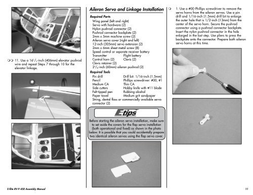
11. Use a 16 1 / 2 -inch (406mm) elevator pushrodwire and repeat Steps 7 through 10 for theelevator linkage.Aileron Servo and Linkage InstallationRequired PartsWing panel (left and right)Servo with hardware (2)Nylon pushrod connector (2)Pushrod connector backplate (2)2mm x 5mm machine screw (2)Aileron servo cover (right and left)12-inch (305mm) servo extension (2)2mm x 6mm sheet metal screw (8)Speed control or separate receiver batteryTransmitterFlight batteryControl horn (2) Clevis (2)Clevis retainer (2)2 3 / 8 -inch (60mm) aileron pushrod (2)Required ToolsPin drillDrill bit: 1/16-inch (1.5mm)Pencil Phillips screwdriver: #00, #1Medium CA Thin CASide cutters <strong>Hobby</strong> knife with #11 bladeFelt-tipped pen Rubbing alcoholPaper towel Medium grit sandpaperString, dental floss or commercially available servoconnector (2)1. Use a #00 Phillips screwdriver to remove theservo horns from the aileron servos. Use a pindrill and 1/16-inch (1.5mm) drill bit to enlargethe outer hole that is 1/2-inch (13mm) from thecenter of the servo horn. Secure the pushrodconnector using a pushrod connector backplate.Insert the nylon pushrod connector in the holeenlarged in the last step. Use pliers to press thebackplate onto the connector. Prepare both aileronservo horns at this time.Before starting the aileron servo installation, make sureto set aside the covers for the flap servo installation(both operational and fixed) as shown in the photobelow. It is possible that you could accidentally preparetwo identical aileron servos using the flap servo cover.E-flite RV-9 450 Assembly <strong>Manual</strong>11