Download PDF (0.84 Mb) - Verotec
Download PDF (0.84 Mb) - Verotec
Download PDF (0.84 Mb) - Verotec

Create successful ePaper yourself
Turn your PDF publications into a flip-book with our unique Google optimized e-Paper software.
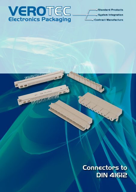
VEROTECElectronics PackagingConnectors toDIN 41612
Connectors to DIN 41612Connectors conforming to DIN 41612<strong>Verotec</strong> maintains a range of connectors that conformto the DIN 41612 norm and some that could be termed enhancedstandard developed from customers special requirements.12111214 DIN ConnetorsConnector qualification<strong>Verotec</strong> connectors conform to DIN 41612, Part 5 with regard totheir nominal values, claims and testing.PerformanceclassMatingcyclesSurfaces1 500 Contact area gold platedTermination Tin plated*2 400 Contact area gold platedTermination Tin plated3 50 Contact area gold platedTermination Tin plated* <strong>Verotec</strong> connectors in general meet performance class 2: Lifespan 400 mating cycles. 200 cycles, then 4 days of gas testing.Measurement of the resistance. 200 mating cycles followed byvisual inspection. No degradation from surface material throughto the sub-material, and no lessening of functionality.Gas test10 days4 daysRating curves. (Operating current/AMBIENT temperature)—345678910131415161718Selector19292030VDE 0110 b/2.79, Table 4Minimum values of air and creepage distances in mmReference voltages (to Table 1) upto:DC Voltage V 15 36 75 150 300 450 600AC voltage(rms)V 12 30 60 125 250 380 500Insulation group L 0,06 0,1 0,15 0,25 0,5 0,8 1,1Aoa 0,1 0,15 0,2 0,35 0,7 1,1 1,5Insulation group L 0,15 0,2 0,25 0,4 0,8 1,2 1,6Aa 0,2 0,25 0,35 0,5 1 1,5 2Insulation group L 0,4 0,5 0,7 1 1,6 2,4 3Ba 0,6 0,8 1 1,3 2 3 4b 0,8 1 1,3 2 3 4 5,5Insulation groupCInsulation groupDL 0,8 1 1,2 1,6 2,5 3,5 4,5a 1,2 1,5 1,7 2,2 3 4,5 6b 1,7 2 2,3 3 4 6 8L 1,6 1,8 2 2,5 3,5 5 6,5a 2,3 2,6 3 3,5 5 7 9b 3,2 3,5 4 5 7,5 10 13L = Air distance a , b = Creep distance as Table 3VDE 0110 b/z.79, table Creeping current strength212223242526272831323334353637Creeping currentstrength1)(Minimum value)KB 100Creeping-distances2)without ribs with ribs ( 8a)ba + b2KB 380a + b2aKB 600 a aSelector1) DIN 53480/VDE 03032) For insulation group Ao and A generally creepage-distance a14.02 UK Tel: +44 (0)2380-246900 sales@verotec.co.ukUSA Tel: 603.821.9921 sales@verotec.us
Connectors to DIN 41612HEAVY DUTY CONNECTOR CODING DEVICEThis coding device is suitable for use with DIN 41612 types B, C &D connectors. It will prevent incorrect board insertion and costlymiss-mating. The device is manufactured from zinc alloy to BS1004A and offers a very strong polarizing feature that is easy andquick to assemble.Ordering informationDescriptionOrder codeCompatible connectors B, C and D, 10 kits per pack 41-24324GAn alternative coding device is available in red plastic.Order codeB,C and D, 10 kits per pack 17-2856EOrdering informationType Order code DIN description ✶POS. Description class3 ROW FORM C male 64/96 17-2876 C64M - C1A 8 Dip solder, angled. Contacts: full rows A & C 23 ROW FORM C male 96/96 17-2622 C96M - C1A 1 Dip solder, angled. Contacts: full rows A, B & C 23 ROW FORM C female 32/96 17-2875 M C32F - C1H 2 Wire wrap. Contacts: even numbers rows A & C 23 ROW FORM C female 64/96 17-2874 C64F - C1H 3 Wire wrap. Contacts: full rows A & C 23 ROW FORM C female 64/96 17-2624 C64F - C1D 4 Dip solder. Contacts: full rows A & C 23 ROW FORM C female 64/96 17-2625 C64F - C1W 5 Solder eyelet. Contacts: full rows A & C 23 ROW FORM C female 96/96 17-2479 C96F - C1D 6 Dip solder. Contacts: full rows A, B & C 23 ROW FORM C female 96/96 17-2626 C96F - C1H 7 Wire wrap. Contacts: full rows A, B & C 22 ROW FORM D male 32 way 17-2873 D32M - C1A 9 Dip solder, angled. Contacts: full rows A & C 22 ROW FORM D female 32 way 17-2872 D32F - C1H 10 Wire wrap. Contacts: full rows A & C 22 ROW FORM D female 32 way 17-10720 D32F - C1D 11 Dip solder. Contacts: full rows A & C 22 ROW FORM D female 32 way 17-10110 M D32F - C1W 12 Solder eyelet. Contacts: full rows A & C 23 ROW FORM F male 48 way 17-2631 M F48M - C1A 13 Dip solder, angled. Contacts: full rows B, D & Z 23 ROW FORM F female 48 way 17-2636 M F48F - C1H 14 Wire wrap. Contacts: full rows B, D & Z 23 ROW FORM F female 48 way 17-45497 M F48F - C1W 15 Solder eyelet. Contacts: full rows B, D & Z 2FORM H male, 11 way * 17-10112 M H11M - C2A 16 Faston/dip solder, angled, LP 32** 1FORM H female, 11 way * 2 17-10113 H11F - C2S 17 Faston 6.3 x 0.8mm 1FORM H female, 11 way * 2 17-10137 M H11F - C2S 18 Dip solder, 2 per contact 1FORM H male 15 way * 17-10210 H15M - C2G 19 Faston 6.3 x 0.8mm, LPZ32** 1FORM H male 15 way * 17-10493 H15M - C2A 20 Dip solder, angled, LPZ32** 1FORM H female 15 way * 2 17-10223 M H15F - C2D-90° 21 Dip solder, angled 1FORM H female 15 way * 2 17-10115 H15F - C2S 22 Faston 1FORM H female 15 way * 2 17-10144 M H15F - C2Sr 23 Screw connection 1FORM H female 15 way * 2 17-46844 M H15F - C2W 24 Solder eyelet 1FORM H female 15 way * 2 17-10224 M H15F - C2D 25 Dip solder, 2 per contact 1FORM H female 15 way * 2 17-46842 H15F - C2D 26 Solder, 4mm long 1FORM H female 15 way * 2 17-46843 M H15F - C2D 27 Solder, 13mm long 1FORM H 15 male 10 + 2 way* 17-10038 M H15M - 10WVZ 28 32+2 HA/W 28 10 Angled dip solder/faston + 2 dip solder/screw,LPZ32**FORM H 15 male 7 + 4 way* 17-10235 M H15M - 7WVZ 29 32+4 HA/W 29 2 + 2 dip solder/screw + 7 angled dip solder/fastonFORM H 15 female, 10 + 2 way * 2 17-10039 M H 15 F 10 SR+2 HA/L 30 10 screw, 2 solder 1FORM H 15 female, 10 + 2 way * 2 17-10138 H 15 F 10 FA+2 HA/L 31 10 faston, 2 solder 1FORM H 15 female, 7 + 4 way * 2 17-10236 M H 15 F 7 FA+4 HA/L 32 2 solder, 7 faston, 2 solder 1FORM M male mixed 24 + 7 way * 17-24311 Male mixed, form M 33 Dip solder, angled 24 + 7, LPZ32** 2FORM M female mixed 24 + 7 way * 2 17-24312 M Female mixed, form M 34 24 wire wrap, 7 faston 2FORM M male mixed 24 + 7 way * 17-10225 Male mixed, form M 35 Dip solder, angled. 24 + 7 Dip solder/faston, LPZ32** 2FORM M female 24 + 7 way * 17-10227 Female mixed, form M 37 24 + 7 Dip solder 214 DIN ConnectorsM = Denotes minimum order quantity, please contact our sales office.* With integrated polarisation ** Leading pin position Use coding wedge 17-10234 (Pk 10)2 Use coding wedge 17-10064 (Pk 10)Order coding keys separatelyUK Tel: +44 (0)2380-246900 sales@verotec.co.ukUSA Tel: 603.821.9921 sales@verotec.us14.03
Connectors to DIN 416123 ROW FORM CMALE 64/96,96/9614 DIN Connetorsn Angled dip solder terminationsn Rows on 2,54mm pitchn For PCBs with nominal thickness of 1.6mmn Height of 11mmn Selectively hard gold plated contacts which ensure areliable contact at high connection forcesn Discrimination notches prevent incorrect connectionH Position No’s. 8 & 13 Row form C (male 64/96, 96/96)3 ROW FORM CFEMALE 32/96, 64/96, 96/96n Wire wrap, solder eyelet or dip solder terminationsn Three rowsn Selectively gold plated contacts, zinc plated terminationsH Position No’s. 2 to 73 Row form C (female 64/96, 96/96)14.04 UK Tel: +44 (0)2380-246900 sales@verotec.co.ukUSA Tel: 603.821.9921 sales@verotec.us
Connectors to DIN 416122 ROW FORM DMALE 32 WAYFEMALE 32 WAYn Two rows, inter-row spacing 5.08mmn Angled dip solder, Wire-wrap, solder eyelet or dip solderterminationsn Height 11mmn Discrimination notches in the housing prevent incorrectconnectionn Coding for connector construction forms are availablen Selectively gold plated contacts, zinc plated terminationsH Positions 9 to 123 ROW FORM FMALE 48 WAYFEMALE 48 WAYn Three rows, inter-row spacing 3.81mmn Connectors with higher insulation to VDE 0110Group C 380V/450Vn Operating current 4.0A at 70°Cn Angled dip solder, solder eyelet or wire wrap terminations on5,08mm matrixn Selectively gold plated contacts, zinc plated dip solderterminationsn For PCBs with a nominal thickness of 1.6mmn Discrimination notches prevent incorrect connectionn Selectively gold plated contacts, zinc plated solder or wire wrapterminationsn Higher insulation body, to VDE 0110 Group C 380V / 450 Vn Solder termination 1mm squareH Positions 13 to 152 Row form D (male and female 32 way)14 DIN ConnectorsCONNECTORS WITH INTEGRATED POLARISATIONMany of the following connectors can be polarised without lossof contact. Coding wedges, which should be ordered separately,are fitted to the female. The corresponding break-out feature isremoved from the mating male.3 Row form F (male and female 48 way)Connectors with integrated polarisationUK Tel: +44 (0)2380-246900 sales@verotec.co.ukUSA Tel: 603.821.9921 sales@verotec.us14.05
Connectors to DIN 4161214 DIN ConnetorsFORM HWITH INTEGRATED POLARISATION MALE AND FEMALE 11 AND 15WAYn Specially developed for PSUs; operating voltage 500v.insulation group C to VDE 0110 when using insulated sheaths.n First make, last break contact position z32n DIP solder, solder eyelet, screw or faston terminations (A6,3 x0,8mm to DIN 46244)n Low profile version for backplane applicationsn Maximum 15A operating currentn On Form H Male, 11 way, 11, pin, one row; terminations onpitch of 7,62mmn For 15 way male body has integrated cooling feature that canbe removed without special toolsn Female moulding can be fitted with coding wedges for polarisationH Positions 16 to 27Form HFORM H15WITH INTEGRATED POLARISATION ( EXCEPT SCREW TYPE) MALEAND FEMALE 10+2 AND 7+4 WAYn Mixed contacts with separated areas for high current applications to DIN41612 requirementsn Specially developed for PSUs: operating voltage 500v.insulated group C to VDE 0110 when using insulated sheaths.n First make, last break contact position 32n 2 or 4, 50A contacts inserted into female body after soldering.Male 50A contacts DIP solder or screw termination for directconnection to busn 7 or 10, 15A contacts with DIP solder/faston or screw terminationH Positions 28 to 32Form H1514.06 UK Tel: +44 (0)2380-246900 sales@verotec.co.ukUSA Tel: 603.821.9921 sales@verotec.us
Connectors to DIN 41612FORM MMALE AND FEMALE MIXED 24 + 7 WAYn Mixed connector with two separated areas for electronic andheavy current wiringn Electronic wiring on 24 contacts (first mate last break contact z24)n Heavy current wiring on 7 contacts (first mate last break contact z32)n Selectively gold plated and zinc plated angled terminations forautomatic dip solder (Electronic contacts)H Positions 33 & 3414 DIN ConnectorsFORM MWITH INTEGRATED POLARISATION MALE AND FEMALE 24+7 WAYn 24 electronic and 7 heavy current (15A)n First mate, last break contacts in both areasn Dip solder and wire wrap (22mm x 1❏) terminationsn Coding without loss of contactsn 8 coding positions = max 70 combinationsn Selectively gold plated contacts in the electronic area and silver plating inthe heavy current section give excellent contact performanceH Positions 35 to 37Form M (male and female mixed 24 + 7 wayForm M with integrated polarisation (male and female 24 +7 way)UK Tel: +44 (0)2380-246900 sales@verotec.co.ukUSA Tel: 603.821.9921 sales@verotec.us14.07
Connectors to DIN 41612 Notes14 DIN Connetors14.08 UK Tel: +44 (0)2380-246900 sales@verotec.co.ukUSA Tel: 603.821.9921 sales@verotec.us