Download PDF (2.32 Mb) - Verotec
Download PDF (2.32 Mb) - Verotec
Download PDF (2.32 Mb) - Verotec
- No tags were found...

Create successful ePaper yourself
Turn your PDF publications into a flip-book with our unique Google optimized e-Paper software.
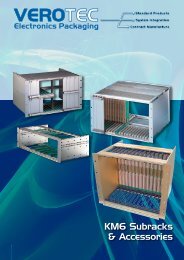
VEROTECElectronics PackagingKM6-II Subracks
Dimensional Criteria: KM6-II Subrack Systems1 KM6 SubracksUNIVERSAL SUBRACK LAYOUTCard guideRear extrusionFront panelassemblyPCB mountingbracketsUNIVERSAL SUBRACK3U4U6U7Uor9U12,0*Front panel thickness 2,50300/360/420STANDARD SUBRACK LAYOUT1mm insulating or conductivespacer stripused when mounting PCBbackplaneStandardbackplaneextrusionSTANDARD SUBRACKType B + CDIN 41612connector3Uor6U3U SUBRACK FRONT VIEW84HP Usable front apertureFront panel or plug-in unitidentification hole lines upwith printed identificationon top front extrusionDrawing not to scaleDrawing not to scale1.18UK Tel: +44 (0)2380-246900 sales@verotec.co.ukUSA Tel: 603.821.9921 sales@verotec.us
KM6-II Subracks: StandardKM6-II ‘Standard’ Subracks are strong and versatile, whilst offering ease ofassembly. The tie bars are of a larger section to improve both rigidity andguide location, and versions suitable for 220mm boards will accept 160mmboards. The end plates are symmetrical in design, allowing 19” end plateangles to be fitted on either the front or rear of the frame, thus providingeasy rear access.Features Versions for backplane and DIN 41612 connector Strong and versatile Conforms to IEC 60297-3 Totally conductive components 160mm mounting in 220mm versions Provision for fitting 19” angles front or rear 3U and 6U heights 160 and 220mm board compatible 84 and 42 HP widths available Simple assembly - single screw fixing of tie-bars No adjustment required after assembly Pre-tapped holes and machine screws throughout Supplied as a complete kit Reduced height end plates to accept chassis supports Available with or without front handles3U and 6U Standard subracks1 KM6 Subracks'Standard' subracks can be supplied with backplane or DIN 41612 connectormounting rear extrusion. 84HP kits are available with, or without, fronthandles. Backplane extrusions can be converted to DIN 41612 by means of aseparate connector frame.Reversed AssemblyThe kit includes rear tie bars and is complete with all tapped strips. In orderto maintain the front panel/connector geometry a suitable backplane spacer,either insulating or conductive, must be used on backplane versions.Contents of kitDescription Qty. Material/FinishEnd plates 2 2mm aluminium BS 1470 5251-H24(NS4 H6), conductive clear chromateEnd plate angles 2 Aluminium Ally BS1474-6063-T6anodisedFront tie bars 2 Aluminium alloy BS 1474 6063T6,conductive clear chromateRear tie bars 2 Aluminium alloy BS 1474 6063T6,conductive clear chromateCentre rear tie bar (6U only) 1 Aluminium alloy BS 1474 6063T6,conductive clear chromateTapped stripsMS Zinc passivateBackplane variants (3U/6U) 4/6DIN 41612 variants 2(the rear extrusions are fully tapped)All fixingsAssembly instructionsOptional: handles 2160 Board in 220 subrackBackplane ExtrusionsBackplane spacers(order separately)CentreTapped stripTop and bottomDIN 41612 ExtrusionsTop and bottomCentreTapped M2,5UK Tel: +44 (0)2380-246900 sales@verotec.co.ukUSA Tel: 603.821.9921 sales@verotec.us1.19
KM6-II Subracks: StandardKM6-II Subrack, backplane mounting1 KM6 SubracksOrdering informationHeight Depth (mm) Width (HP) Order code Order codewithout handles with handles180 42 950-202583 –3U240 42 950-202587 –180 84 950-202581 950-232563240 84 950-202585 950-232654180 42 950-202584 –6U240 42 950-202588 –180 84 950-202582 950-232604240 84 950-202586 950-2326053U SubrackNotes:1. In order to maintain the correct geometry between the front panels and backplaneconnectors a suitable backplane spacer is required. Either insulating or conductivetypes (1mm thick) may be used, and must be located between the rear tie bar andthe backplane - refer to page 34.2. Backplane mounting tie bars can be converted to accept DIN 41612 connectors byfitting adaptor kits or rails - refer to page 34.6U Subrackand(overall depth)Rear tie bar(inc tapped strips)and(overall depth)KM6-II Subrack, DIN 41612 connector mountingOrdering informationHeight Depth (mm) Width (HP) Order code Order codewithout handles with handles3U180 84 950-232050 950-232568240 84 950-232051 950-2325696U180 84 950-232052 950-232607240 84 950-232053 950-232608Centre reartie barEnd plateFront tie bar(inc tapped strips)End plateanglesOrder separatelyProductPageDimensional DetailFRONT VIEWDIN 41612 Connector Adaptor kits 34Backplane Spacers 34PCB or Plug-in Unit Guides 35PCB Grounding clip 36PCB Retainers and guide nose extensions 37PCB Ejectors 38SIDE VIEWDivider kits 41 –43Rear Dust Covers 44Top, Bottom and Rear Covers – non-EMC 44Horizontal PCB Mounting Modules 45Subrack Handles 46Connector Protection Kits 47Fixing Screws 48PLAN VIEWNote: The conductive finish gives excellent electrical conductivity but is more easily markedthan anodising. During assembly care should therefore be taken to avoid the deposition ofgrease and oil, particularly on the visible surfaces.1.20UK Tel: +44 (0)2380-246900 sales@verotec.co.ukUSA Tel: 603.821.9921 sales@verotec.us
KM6-II Subracks: UniversalUniversal KM6-II subracks are strong, versatile and easy to assemble. Thetie bars are of large section for rigidity and are secured using two fixingscrews into counterbored holes. The screws thus act as location dowelspromoting a high degree of accuracy during construction.Features Strong and versatile Two screw fixing of tie bars Conforms to IEC 60297-3 Total versatility permits wide range of configurations Available in kit or piece-part form Accurate location for first time assembly Rugged construction Pre-tapped holes and machine screws throughout EMC conversion (see pages 23 – 27) No location mouldings required With or without front handles Provision for fitting 19” angles front or rear3U and 6U Universal subracks1 KM6 SubracksThis version, as the name implies, has the capability of housing Eurocardsof different sizes in a variety of configurations.The frame can be constructed from standard parts in 3U, 4U, 6U, 7U and 9Uheights.The 240mm, 300mm, 360mm or 420mm deep endplates, incorporatea series of punched holes so that the tie bars can be assembled at anyrequired position on a 12mm pitch. 300mm and greater depths also havea pattern of additional holes for fixing the chassis system. 84 HP variantsare offered in Backplane or DIN 41612 connector mounting and are suppliedwith or without front handles. DIN 41612 rear tie bars are fully tapped.Reversed SubrackNote: 4U and 7U versions can only be ordered from piece parts. Alternative versionsof 3U, 6U and 9U subracks can also be ordered from piece parts.Contents of kitsDescription Qty. Material/FinishEnd plates 2 2mm or 2,5mm aluminium BS 1470 5251-H24 (NS4 H6) conductive clear chromateEnd plate angles 2 Aluminimum alloy BS1474-6063-T6anodisedFront tie bars 2 Aluminium alloy BS 1474-6063-T6conductive clear chromateRear tie bars - 2 - 3U Aluminium alloy BS 1474-6063-T63 - 6U conductive clear chromate4 - 9UTapped stripsBackplane variants- 4 - 3U MS zinc passivate6 - 6U MS zinc passivate8 - 9U MS zinc passivateDIN 41612 variants 2 Aluminium alloy BS 1474 6063T6(the rear extrusions are fully tapped) conductive clear chromateAll fixingsAssembly instructions 1Optional: handles 2EMC conversionBackplane ExtrusionsBackplane spacers(order separately)DIN 41612 ExtrusionsCentreTapped stripTop and bottomTop and bottomCentreTapped M2,5UK Tel: +44 (0)2380-246900 sales@verotec.co.ukUSA Tel: 603.821.9921 sales@verotec.us1.21
KM6-II Universal and KM6-EC Subracks: EMC ConversionKM6-II EMC conversion kitsKM6-II Universal subracks and some sizes of KM6-EC can be retrospectivelyEMC screened by the addition of covers and suitable front and rear panels.Two Basic types of screening cover are available:OVERALL, (Fig. 1) which provide a screen over both the card area and therear connector/backplane area. In this version, the rear of the subrack iscompleted by the addition of conventionally fixed panels, either full width orin combinations of lesser width front panels.PCB AREA ONLY (Fig. 2) This application requires a motherboard/backplanewhich is specifically designed to provide rear screening using ground planetechnology. With this geometry, only the front aperture requires screeningpanels.1 KM6 SubracksCovers are generally available in ventilated and unventilated forms. They aredesigned to maintain intimate contact with the end plates by means of screwsand internal flanges. At the interface with the extrusions, the covers havepatented dimples in such a way as to provide an interference fit with a slot inthe extrusion. The concept of this slot ensures that the card guide locationholes are within the screened area of the subrack and also provides additionalscreening by introducing a labyrinth around the edge of the cover.‘A guide to the EMC screening of subracks’ on page 12 discusses the effectsof various configurations on the overall performance, with particularattention to the use of RFI fingers.Ordering an EMC screened subrack Select a Universal subrack kit to suit your card size using table below.Note that, for instance, it is not possible to EMC screen a 220mm long card ina 240 deep subrack.KM6-II EMC conversion kitsFigure 1EMC covers extended overbackplane/connector areaRear closed by suitableEMC panel(s) Select an EMC conversion kit to suit your subrack and card size (seepage 24 for Overall Depth Covers and page 25 for PCB Depth Covers).Note – for screening 42HP subracks please refer to note 2 on page 34 Select front and rear panels as appropriate (see page 27). Identify total quantity of RFI finger strips required according to thedesired performance level of the final assembly. (See page 12 for guide andpage 24 for EMC finger strips).Front closed by suitableEMC panel(s)Typical hole pattern 5mm square holeson a 6,35mm pitchKM6-II Universal subracksPCB Configurations accepted when using EMC conversions and cover kitsHeight PCB Depth (mm) End Plate (mm) Order code160 2403U 160/220 300 Refer to page 22160/220 360160 2406U160/220 300160/220 360Refer to page 22160/220/280/340 420160 2409U 160/220 360 Refer to page 22160/220/280/340 420Figure 2EMC cover for board area onlyBackplane forms rear screenFront closed by suitableEMC panel(s)UK Tel: +44 (0)2380-246900 sales@verotec.co.ukUSA Tel: 603.821.9921 sales@verotec.us1.23
KM6-II Universal Subracks: EMC ConversionEMC Conversion kits – overall depthThis kit contains the parts required to convert an 84HP subrack for EMC.1 KM6 SubracksNotes:1. EMC front and rear panels and EMC fingers should be ordered separately tosuit requirements – please refer to page 27.2. 42HP card frames can be effectively screened by ordering the individualcovers, rear closing angles and front panels featured on pages 26,together with the EMC finger strip detailed below.Contents of kitDescription Qty. Material and finishPlain tie bars 2 Aluminium alloy BS1474-6063-T6conductive clear chromateTapped strips 2 MS Zinc passivateRear closing angles 2 Aluminium Ally BS1474-6063-T6anodisedTop and bottom covers 2 0,9mm Aluminium alloy(either ventilated or unventilated)conductive clear chromateAll fixingsFigure 3EMC Covers extended overbackplane/connector areaRear closed by suitableEMC panel(s)KM6-II EMC ConversionOrdering InformationHeight Ventilated PCB Depth End Plate Order(mm) (mm) Code3UNo 160 240 950-240574Yes 160 240 950-2405756UNo 160 240 950-240576Yes 160 240 950-2405779UNo 160 240 950-240578Yes 160 240 950-2405793UNo 160/220 300 950-240580Yes 160/220 300 950-2405816UNo 160/220 300 950-240582Yes 160/220 300 950-2405833UNo 160/220 360 950-240584Yes 160/220 360 950-2405856UNo 160/220 360 950-240587Yes 160/220 360 950-2405889UNo 160/220 360 950-240589Yes 160/220 360 950-2405906UNo 160/220/280/340 420 950-240562Yes 160/220/280/340 420 950-2405639UNo 160/220/280/340 420 950-240564Yes 160/220/280/340 420 950-240565Front closed by suitableEMC panel(s)Typical hole pattern 5mm square holeson a 6,35mm pitchRFI Finger stripRFI Finger stripSupplied in lengths of 381mm consisting of 60 fingers. The fingers are selfadhesive for easy application and replacement in the field. The quantity of fingersfitted at any panel/subrack interface is selected according to the performancerequired from the overall screen. Please see page 12 for details. They can be cutusing a sharp pair of scissors, taking care to avoid crushing during cutting.RFI finger strip material: Beryllium copperOrdering informationDescription Length Order codeRFI Finger strip 381mm (60 fingers) 930-2382431.24UK Tel: +44 (0)2380-246900 sales@verotec.co.ukUSA Tel: 603.821.9921 sales@verotec.us
KM6-II Universal Subracks: EMC ConversionFigure 4Board area only EMC cover kitsBoard area only EMC cover kits (Fig.4) For use in situations where the backplaneforms the rear EMC screen, these ventilated covers fit between the front, andbackplane, extrusion only.Select by board depth and subrack width (84HP only); end plate depth is not aconsideration.Contents of kitDescription Qty. Materials/FinishTop and Bottom Covers 2 0,9mm Aluminium alloy(ventilated)conductive clear chromateFixingsEMC Cover for board area onlyBackplane forms rear section1 KM6 SubracksOrdering informationDescriptionOrder code84HP x 160 Ventilated EMC cover 950-25937184HP x 220 Ventilated EMC cover 950-259372This performance graph shows the results from randomly selected KM6-IIsubracks, 6Ux84HPx360 with ventilated and unventilated EMC covers. Bothwere fitted with overall closing panels and a maximum quantity of BeCu fingers.Measurements were taken at all six faces and the results shown in the graph arecalculated as follows:H field – minimum figuresKM6-II Shielding EffectivenessE field – minimum figures up to 30MHz above 30MHz the figures for allfaces are plotted on a rolling seven point average.A detailed discussion of our EMC test facility and procedures is shown in ourseparate leaflet 'The Science of Compliance'. If you require a copy, pleasecontact your local sales office.Attenuation - dBPlain Version with full BeCuVentilated Version with fullPlain Version with full BeCuE FieldH FieldVentilated Version with full BeCuFrequency -MHzUK Tel: +44 (0)2380-246900 sales@verotec.co.ukUSA Tel: 603.821.9921 sales@verotec.us1.25
KM6-II Universal Subracks: EMC Conversion - piece parts1 KM6 SubracksKM6-II EMC Conversion: Top and Base covers – overall depthThe ‘Overall’ EMC conversion kits are also available in their constituent parts.In addition to the 84HP versions, a small range of ventilated overall covers isavailable in 42HP and 60HP widths. In order to fit these, it is necessary to orderreduced width front extrusions and tapped strips, M4 fixing screws and rearclosing angles.Contents of kitDescription Qty. Material/FinishCovers 2 0,9mm aluminium alloy, conductive clear chromateAll fixingsFront tie barPlain rear tie bar (84HP) or additional fronttie bar (42 or 60HP)Top/bottom coverRFIFingerstripRear closing angleOrdering InformationWidth Ventilated PCB Depth (mm) End Plate (mm) Order code42HPNo 160 240 –Yes 160 240 950-25941760HPNo 160 240 –Yes 160 240 950-25941884HPNo 160 240 950-240557Yes 160 240 950-24055342HPNo 160/220 300 –Yes 160/220 300 950-259419No 160/220 300 950-240556Yes 160/220 300 950-24055284HPNo 160/220 360 950-240559Yes 160/220 360 950-240554No 160/220 420 950-240558Yes 160/220 420 950-240555M3 x 5Rear Closing AnglesThese are fitted at the rear in conjunction with rear mounting tie bars. EMCBeryllium copper fingers should be ordered separately to maintain the shieldbetween the subrack and EMC panels.Contents of kitDescription Qty. Material/FinishAngles 2 AL extrusion, conductive clear chromateOrdering informationDescriptionOrder code3U Rear closing angles 950-2405494U Rear closing angles 950-2592786U Rear closing angles 950-2405507U Rear closing angles 950-2592799U Rear closing angles 950-240551Rear Mounting Tie BarsTwo should be ordered per subrack. 84HP version use a plain tie bar. Otherwidths use standard front tie bars. Sold in singles. Two tapped strips andeight fixings are also required.Ordering informationDescription: Rear mounting barsWidth Type Order code84HPPlain tie bar 950-221909Tapped strip 950-202001Front tie bar top 950-20274360HP Front tie bar bottom 950-202742Tapped strip 950-202740Front tie bar top 950-20273642HP Front tie bar bottom 950-202735Tapped strip 950-202739Tie bar fixing screws: Pack 100 (4 per tie bar required) 950-2027341.26UK Tel: +44 (0)2380-246900 sales@verotec.co.ukUSA Tel: 603.821.9921 sales@verotec.us
KM6-II Universal Subracks: EMC Conversion - front panel optionsIndividual two-part EMC panelsAvailable in various widths as blanking panels or for mounting circuit boards.Copper fingers are required for maintaining continuity between neighbouringpanels. 6U and 9U panels have type C handle format.Note that these two-part panels, although still available, have been replacedwith single-part extruded versions with gaskets fitted. Full details can befound from page 2.21 onwards of the Front Panels and Plug-in Units section.Contents of kitDescriptionPanel inc. fixingsHandles and idents (1-3U, 2-6U and 9U)FinishFacia panel etch and clear anodise,inner panel conductive clear chromateIndividual EMC panels1 KM6 SubracksOrdering informationDescription: Individual EMC panelHeight Width Qty. Order code4HP 1 951-2429633U6HP 1 951-2429648HP 1 951-24296524HP 1 951-2429684HP 1 951-2429696U6HP 1 951-2429708HP 1 951-24297112HP 1 951-242972Type 1Type 2Overall closing panelsThese full width (84HP) closing panels can be used at the front or rear ofthe subrack and make contact with the end plates and tie bars as describedbelow.Type 1 which is secured by twelve captive screws and is available for installationswhere access is seldom necessary. Contact to the end plates is achievedusing beryllium copper fingers.Type 2 is secured by four captive screws only, relying on beryllium copperfingers to maintain contact on all four edges.Type 3 is a horizontally hinged panel which relies almost entirely on berylliumcopper fingers for contact on all four edges, having only two captivescrews. A special finger strip is provided with the kit for the bottomflange only.Types 2 and 3 are particularly useful in situations where frequent access islikely to be required.Overall closing panelsType 3Finger strip supplied forthis flangeContents of kitDescriptionPanel inc. fixingsHandles and idents (Type 2 only)FinishFacia panel etch and clear anodise,inner panel conductive clear chromateOrdering informationDescription: Overall closing panelsType Qty Width Height Order code3U 950-2026941 1 84HP 6U 950-2026959U 950-2026963U 951-2429572 1 84HP 6U 951-2429589U 951-2429593U 951-2429604U 951-2592843 1 84HP 6U 951-2429617U 951-2592859U 951-242962UK Tel: +44 (0)2380-246900 sales@verotec.co.ukUSA Tel: 603.821.9921 sales@verotec.us1.27
KM6-II Subracks: Piece parts1 KM6 SubracksKM6-II Universal Subrack – Piece PartsIt is possible to order KM6-II ‘Universal’ subracks from piece parts. This allowsspecial configurations to be achieved. 4U and 7U Universal subracks can only beordered from piece parts. All basic components are detailed on the next four pages.What must I order?Typical Example:–To achieve a basic 3U Universal subrack you must order the following:Item Quantity PageEnd plates 2 29End plate angles 2 29Front tie bar - top 1 30Front tie bar - bottom 1 30Rear tie bars (backplane or connector mounting) 2 31–32Tapped strips 2 or 4 34Tie bar fixings 16 (sold in pks. 100) 48KM6-II Universal subrackRear tie barFront tie barEnd plate angle240, 300, 360 or 420KM6-II Universal SubrackOrder separatelyProductPageEMC Covers/conversion kit 23 – 26EMC Front and rear panels 27Backplane spacers 34DIN 41612 connector mounting 34PCB or Plug-in module guides 35PCB Grounding clips 36Positive guide retention – tapped strips 36PCB Retainers and guide nose extensions 37PCB Ejectors 38Divider Kits 41 – 43Rear Dust covers – non-EMC 44Top and Bottom covers – non-EMC 44Horizontal mounting modules 45Subrack handles 46Connector protection kits 47Fixing screws 48Note: The conductive finish gives excellent electrical conductivity but is more easily marked than anodising. During assemblycare should therefore be taken to avoid the deposition of grease and oil, particularly on the visible surfaces.1.28UK Tel: +44 (0)2380-246900 sales@verotec.co.ukUSA Tel: 603.821.9921 sales@verotec.us
KM6-II Subracks: Piece partsEnd PlatesUniversal end plates are punched on a 12mm pitch along their length toenable tie bars to be mounted to suit customer applications.On 300mm and deeper versions there is also a pattern of intermediate holesto permit the fixing of a chassis or support system.Identifications are stamped on the end plate to assist in tie bar location.Endplates are sold singly (i.e. 2 required for each subrack).The 4U x 360 and 7U x 420 versions can be assembled as 3U/6U + 2 x ½U or3U/6U + 1U.End plates and end plate anglesEND PLATES3U1 KM6 SubracksOrdering informationDescription: End platesHeight Depth Thickness Qty. Order code240mm 2mm 1 950-2027873U 300mm 2mm 1 950-221911360mm 2mm 1 950-2027904U240mm 2,5mm 1 950-202618360mm 2,5mm 1 950-202620240mm 2mm 1 950-2027886U300mm 2,5mm 1 950-221912360mm 2,5mm 1 950-202791420mm 2,5mm 1 950-2027937U 420mm 2,5mm 1 950-259286240mm 2,5mm 1 950-2027899U300mm 2,5mm 1 950-224197360mm 2,5mm 1 950-202792420mm 2,5mm 1 950-202794Material: 2,0 or 2,5mm Aluminium BS1470 5251-H24 (NS4 H6), conductivefinishPitches at 48mmFor 4U or 7U dimensions add 44,45 to the 3U or 6U height dimensions. 4Uand 7U have a row of holes to suit 3U components.6U9UPIitches at 44,45mmCONDUCTIVE FINISHEnd Plate AnglesOrdering informationDescription: End plate angles Order code Order codeHeight Thickness Qty. With handle holes w/out handle holes3U 2mm 1 950-232632 950-2027834U 2,5mm 1 – 950-2026166U2mm 1 950-232633 950-2027842,5mm 1 950-232635 950-2027857U 2,5mm 1 – 950-2592879U 2,5mm 1 – 950-202786END PLATE ANGLES6U-265,99U-399,2MM3U 132,5Note: 6U angles vary according to end plate thicknessMaterial: Aluminium alloy extrusion BS1474-6063-T6, anodised finishANODISEDUK Tel: +44 (0)2380-246900 sales@verotec.co.ukUSA Tel: 603.821.9921 sales@verotec.us1.29
KM6-II Subracks: Piece parts1 KM6 SubracksKM6-II Front Tie BarsKM6-II front tie bars feature a screw fixing system using a unique dowelscrewarrangement which ensures accurate location and subrack rigidity. Anadditional slot is provided which, when fitted with a tapped strip, enables pcband module guides to be secured using M2,5 x 5mm screws, thereby offeringgreater security and strength (see figure 8).Provision is also made for the fitting of dust/EMC covers, without the needfor additional seals, whilst still maintaining a high level of EMC screening.Normal front extrusions have slot identification printed along their length toaid guide location. Top versions also have a printed ident on the front face forpanel location.In addition to the normal front extrusion, there are other types:KM6-II front tie barsPLAINEMCwhich has no guide location holes; this extrusion is included inconversion kits and can also be used for just attaching additionalpanels (e.g. for rear socket mounting).9,90NormalLIPLESS which has normal guide location holes but offers two facilities; ifused as a height dividing extrusion, it is possible to use overallfront panels (see figure 6); it will also fit within an EMC screen,permitting the recessing of cards (see figure 7).24,002,90 49,858,50LiplessThese extrusions are supplied in lengths of 84HP and can easily be cut tolength to suit other width requirements. These tie bars are not silk screenprinted.24,0046,95Contents of kitItem/DescriptionMaterial/Finish1 tie bar Aluminium alloy BS 14746063T6conductive clear chromate13,3024,0049,85Injector/ejectorOrdering informationDescription Qty. Order code24HPTie bar - top front 1 950-202796Tie bar - bottom front 1 950-20279542HPTie bar - top front 1 950-202736Tie bar - bottom front 1 950-20273560HPTie bar - top front 1 950-202743Tie bar - bottom front 1 950-202742Tie bar - top front 1 950-202644Tie bar - bottom front 1 950-20264384HP Plain front tie bar 1 950-221909Lipless front tie bar 1 950-233073Figure 69,202,90OverallFront Panel32,553U12,00Normalfront extrusionPlain tie barLipless extrusion; typicallyused divide a 6U or 9U KM6-IsubrackIFor tapped strips see Page 34For fixings see Pages 48Figure 7Lipless front extrusion used to recessPCB's in a shielded KM6-II3UFigure 8Screw retention of guidesin a Universal SubrackTapped strip24 HP = 127,442 HP = 218,8460 HP = 310,2884 HP = 432,121.30UK Tel: +44 (0)2380-246900 sales@verotec.co.ukUSA Tel: 603.821.9921 sales@verotec.us
KM6-II Subracks: Piece partsTop and Bottom Rear Tie Bars –Backplane MountingKM6-II rear tie bars adopt the same positive screw fixing method as thefront ties bars (refer to page 30). Once fitted with a tapped strip andthe appropriate conductive or insulating spacer (to maintain the correctconnector geometry), these tie bars act as supports for the top and bottomof a backplane.Top and bottom rear tie bars are supplied singly.Backplane tie bars can be converted to DIN 41612 by means of a connectormounting frame (see page 34).1 KM6 SubracksContents of kitDescription Qty Material/FinishTie bar 1 Aluminium alloy BS 14746063T6, conductive clearchromateBackplane top and bottom tie barOrdering informationRear Tie Bars Backplane mounting Qty. Order code24HP Top and bottom 1 950-20279742HP Top and bottom 1 950-20273760HP Top and bottom 1 950-20274484HP Top and bottom 1 950-201276For tapped strips and DIN 41612 conversion see Page 34For fixings see Pages 48Backplane top and bottom24HP = 127,442HP = 218,8460HP = 310,2884HP = 432,1237,258,8Mid Rear Tie Bars – Backplane MountingWhen fitted with tapped strips these tie bars are used as mid-rear backplanemountings. They can also be used to fit a 3U backplane into a 6U, or greater,subrack.In order to maintain correct connector geometry it is necessary tofit a spacer, either conductive or insulating, between extrusion andmotherboard/backplane.The centre rear tie bar comprises a two-part extrusion kit and a facility isprovided for fitting a forward facing tapped strip if required.Backplane tie bars can be converted to DIN 41612 by means of a connectormounting frame (see page34).Contents of kitDescription Qty Material/FinishTie bar 1 Aluminium alloy BS 14746063T6, conductive clearchromateBackplane centre rearOrdering informationDescription: Rear Tie Bars - backplane mountingWidth Location Qty. Order code24HP Centre 1 950-20279842HP Centre 1 950-20273860HP Centre 1 950-20274584HP Centre 1 950-20127724 HP = 127,442 HP = 218,8460 HP = 310,2884 HP = 432,12For tapped strips and DIN 41612 conversion see Page 34For fixings see Pages 48Backplane centre rearUK Tel: +44 (0)2380-246900 sales@verotec.co.ukUSA Tel: 603.821.9921 sales@verotec.us1.31
KM6-II Subracks: Piece parts1 KM6 SubracksTop and Bottom Rear Tie Bars – DIN 41612Connector MountingKM6-II Top and bottom DIN 41612 connector mounting tie bars are pretappedwith M2,5 holes on a 1HP pitch. These tie bars are printed withconnector location idents to aid connector assembly, and are not handed.Contents of kitDescription Qty Material/FinishTie bar 1 Aluminium alloy BS 14746063T6, conductive clear chromateOrdering informationRear Tie Bars DIN41612 Connector mounting Qty. Order code84HP Top and bottom 1 950-229781DIN 41612 top and bottom tie barFor fixings see Pages 48Mid Rear Tie Bars – DIN 41612 Connector MountingFor DIN 41612 connector mounting the tie bar is pre-tapped M2.5 on a 1HPpitch. These tie bars are printed with connector location idents, but are nothanded.Contents of kitDescription Qty Material/FinishTie bar 1 Aluminium alloy BS 14746063T6, conductive clear chromateOrdering informationDescription: Rear Tie Bars - DIN 41612 connector mountingWidth Location Qty. Order code84HP Top and bottom 1 950-229784For fixings see Pages 48DIN 41612 centre rear432,222Tapped StripsTapped M2,5 holes on a pitch of 1HP, these strips are used for fixing frontpanels, backplanes, or as an option for chassis plates. As an alternative totapped strips, a slide nut suitable for use in front tie bars only can be usedwhere a small number of locations are required.Contents of kitDescription Qty Material/FinishTapped strip 1 Mild steel zinc and colour passivateDIN 41612 top and bottom4024Ordering informationDescription Qty. Order code24HP Tapped strip 1 950-20279942HP Tapped strip 1 950-20273960HP Tapped strip 1 950-20274084HP Tapped strip 1 950-202001Slide nut 10 124-30499DIN 41612 centre rear432,221434824 HP = 127,842 HP = 218,7260 HP = 310,1684 HP = 432,08Tapped strip1.32UK Tel: +44 (0)2380-246900 sales@verotec.co.ukUSA Tel: 603.821.9921 sales@verotec.us
KM6-II Subracks: AccessoriesA C C E S S O R I E SA wide range of accessories is available –from a simple tapped strip for fixing frontpanels, through DIN connector mountingsystems and divider kits to fixings formounting backplanes – enabling you to tailorthe KM6-II subrack system to the exactrequirements of your project.Many products listed in this accessories sectionare compatible with all APW KM6 variant subracksystems.Accessories indexTapped strips____________________________________ 34DIN 41612 connector mounting frame_ _______________ 34DIN 41612 connector mounting extrusion_____________ 34Backplane spacer strips___________________________ 34One part guides__________________________________ 35Three part guides_________________________________ 35PCB Grounding clip_______________________________ 36Positive guide retention____________________________ 36PCB Retainers___________________________________ 37PCB Guide nose_________________________________ 37PCB Ejectors____________________________________ 38PCB Injector/ejector______________________________ 38Flexible card handle_______________________________ 38Guides for mounting to flat plates____________________ 39Anti-vibration guides______________________________ 39Clip-in guides___________________________________ 40KM6-II Front divider dimensions_____________________ 41Non-standard front divider extrusions_________________ 41KM6-II 9U Front divider kit_ ________________________ 42KM6-II 6U Front divider plate_ ______________________ 42Rear divider kits_________________________________ 43KM6-II Rear divider plates__________________________ 43Non-standard rear divider extrusions_ ________________ 43Top and base covers – non-EMC_____________________ 44Rear cover kit_ __________________________________ 44Horizontal mounting modules_______________________ 45Subrack Handles_________________________________ 46Rear hinged connector mounting panel_______________ 47Framing kit_____________________________________ 47Connector protection plates________________________ 47Chassis system extrusions_ ________________________ 48Subrack fixings__________________________________ 481 KM6 SubracksUK Tel: +44 (0)2380-246900 sales@verotec.co.ukUSA Tel: 603.821.9921 sales@verotec.us1.33
KM6-II Subracks: Accessories1 KM6 SubracksTapped StripsTapped M2,5 holes on a pitch of 1HP, these strips are used for fixing frontpanels, backplanes, or as an option for chassis plates. As an alternative totapped strips, a slide nut suitable for use in front tie bars only can be usedwhere a small number of locations are required.Contents of kitDescription Qty Material/FinishTapped strip 1 Mild steel zinc and colour passivateOrdering informationDescription Qty. Order code24HP Tapped strip 1 950-20279942HP Tapped strip 1 950-20273960HP Tapped strip 1 950-20274084HP Tapped strip 1 950-202001Slide nut 10 124-30499Tapped strip24 HP = 127,842 HP = 218,7260 HP = 310,1684 HP = 432,08DIN 41612 Connector Mounting Frame Converts backplane extrusions to DIN 41612 mounting Separate assembly and wiring possible 3U height Various widths Conductive finishThis frame is supplied as a kit comprising 2 aluminiumextrusions with M2,5 holes on a 1HP pitch, two steel end plates and fixings.DIN 41612 connector mounting frameOrdering informationDescription Qty. Order code24HP DIN 41612 connector mounting frame 1 950-3424742HP DIN 41612 connector mounting frame 1 950-3424684HP DIN 41612 connector mounting frame 1 950-34244DIN 41612 Connector Mounting ExtrusionsAs an alternative to the mounting frame the horizontal extrusions areavailable in separate kits. A 6HP version is of particular use for mounting oneconnector to mate with a power supply plug-in units. There is also a versionat 84HP width. In both cases, the kit comprises two extrusions and fixings.Ordering informationDescription Qty. Order code6HP horizontal extrusions separate kits 2 950-24949184HP horizontal extrusions separate kits 2 950-249489DIN 41612 connector mounting extrusionsInsulating spacersBackplane Spacer StripsTwo types of spacer strips are available, insulating and conductive. Theinsulating type is available in one and two level versions, each having halfshears to aid assembly. The two-level version is used on centre rear tie bars.The 84HP strips can be easily cut down for smaller widths.The conductive strip is 42HP wide and supplied singly.Note: If conductive spacer strips are used in 84HP subracks please order 2 x 42HPspacer strips per tie bar.Contents of kitItem/DescriptionMaterial/FinishInsulating spacer1mm insulating/grey PVC UL94VOConductive1mm MS zinc and passivateOrdering informationDescription Qty. Order codeInsulating spacer single level 1 950-10014Insulating spacer two level 1 950-10015Conductive spacer 42HP only 1 173-60788Conductive spacerBackplane spacer strips1.34UK Tel: +44 (0)2380-246900 sales@verotec.co.ukUSA Tel: 603.821.9921 sales@verotec.us
KM6-II Subracks: AccessoriesKM6-II GuidesOne Part GuidesType 1 PCB For Eurocards of 1,6mm thickness, either 100mm, 160mm or220mm long. Compatible with grounding clip, see page 35Type 2 PCB For Eurocards of 2,4mm thickness, either 160mm or 220mmlong. Not compatible with grounding clip.Type 3 PIU Plug-in unit (piu) type for cards 111,76 or 245,1mm height,1,6mm thickness, 160 or 220mm long.Type 4 PCB For Eurocards of 1,6mm thickness, 220mm long, this guide willfit over intermediate extrusions, permitting mixing ofpcb depths. Compatible with grounding clip. See page 36.One part guides1 2 3 4 6 5 81 KM6 SubracksContents of kitDescriptionMaterial/FinishTypes 1, 3, 4Luranyl¤ 2452/1 or equivalent, greenTypes 2Luranyl¤ 2452/1 or equivalent, blackOrdering informationDescription: KM6-II Guides - One partType Application Board Length Qty. Order code100 mm 10 950-242850160 mm 10 950-2326621 PCB 1,6mm thick 160 mm 1000 956-243239220 mm 10 950-232663220 mm 1000 956-2432402 PCB 2,4mm thick160 mm 10 173-232666220 mm 10 173-2326673 Plug-in-unit160 mm 10 950-232664220 mm 10 950-2326654 Low profile PCB 220 mm 10 950-2326681,6mm slot guides have bolt down facilityAnti-vibration featureTapped stripThree Part GuidesOne part guidesType 5Type 6Type 8Aluminium centre section, with plastic slide in guide section,for 280mm, 340mm or 400mm lengths, 1,6mm thickness.Order separately: End feet for pcb or piu.Three part guide end feet for Eurocards of 1,6mm thickness.Three part guide end feet for piu of 1,6mm thickness.PCB GuidesContents of kitItem/DescriptionType 5Type 6 and 8Material/FinishAl extrusion, anodised, plastic side-in sectionNoryl 2452/1¤, blackNoryl 2452/1¤, greenPlug-in unit guides139,3 or 199,3Luranyl¤ 2452/1 is a UL94 VI rated material with a continuous rating of 105°COrdering informationDescription: KM6-II Guides - Three partType Application Board Length Qty. Order code280 mm 10 950-2761085 PCB 1,6mm thick 340 mm 10 950-276109400 mm 10 950-2761106 Guide feet, PCB 1,6mm thick 10 prs. 950-2026358 Guide feet, PIU 1,6mm thick 10 prs. 950-202636Three part guides319,3 or 379,3264,0 or 324,0L3HP 2HPGuide length ‘L’ Guides should be cut to pcb length minus 76mm.UK Tel: +44 (0)2380-246900 sales@verotec.co.ukUSA Tel: 603.821.9921 sales@verotec.us1.35
KM6-II Subracks: Accessories1 KM6 SubracksPCB Grounding ClipThis grounding clip can be inserted into the front or rear of 1,6mm pcb guides inKM6 subracks.Features Electrostatic Protection Occupies ‘unused’ area of Eurocard No screws requiredContacts on the clip provide electrical continuity between a suitably equippedEurocard and, via a spring under the clip to standard front extrusions. Pcb’s can,therefore, be grounded before the engagement of connectors. The clip, whichis supplied in packs of 10, fits into a ‘pocket’ in the guide and requires no screwfixings to maintain contact.The modification required to the pcb takes the form of a conductive strip along theedge of the board, either on the left or right side (see illustration).The clip has been tested to IEC 950: 1986 section 2.5.11. In testing, the clip reacheda steady temperature of 76 degrees C at 15A, with a resistance path of 7mΩ.A typical electrostatic discharge would be 12A for a period of 1 microsecond.PCB Grounding clipDetail of grounding strip requirementson a standard Eurocard -wiring and/or component side1.52.50.5(160) (160)It should be noted that the clip is designed to provide a ground path forelectrostatic charges, not for a power short circuit or as a ground rail.0.5153.672.76(153.67)700.55Contents of kitDescriptionGrounding clipMaterial/Finish0,15mm spring steel platedComponent sideRearComponent sideRearOrdering informationDescription Qty. Order codeGrounding clip pk 10 950-251366Positive Guide Retention – Tapped stripsAll KM6-II guides, with the exception of the 2,4mm slot version, can be bolteddown to a tapped strip in the front extrusion to give shock and vibration resistance.ESD contact breaks beforeconnector engagementPCB ESD Contact strips top / bottomESD contact maintained duringconnector engagementTapped strips (supplied singly) should be selected by subrack width.The screw used is M2,5 x 5mm cheesehead, supplied in a packet of 100.Ordering informationDescription: Positive guide retentionType Width Qty. Order codeStandard42HP 1 173-1270684HP 1 173-1270424HP 1 950-202799Universal42HP 1 950-20273960HP 1 950-20274084HP 1 950-202001Security fixing screws M2,5 x 5 100 173-202579Note: for other widths and for divider kits, a longer strip should be cutdown to suit.Positive guide retention – tapped stripsScrew retention of guides in a KM6-II subrackTapped strip1.36UK Tel: +44 (0)2380-246900 sales@verotec.co.ukUSA Tel: 603.821.9921 sales@verotec.us
KM6-II Subracks: AccessoriesA range of moulded parts providing additional facilities for KM6-IIand KM6-EC users.PCB RetainersCard retainers are available in two types, normal and security. The normalretainer is positioned directly in front of the guide moulding and is operatedby finger pressure as illustrated to release the PCB. The security retainer isdesigned for extra security in vibrative environments and is operated by aunique screw arrangement.1 KM6 SubracksOnce clipped in position in front of a PCB guide, complete security isachieved by 3 turns anti-clockwise of the retaining screw with a screwdriver.Contents of kitDescription Qty. Material/FinishPCB retainer pk. 10 Noryl (GFN/701 code 1V) blackPCB AccessoriesNormal RetainerSecurity Card RetainersUnique security screwarrangementOrdering informationDescription: PCB RetainersRetainerOrderTypecodeNormal 173-13821Security 173-24768Screw withdrawn to achievemaximum securityPCB RetainersPCB Guide Nose Assists location of PCBs Extends existing KM6 PCB guideThe guide nose fits to standard 1,6 PCB guides, extending their lengthto within 5mm of the inside face of a front panel. The increased length isespecially useful for locating circuit boards in subracks which are above orbelow eye level. It also provides a purchase point for the operation of certaintypes of card ejector.Contents of kitDescription Qty. Material/FinishPCB guide nose pk 10 pairs Noryl SE1, blackNot compatible with KM6-RFOrdering informationPCB Guide noseDescription Qty. Order codePCB guide nose 10 prs. 173-232679 Note: all accessories on this page will fit behind a normal IEC 297 front panelUK Tel: +44 (0)2380-246900 sales@verotec.co.ukUSA Tel: 603.821.9921 sales@verotec.us1.37
KM6-II Subracks: Accessories1 KM6 SubracksPCB EjectorsThese are designed to aid the easy removal of printed circuit boards fromsubracks and case frames. To remove the card, ejectors are pushed downwardsand then levered against the front extrusion. The ejectors are of a size thatthey can be used for easy insertion of boards and at the same time offer someprotection to the components of the board.Contents of kitDescription Qty. Material/FinishPCB ejectors pk 10 Noryl SE1, greenFixing pins pk10 SteelPCB EjectorOrdering informationDescription Qty. Order codePCB ejector 10 173-12659PCB INJECTOR/EJECTORPCB's fitted with multiple DIN connectors can require very high insertion andwithdrawal forces. These injector/ejectors comprise levers which fit to the PCBand saddles which are retained in front of the guide.It is recommended that guides are screwed down where insertion forces areexcessive. See page 34.PCB Injector/EjectorContents of kitDescription Qty. Material/FinishPCB injector/ejector pk 10 pairs Glass filled nylon 66FixingsLeverOrdering informationDescription Qty. Order codePCB injector/ejector 10 pairs 950-251174SaddleNot compatible with KM6-RF subracksFlexible Card HandlesThe design of this handle allows a positive grip for card extraction by bowingout from the board when pulled. When not in use it projects less than 2,0mmoutward from the card edge, thereby being compatible with KM6 system.Flexible card handleContents of kitDescription Qty. Material/FinishHandles pk 10 Nylon 66Tension pins pk 10 SteelOrdering informationDescription: Flexible card handlesMaterial Colour Qty. Order codeNatural 10 21-1884Red 10 21-1885Nylon 66 Green 10 21-1886Yellow 10 21-1887Black 10 21-1888Blue 10 21-1889Note: all accessories on this page will fit behind a normal IEC 297 front panel1.38UK Tel: +44 (0)2380-246900 sales@verotec.co.ukUSA Tel: 603.821.9921 sales@verotec.us
KM6-II Subracks: AccessoriesGuides for mounting to flat platesA range of clip-in guides is available for holding PCB's. These guides can befitted to simple plates of the appropriate thickness.Anti-vibration card guidesMoulded-in fingers, occurring at frequent intervals down the length of thecard slot act as pressure pads, suitable for board thickness of 1,6mm.The guides have also been designed to present maximum surface areasresulting in maximum air circulation.Material thickness is minimum 1,52 mm, maximum 1,78 mm.TYPE A55,8863,504,572,214,5711,801 KM6 SubracksContents of kitTYPE BDescription Qty. Material/FinishGuide 1 Nylon 66, Black Flammabilitycharacteristic UL 94V-288,901,654,57Ordering informationType Fixing hole pitch Fixing hole dia.Order codeTYPE CA 55,88 3,30 29-1246 B 76,20 3,30 29-1247 C 92,08 3,30 29-1248 104,782,21D 92,08 3,30 29-1249 E 161,93 3,30 29-1251 5,54 = Denotes minimum order quantity, please contact our sales office.TYPE D Because of the hygroscopic effect of moisture on Nylon 66 it is104,781,65recommended that one of the holes should be obround 3,30 x 3,80 to allowfor variation in length if used in potentially humid atmospheres.5,54TYPE E174,632,21UK Tel: +44 (0)2380-246900 sales@verotec.co.ukUSA Tel: 603.821.9921 sales@verotec.us1.39
KM6-II Subracks: Accessories1 KM6 SubracksClip-in GuidesAvailable in three lengthsA range of guides providing a quick and simple method of circuit board mountingfor a wide range of applications. Suitable for 1,6mm boards Simple to fix – integral pip gives maximum retention with no furtherfixings required. Tapered guide entry in two planes for ease and accuracy of PCB insertion 2mm channel depth gives good card locations without wasted PC area Unlimited card spacing No special tooling requiredFIXING METHODAll types except 29-1250BPlastic rivet29-1250BContents of kitDescriptionMaterial/FinishClip-in guide Nylon 66, Black Flammability characteristic UL 94V-2Ordering informationA B Order code101,6 76,2 29-0122139,7 76,2 29-0124177,8 152,4 29-0126CLIP-IN GUIDE DIMENSIONSSection B4.3Mounting Hole Detail(Plate thickness 1,6mm)SlotHoleGuides for mounting to flat plates and clip-in guides1.40UK Tel: +44 (0)2380-246900 sales@verotec.co.ukUSA Tel: 603.821.9921 sales@verotec.us
KM6-II Subracks: AccessoriesDimensional detail - Front dividers1 KM6 SubracksHPHPHPHPHPHP18,45Non-standard divider extrusionsIn order to produce other widths of divider kits, the standard widthshould be modified as shown.Please note that the tie bar lengths differ depending upon whether therequired divider area is left hand or right hand.Front divider tie barHP x 5,08 - 1,65 HP x 5,08 + 2,54TapLeft Hand DividerRight Hand DividerTap M4 x 17. 2 posnUK Tel: +44 (0)2380-246900 sales@verotec.co.ukUSA Tel: 603.821.9921 sales@verotec.us1.41
KM6-II Subracks: Accessories1 KM6 SubracksKM6-II 6U Front Divider kitsKM6-II, front divider kits can be fitted after assembly of the subracks.For use with 6U subracks, these divider kits provide a useful way to mix 3Uand 6U board heights within a unit. The divider section is available in differentwidths, from 21HP to 84HP, and divides the subrack from either the left handor right hand side.The design of the kit is such that there is no loss of front panel space. Itshould be noted, however, that the divider plate restricts the use of ‘C’type connectors to plug-in units of 4 HP width, or greater, at the positionimmediately to the left of the plate.Contents of kitDescription Qty. Material/FinishFront extrusions 2 Aluminium alloy BS 1474HE9TFconductive clear chromate6U divider plate 1 1,6mm aluminium alloy(not 84HP version)BS1470NS4 1/2H conductive clearchromateLocation mouldings 3 Luranyl 2452/1¤(not 84 HP version)Tapped strips 2 Steel, zinc plated and colour passivatedFixing screwsKM6-II Front divider kitKM6-II 9U Front Divider PlateThis plate will divide a 9U subrack into 3U and 6U sections.It should be ordered in conjunction with 6U front divider kits.(The 6U plate is discarded.)Ordering informationDescription9U divider plateOrder code950-202622 Front divider kit = Denotes minimum order quantity, please contact our sales officeKM6-II Left hand and Right hand Divider kitOrdering informationDescription: Left hand divider kitHeight Division Width Order code21HP 950-2026046ULeft hand divider kit24HP 950-20260542HP 950-20260660HP 950-202607Full width divider kit 84HP 950-201275Description: Right hand divider kit21HP 950-20260924HP 950-2026106U Right hand divider kit 36HP 950-20261542HP 950-20261160HP 950-202612Full width divider kit 84HP 950-201275Front divider plate6U Left hand divider kits6U Full width 84HP divider kit6U Right hand divider kits1.42UK Tel: +44 (0)2380-246900 sales@verotec.co.ukUSA Tel: 603.821.9921 sales@verotec.us
KM6-II Subracks: AccessoriesRear Divider kitsRear dividers shorten the depth of the subrack by 60mm locally at the rear,and are employed when it is necessary to use mixed depth PCBs or moduleswithin a 3U or 6U subrack. Example: where 160mm PCBs are required in aframe where the rear extrusions are set for 220mm deep PCBs.Rear dividers can be supplied as listed below (as a 6U kit), or can beconfigured by using 3U and 6U dividers together with rear tie bars andtapped strips which are available separately.1 KM6 SubracksContents of kitDescription Qty. Material/finish36HP Top and bottom rear tie bars 2 Aluminium alloy extrusion BS 14746063T6,conductive clear chromateRear divider kit36HP Mid–rear tie bar 1 Aluminium alloy extrusion BS 14746063T6,conductive clear chromate6U Rear divider plate 1 1,6mm Aluminium alloy BS1470NS4 ½H,conductive clear chromateAssembly screwsKitHP x 5,08 - 0,6HP x 5,08 + 4,48Ordering informationDescription Qty. Order code6U x 36HP Right hand divider kit 1 950-203688Rear Divider PlatesRear divider plates are available in both 3U and 6U heights. Rear tie bars,tapped strips, fixing screws etc. should be ordered separately to suit therequired width of the divided area. Should non-standard divider widths berequired the tie bars can easily be cut to suit (see illustration opposite).Left Hand DividerRear divider tie barTapTap M4 x 15. CSK ø5 x 90°Right Hand DividerContents of kitDescription Qty Material/FinishDivider plate 1 1,6mm Aluminium alloyconductive clear chromateFixing screwsOrdering informationDescription Qty. Order code3U Divider plate 1 950-2026236U Divider plate 1 950-202624Note: when a 6U divider plate is used a short piece of tapped strip should be fittedinto the mid rear tie bar.Non-standard width rear divider extrusionsIn order to produce other widths of divider kits, a larger, standard width shouldbe modified as shown (see illustration at right). Please note that the tie barlengths differ depending upon whether the required divider area is left or righthanded.Order separatelyProductPageRear top/bottom backplane tie bars 31Mid rear tie bars 31Rear DIN 41612 connector tie bars 32DIN 41612 conversions frames/extrusions 34Backplane insulation/conductive spacers 34Tapped strips 34Fixing screws 48UK Tel: +44 (0)2380-246900 sales@verotec.co.ukUSA Tel: 603.821.9921 sales@verotec.us1.43
KM6-II Subracks: Accessories1 KM6 SubracksTop and Base Cover kitsThis range of top and base covers are suitable for fitting to both Standard andUniversal KM6-II subracks .Two depths are available for protecting the guide area of 160mm or 220mmboards. The covers are available in ventilated or unventilated versions andcan be fitted after the subrack has been assembled. A slot in the rear tie barcaptures the cover and plastic clips secure it to the front. The cover can thusbe easily removed for access.Contents of kitItem/Description Qty. Material/FinishCovers 2 0,9mm aluminium alloyBS14705251(NS4H6)conductive clear chromateCover retaining clips 8 Grey ABSOrdering informationDescription: Top and base cover kitsType Card depth Qty. Order codeVentilated 160mm 2 950-202625220mm 2 950-202626Unventilated 160mm 2 950-221913220mm 2 950-221914Top/base coversOther configurationsIt is possible on Universal Subracks to use the EMC covers as ordinarycovers when the tie bars are set in certain configurations. Call us for details.Rear Cover kitsSuitable for both Standard and Universal KM6-II Subracks, these areavailable in heights of 3U and 6U and are assembled to the endplates. AllKM6-II endplates are pre-punched to accept these covers.The rear cover adds 41mm to the overall depth of a subrack.Contents of kitDescription Qty. Material/FinishCover 1 0,9mm aluminium alloyBS14705251(NS4H6)conductive clear chromateAll fixingsOrdering informationDescription: Rear cover kit Qty. Order code3U rear cover 1 950-2026416U rear cover 1 950-202642Rear cover kit1.44UK Tel: +44 (0)2380-246900 sales@verotec.co.ukUSA Tel: 603.821.9921 sales@verotec.us
KM6-II Subracks: AccessoriesHorizontal Mounting ModulesThis unit, which fits into a subrack like a 3U module, is actually a 6U x20HP subrack on its side. This module permits the use of normal guides,front panels, plug-in units etc. and solves the problem of housing doubleEurocards, i.e. 6U cards, in a 3U subrack, a situation which is frequentlyassociated with modern bus systems.The horizontal mounting module offers a number of additional advantages.It can be sub-assembled separately from the main subrack, and it offers“chimney” cooling between the end plates.1 KM6 SubracksContents of kitDescription Qty. Material/FinishEnd plates 2 2,0mm Al chromateFront tie bars 2 BS 1474 HE 9 TE extrusion conductive clear chromateRear backplane tie bars 3 BS 1474 HE 9 TE extrusion conductive clear chromateInsulating strips 4 PVC grey UL 94.VOTapped strips 6 Mild steel zinc and passivateTrim panels 2 1,0mm Al etch and clear anodiseInfill panel 1 2,5mm Al etch and clear anodiseInsulating sheet 1 Mylar 240All fixingsHorizontal mounting modules54HPNotesA. The unit can be supported over its depth by fitting one or two plug-in guides tothe main subrack directly under the horizontal module.B. In order to maintain correct connector geometry it is necessary to fit a spacer,either conductive or insulating, between the rear backplane mounting extrusions andthe motherboard/backplane.20HPOrdering informationDescription: Horizontal mounting moduleType Depth Qty. Order codeHorizontal module 160mm 1 950-202971220mm 1 950-202972PCB guide 160mm Pk10 950-232662220mm Pk10 950-23266354HPFRONT VIEWKM6-II Horizontal Mounting Modules – accessoriesOrder separatelyProductPageBackplane insulation/conductive spacers 34DIN 41612 Connector mounting frame 34DIN 41612 Connector mounting extrusions 34PCB or Module guides (1 or 3 part types) 35PCB Grounding clips 36Positive guide retention – tapped strips 36PCB Retainers and PCB guide nose 37PCB Ejectors and card handles 38UK Tel: +44 (0)2380-246900 sales@verotec.co.ukUSA Tel: 603.821.9921 sales@verotec.us1.45
KM6-II Subracks: Accessories1 KM6 SubracksSubrack HandlesThese handles are identical to those supplied in the KM6-II subrack kit asfeatured on pages 20 and 22, and offered here as accessories to the KM6range.Features Stylish modern appearance Comfortable hand grip Range of sizesCompatible, pre-drilled 3U and 6U end plate angles are shown on page 29,but other sizes of end plate angle can easily modified to suit applicationrequirements.Contents of kitDescription Qty. Material/FinishHandle 1 Aluminium alloy E6, Etch and clear anodisedOrdering informationHeight A B Qty. Order code3U 116,3mm 108,3mm 1 50-101174U 160,8mm 152,8mm 1 50-101166U 249,7mm 241,7mm 1 50-10118Screw M3, 5 x 10 countersunk head Pk 10 173-10036Subrack handlesOrder separatelyDescriptionFixing screwsPageCode as above1.46UK Tel: +44 (0)2380-246900 sales@verotec.co.ukUSA Tel: 603.821.9921 sales@verotec.us
KM6-II Subracks: AccessoriesRear Hinged Connector Mounting PanelThis hinged rear panel provides a means of mounting plugs and sockets, andextends the depth of the subrack by 76,2mm. This extension in depth givessufficent additional space between the backplane and the rear panel to allowwiring to the connectors.Contents of kitDescription Qty. Material/FinishSide plates 2 1,6mm aluminium, conductive clear chromateRear panel 1 1,6mm aluminium, conductive clear chromateAll fixings1 KM6 SubracksOrdering informationDescription: Rear hinged panelHieght Width Order Code3U 84HP 950-202746Rear hinged connector mounting panelFraming KitFor applications such as the addition of an overall rear panel or where a subrackis reverse mounted on a wall or electrical panel, for instance, this kit provides anaesthetically pleasing frame.It is available in three heights, and a standard width of 84HP.Contents of kitDescription Qty. Material/FinishClosing angles 2 BS 1474 HE9TF extrusions conductive clear chromatePlain extrusions 2 BS 1474 HE9TF extrusions conductive clear chromateTapped strips 2 MS zinc and colour passivatedFixing screws 8Ordering informationDescription: Framing kitDimensions Qty. Order code3U x 84HP 1 950-2223316U x 84HP 1 950-2223329U x 84HP 1 950-222333Framing kitConnector Protection PlatesSuitable for 3U/6U subracks, designed to protect connectors and wiringagainst damage. The plates bolt onto pre-drilled positions on the subrackendplates and add 30mm to the overall depth of the subrack.Contents of kitDescription Qty. Material/FinishPlates 2 2,5mm aluminium BS 1470 NS4 1/2Hconductive clear chromateAll fixingsOrdering informationDescription Qty. Order CodeConnector protection plate 2 950-202751Note: It is recommended that two kits are used on 6U frames.Connector protection platesUK Tel: +44 (0)2380-246900 sales@verotec.co.ukUSA Tel: 603.821.9921 sales@verotec.us1.47
KM6-II Subracks: Accessories1 KM6 SubracksKM6-II CHASSIS SYSTEMThe chassis system offers a method of mounting simple plates into subracks.They can be used for carrying additional components such as powersupplies, or for securing wiring etc.The components of this system are designed for maximum versatility.The extrusion has an M4 section which will accept hex nuts or screwsdirectly and a section which will accept a KM6-II tapped strip or M2,5 hexnuts and screws. The extrusion is tapped M4 for fixing and our standardsubrack kits have additional holes to provide convenient mounting centres.Contents of kitDescription Qty. Material/FinishExtrusions 1 aluminium alloy BS1474 6063T6,conductive clear chromateKM6-II Chassis systemOrdering informationDescription Unit Order codeChassis extrusion, 42HP each 956-242701 Chassis extrusion, 60HP each 956-242702 Chassis extrusion, 84HP each 956-242703Screws M2,5 x 8 hex head Pk 100 956-243262Screws M4 x 8 hex head Pk 100 956-243263M2,5 hex nuts Pk 100 27-1319M4 hex nuts Pk 100 956-243264Extrusion fixing screw M4 x 12 pan posi Pk 100 956-243261M4 x 12HEXM4M2,5VERTICALCHASSIS PLATEHEXM2,5x8M4 x 8HORIZONTALCHASSIS PLATESubrack FixingsKM6-II fixingsOrdering informationKey Function Type Qty. Order code End plate to tie bar extrusions M4 x 25 skt cap pk 100 950-202734 Connector to rear tie bar M2,5 x 6mm pk 100 173-12530 Backplane to backplane extrusion M2,5 x 5mm pk 100 173-202579 Guides to front tie bar M2,5 x 6 pk 100 173-12530 Backplane to backplane extrusion M2,5 x 8 pk 100 41-22725725mm6mm6mm5mm8mm1.48UK Tel: +44 (0)2380-246900 sales@verotec.co.ukUSA Tel: 603.821.9921 sales@verotec.us