Download PDF (1.07 Mb) - Verotec
Download PDF (1.07 Mb) - Verotec
Download PDF (1.07 Mb) - Verotec

You also want an ePaper? Increase the reach of your titles
YUMPU automatically turns print PDFs into web optimized ePapers that Google loves.
VEROTEC<br />
Electronics Packaging<br />
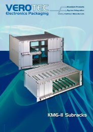
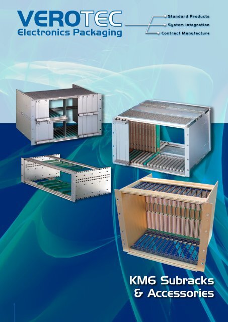
KM6 Subracks<br />
& Accessories
KM6 Subrack - Index<br />
1 KM6 Subracks<br />
K M 6 S U B R A C K S<br />
OVERVIEW 1-16<br />
An introduction to subrack systems 3<br />
Eurocard dimensional criteria for<br />
KM6 subrack systems 4<br />
IEC 60297-3 dimensional criteria 5-6<br />
IEEE 1101.10/11 dimensional criteria 7-11<br />
A guide to EMC screening subracks 12<br />
Shock and vibration 13<br />
Subrack materials and finishes 14<br />
Customising options 15<br />
A guide to KM6 subrack systems 16<br />
KM6-II SUBRACK SYSTEM 17-48<br />
Introduction to KM6-II 17<br />
KM6-II Dimensional criteria 18<br />
KM6-II Standard subracks 19-20<br />
KM6-II Universal subracks 21-22<br />
KM6-II EMC conversion 23-27<br />
KM6-II Subrack piece parts 28-32<br />
KM6-II Accessories 33-48<br />
KM6-RF SUBRACK SYSTEM 49-77<br />
Introduction to KM6-RF 49-52<br />
KM6-RF: 3U, Style A subracks 53-54<br />
KM6-RF: 3U, Style B subracks 55-56<br />
KM6-RF: 6U, Style A subracks 57-58<br />
KM6-RF: 6U, Style B subracks 59-60<br />
KM6-RF: 3U, 6U & 9U, Style C subracks 61-62<br />
KM6-RF Subrack piece parts 63-73<br />
KM6-RF Accessories 74-77<br />
KM6-II subrack system<br />
KM6-RF subrack system<br />
KM6-EC SUBRACK SYSTEM 79-82<br />
Introduction to KM6-EC 80<br />
KM6-EC Subracks 80<br />
KM6-EC Accessories 81-82<br />
KM6-HD SUBRACK SYSTEM 83-87<br />
Introduction to KM6-HD 83-84<br />
KM6-HD Subracks 84<br />
KM6-HD Subrack piece parts and accessories 85-87<br />
KM6-EC subrack system<br />
KM6-HD subrack system<br />
1.02 UK Tel: +44 (0)2380-246900 sales@verotec.co.uk<br />
USA Tel: 603.821.9921 sales@verotec.us
An introduction to subrack systems<br />
Our manufacturing facilities have long been at the forefront of technological<br />
development, and their commitment to the providing of the most fit-for-purpose<br />
products is demonstrated by the fact that we currently manufacture some of the<br />
most advanced packaging systems and enclosures available. <strong>Verotec</strong>’s facilities<br />
are fully equipped with the latest electronic design and manufacturing systems,<br />
enabling customers to access a “virtual” factory for the procurement of product.<br />
We have long experience in the design, manufacture and supply of subracks<br />
and enclosures in both standard and custom forms and, as a result, we have<br />
expertise in solving a wide range of problems encountered by the electronics<br />
industry when housing or ‘packaging’ components and systems. This<br />
publication reflects both that experience and expertise.<br />
<strong>Verotec</strong>s is dedicated to being a world-class provider of a comprehensive<br />
range of standard and custom product, borne from the integrated design,<br />
manufacturing and service capabilities, enabling it to provide OEMs with rapid<br />
deliveries at competitive prices. We believe that every customer is a priority,<br />
and contact is maintained by means of our own dedicated sales forces and via<br />
our technical sales and marketing specialists, who are able to draw upon global<br />
resource.<br />
Subracks<br />
The KM6 subrack range; KM6-II, KM6-RF, KM6-EC and KM6-HD, is recognised<br />
worldwide as one of the leading products in its field having evolved around<br />
a number of international standards and in response to a number of trends.<br />
Principal among these trends are increased component densities, higher speed<br />
bus systems, greater connector contact counts, a greater range of operating<br />
environments, EMC and electrical safety regulations and, of course, economic<br />
pressures.<br />
The Subrack principle<br />
Why would you choose to use an extrusion based subrack ?<br />
In a word, accuracy. The need to provide a precise framework in which PCBs<br />
are supported and guided into connector positions is most efficiently achieved<br />
using accurate extrusion technology and hard-tooled end plate design. The<br />
subrack function now extends far beyond the pure support role and covers such<br />
areas as RFI protection, Shock and vibration protection, ESD protection and Fire<br />
enclosure safety to name but a few. Let’s examine a number of the functional<br />
aspects of the subrack and look at the alternative solutions available<br />
RFI protection<br />
This is achieved by the use of covers, EMC contact fingers and conductively<br />
finished mating parts. The Faraday cage achieved with subracks can give very<br />
high levels of signal attenuation across a wide band of frequencies. The nature<br />
of the construction also allows the user to define a balance between EMC and<br />
ventilation. Selective RFI protection is another option, with the use of plug in<br />
screened modules.<br />
There are a couple of alternatives, either the problem can be designed out at<br />
board level ( there is some doubt, however, that susceptibility problems can be<br />
designed out through tracking and layout changes), or the problem areas can<br />
be ‘canned’, but again there are some doubts regarding susceptibility.<br />
Shock and vibration<br />
This is achieved with the use of secure card guides (screwed in), two point<br />
extrusion to endplate fixing and additional mounting at the rear of the frame. It<br />
should be remembered that the effectiveness of the mounting is only as good<br />
as the rack/system into which the frame is mounted.<br />
There are only custom solutions for securely mounting PCBs without using a<br />
subrack and these are normally loosely based around the subrack principle.<br />
1 KM6 Subracks<br />
ESD protection<br />
This is achieved using grounding clips in the card guide system to discharge<br />
Electrostatic build up from the PCB either during insertion or during the course<br />
of normal operation in situ. Additional grounding at the front panel is now seen<br />
as good ESD practise and this is achieved either with the use of metal inserts or<br />
through the grounding pin in IEEE1101.10 Injector/Ejector mechanisms.<br />
Alternative methods of ESD are hard to define. Some claim that good<br />
production methods ie .operators fitted with discharge clips and product<br />
storage in anti-static packaging are helpful. Others claim sufficient discharge<br />
through an allocated pin(s) in the connector.<br />
Extrusion based subrack<br />
RFI protected subrack<br />
Versatility<br />
The Subrack concept allows the user to configure the usable space to suit<br />
the application, thus removing the necessity to ‘tool’ each configuration as a<br />
custom solution.<br />
Divider kits for the front and rear allow a variety of heights, widths and depths<br />
within a single envelope size. Even the orientation of the PCBs can be readily<br />
changed from vertical to horizontal, or indeed a combination of the two within<br />
the same frame.<br />
The alternative to this is to produce a custom based solution, which may<br />
well produce a high tooling investment requirement. <strong>Verotec</strong> have made a<br />
significant investment in tooling to produce good quality, versatile subrack<br />
products.<br />
UK Tel: +44 (0)2380-246900 sales@verotec.co.uk<br />
USA Tel: 603.821.9921 sales@verotec.us<br />
1.03
Eurocard dimensional criteria for KM6 subrack systems<br />
1 KM6 Subracks<br />
Introduction<br />
KM6 Subracks are designed around a number of dimensional standards that<br />
aim to provide a basic level of interchangeability between different versions<br />
and between manufacturers of similar systems.<br />
The basis is the DIN41494 Eurocard standard. The dimensions for the housing<br />
of Eurocards are described in IEC60297 section 3 SC48D. Plug-in units are<br />
modular in concept and are based on the first card position being 3,27mm<br />
from the left hand datum line of the working aperture; subsequent card<br />
positions are on multiples of 5,08mm (1HP) from this first card position.<br />
To allow for a uniform working clearance between front panels, when used,<br />
the overall width of a front panel is 0,4mm less than the nominal HP x 5,08<br />
dimensions generally quoted.<br />
Heights are nominally quoted in U’s (multiples of 44,45mm) but it should<br />
be borne in mind that a device quoted as nU high will not be n x 44,45mm in<br />
overall height.<br />
Guide clearance<br />
KM6- subracks can accommodate connectors to IEC130-4, DIN41612 and<br />
VG95324 specifications or motherboards to the IEC60297-3 specification<br />
In addition, reference will be found to the IEEE1101.1, .10 and .11 which<br />
expand on the above specifications and for which KM6-RF provides suitable<br />
product. These describe a number of features particularly relevant to<br />
VME64x, CompactPCI® and PXI bus structures.<br />
SINGLE EUROCARD<br />
front panel/mounting holes<br />
card ejector<br />
connector mounting holes<br />
Eurocards - Critical Dimensions<br />
As with the rest of the system the printed circuit board sizes are<br />
standardised. All PCBs should be of the Eurocard size and conform to the<br />
layout shown.<br />
A 2,50mm wide border is necessary at the top and bottom of printed circuit<br />
boards to allow clearance for fitting into card guides and for mounting into<br />
plug-in unit guide rails.<br />
Guide clearance<br />
connector mounting holes<br />
front panel/card<br />
ejector mounting holes<br />
On the double height Eurocard, owing to the overall size and position of the<br />
connectors, it is recommended that when fitting components to the front<br />
panels the grid as laid out here is adopted. This will allow consistency<br />
between 3U and 6U height front panels if mixed configurations are utilised.<br />
Useful Front Panel and Circuit Board Dimensions<br />
These dimensions are useful when a Eurocard is to be attached to a KM6<br />
front panel using card mounting brackets.<br />
DOUBLE EUROCARD<br />
Connector type (DIN 41612) B C D E F G H<br />
DIM X 7,6 9,4 9,4 14,4 11,3 16,3 11,3<br />
Subrack front section features<br />
Adjacent front<br />
panel positions<br />
Card depth + 9,93 (con types B,C,D)<br />
+ 11,93 (con types F,G,H)<br />
Normal<br />
position<br />
Please note: Certain plastics can be adversely affected by organic solvents. Care<br />
should be taken to avoid contamination by some cleaning agents, for instance.<br />
With modified PPO's and PPE's such as Luranyl we recommend that when using<br />
thread locking compounds they should be cyanoacrylate based, not anaerobic.<br />
1.04<br />
UK Tel: +44 (0)2380-246900 sales@verotec.co.uk<br />
USA Tel: 603.821.9921 sales@verotec.us
IEC 60297-3 dimensional criteria<br />
These illustrations show dimensions extracted from IEC 60297-3.<br />
They are not comprehensive, but should prove generally informative<br />
2,54<br />
First<br />
fastening<br />
location<br />
5,08 Typ<br />
A<br />
1 KM6 Subracks<br />
3U = 133,35 Nominal<br />
PCB Positions incrementally<br />
by 5,08 multiples<br />
Eurocard<br />
Compatible<br />
100 +0/ -0,30<br />
Aperture 112<br />
3,27<br />
Aperture > 84 x 5,08<br />
A<br />
'X'<br />
482,6 Nominal<br />
Centre line first<br />
PCB<br />
To accommodate PCB 1,6mm±0,2<br />
3<br />
2<br />
11,75<br />
Pitch line<br />
10,16<br />
6<br />
Detail 'X'<br />
< 449<br />
> 22<br />
Rear attachment plane<br />
Scrap view of 6U showing<br />
dimensions available for<br />
centre rear extrusion with<br />
6U plug-in units<br />
'Y'<br />
Subrack dimensions shown are for 3U x 84HP and single Eurocards<br />
Heights increment by 44,45mm (1U)<br />
Widths increment by 5,08mm (1HP)<br />
Pitch line<br />
2,54<br />
Detail 'Y'<br />
UK Tel: +44 (0)2380-246900 sales@verotec.co.uk<br />
USA Tel: 603.821.9921 sales@verotec.us<br />
1.05
IEC 60297-3 dimensional criteria<br />
1 KM6 Subracks<br />
'W'<br />
'Z'<br />
1,5<br />
Motherboard<br />
fixing centres<br />
122,5<br />
6<br />
Front panel fixing<br />
centres 122,5<br />
Detail 'Z'<br />
Guide<br />
*Rear attachment plane<br />
(i.e. Connector Mounting Face)<br />
For DIN 41612 types BCDMQRS<br />
For types FGUV add 10mm<br />
175,24 *<br />
Section 'A-A'<br />
Front attachment plane<br />
Detail 'W'<br />
Optional<br />
spacer m 3<br />
Alternative detail 'W'<br />
175,24*<br />
175,24*<br />
90<br />
DIN 41612<br />
connector mounted<br />
on motherboard<br />
Alternative for direct<br />
mounting of DIN 41612<br />
connectors<br />
'V'<br />
Fixing holes incrementing on<br />
multiples of 5,08 as required<br />
Fixing holes on multiples of 5,08<br />
2,5<br />
'U'<br />
7,62<br />
128,7<br />
122,5<br />
90<br />
Type ‘B’<br />
Type ‘C’<br />
2,5<br />
Limit of component<br />
mounting area<br />
Front attachment<br />
plane<br />
2,54<br />
Pitch line<br />
n x 5,08<br />
n x 5,08<br />
122,5±0,2<br />
128,7 +0/ -0,3<br />
Pitch line<br />
2,54<br />
7,62<br />
a b<br />
0,3<br />
a b c<br />
84 x 5,08<br />
Motherboard dimensions<br />
showing Type 'B' & 'C' DIN 41612<br />
connector positions Front view<br />
0,3<br />
4,07<br />
Pitch line<br />
2,7<br />
Detail 'U'<br />
8,8<br />
7,5<br />
3,6<br />
Pitch line<br />
2,54<br />
PCB<br />
5,63<br />
5,63<br />
3,55<br />
Detail 'V'<br />
M2,5<br />
1.06<br />
UK Tel: +44 (0)2380-246900 sales@verotec.co.uk<br />
USA Tel: 603.821.9921 sales@verotec.us
IEEE 1101.10/11 dimensional criteria<br />
Introduction<br />
IEEE1101.1 is largely a reiteration of the basic IEC60297-3 standard, with some<br />
changes to reflect .10 and .11<br />
IEEE110.10 was driven by a number of requirements:<br />
The standardisation of EMC front panel geometry to ensure compatibility<br />
between various manufacturers’ products.<br />
The introduction of the five-row DIN41612 connector into VME and the<br />
incorporation of Metric standard connectors. Both have very high pin counts<br />
and resultant high insertion / withdrawal forces that require a standard injector/<br />
extractor handle geometry.<br />
Injector / Extractor operating<br />
feature<br />
EMC seals<br />
Infill (blank) panel<br />
Box type plug in unit<br />
1 KM6 Subracks<br />
The standard also addresses the problems of electrostatic protection and a need<br />
to code plug-in units to prevent incorrect plug-up, where such actions could<br />
have catastrophic results (in particular in live insertion situations).<br />
IEEE1101.11 standardises the geometry of rear plug-up (transition) modules<br />
where no previous standard existed.<br />
Rear plug-up - or transition - is used and required within the core specifications<br />
of major open-architecture bus structures where a midplane is used to provide a<br />
rear I/O interface.<br />
Coding / ESD feature<br />
Injector / Extractor<br />
Typical arrangement of 1101.10 subrack<br />
Conductive surfaces or EMC gasket<br />
2,0 max<br />
2,5 min<br />
0,5 min<br />
1,0 max<br />
Subrack conductive areas<br />
5,08<br />
10<br />
5,5<br />
2,54<br />
2,54<br />
2,5<br />
3,5<br />
5,08<br />
Subrack Injector / extractor operating feature<br />
4 x 5,08<br />
3 x 5,08 5,08<br />
15,24<br />
10,16<br />
2,54<br />
5,08<br />
2,5<br />
3,4Ø(dia)<br />
2,54 2,54 2,54<br />
Subrack mounted coding / ESD feature<br />
UK Tel: +44 (0)2380-246900 sales@verotec.co.uk<br />
USA Tel: 603.821.9921 sales@verotec.us<br />
<strong>1.07</strong>
IEEE 1101.10/11 dimensional criteria<br />
1 KM6 Subracks<br />
Typical plug-in unit showing injector /<br />
extractor coding, ESD and front panel<br />
geometry<br />
4,9<br />
3,1<br />
3,1<br />
4,75<br />
13,0<br />
Interaction of coding key<br />
4 max<br />
(1,6)<br />
2,4<br />
4,6<br />
7,6<br />
Protective cover (optional)<br />
(1,5)<br />
(1,32)<br />
(13,71)<br />
(max component<br />
height)<br />
(2,54)<br />
14,1<br />
3,8 max<br />
2,5<br />
2,0 max<br />
2,4<br />
1,0<br />
4,4<br />
Coding key<br />
2,1<br />
23 max<br />
3,8 max<br />
2,5 min<br />
1,26<br />
1,15 max<br />
4HP (4 x 5,08)<br />
Typical<br />
0,5 min<br />
1,0 max<br />
Plug-in unit detail<br />
1,5<br />
14,5<br />
10<br />
2,5<br />
Usable component space<br />
106 (3U)<br />
239.35 (6U)<br />
372.7 (9U)<br />
Test dimension (N x U) - 4,35 + 0,55<br />
- 0,0<br />
38<br />
3,8<br />
Location ESD detail<br />
Detail for extractor<br />
1.08<br />
UK Tel: +44 (0)2380-246900 sales@verotec.co.uk<br />
USA Tel: 603.821.9921 sales@verotec.us
IEEE 1101.10/11 dimensional criteria<br />
Subrack front view<br />
Alignment / ESD feature<br />
A B C Alignment / ESD pin C B A<br />
Board type Plug-in unit<br />
Rear View<br />
1 KM6 Subracks<br />
1 2 3 4 Empty<br />
1 2 3 4 Empty<br />
Keying Options<br />
Printed Board<br />
1 2 3 4 Empty<br />
1 2 3 4 Empty<br />
D E F<br />
F E D<br />
Keying chamber<br />
(subrack mounted)<br />
Front Extrusion<br />
Keying chamber<br />
front panel<br />
Front attachment plane<br />
Guide rail<br />
10<br />
60<br />
Guide rail ESD contact area<br />
0,5<br />
1,5<br />
2,5<br />
2,76<br />
0,5<br />
(160) (160)<br />
153,67<br />
2,76<br />
(153.67)<br />
70<br />
0,5 5<br />
Component side<br />
Component side<br />
Rear<br />
Rear<br />
ESD contact breaks before connector engagement<br />
ESD contact maintained during connector engagement<br />
PCB ESD Contact strips top / bottom<br />
UK Tel: +44 (0)2380-246900 sales@verotec.co.uk<br />
USA Tel: 603.821.9921 sales@verotec.us<br />
1.09
IEEE 1101.10/11 dimensional criteria<br />
1 KM6 Subracks<br />
Injector / extractor operating<br />
feature<br />
EMC seals<br />
Typical arrangement of 1101.11 subrack<br />
with rear plug-up<br />
Rear (transition) plug-up unit<br />
Midplane<br />
Infill (blank)<br />
panel<br />
Coding ESD<br />
feature<br />
Injector / extractor<br />
Rear (transition) plug-up unit/front panel<br />
Mid plane<br />
EMC seals<br />
Front (transition) plug-up unit/front panel<br />
In line configuration for rear (transition)<br />
plug-up EMC panels.<br />
Midplane<br />
Db<br />
Da<br />
160<br />
153,67<br />
Dimensions refer to<br />
160 unit<br />
Front<br />
100 3U<br />
233,35 6U<br />
366,7 9U<br />
Rear<br />
400 340 280 220 160 100 60 80 100 120 140 160<br />
Front rear plug-up options<br />
1.010 1.10<br />
UK Tel: +44 (0)2380-246900 sales@verotec.co.uk<br />
USA Tel: 603.821.9921 sales@verotec.us
IEEE 1101.10/11 dimensional criteria<br />
6<br />
Midplane<br />
Rear plug-up<br />
dimensions<br />
(160 shown)<br />
1 KM6 Subracks<br />
max 6<br />
170.3 (IEC 603-2)<br />
172.8 (1076.4.x)<br />
Spacer (user<br />
defined)<br />
See IEEE 1101.1<br />
Locking interface<br />
See IEC603-21<br />
1076-4-x<br />
182.48<br />
Attachment plane<br />
Rear free<br />
connector<br />
Front fixed<br />
connector<br />
Rear fixed<br />
connector<br />
Inspection Dimension<br />
169.88 (IEC 603-2)<br />
172.38 (IEC 1076-4-x)<br />
(160 shown)<br />
Rear (transition) plug up<br />
detail 3U shown<br />
160<br />
ESD / Electrical safety ground<br />
Frame mounted coding / ESD / location / electrical<br />
safety ground feature<br />
UK Tel: +44 (0)2380-246900 sales@verotec.co.uk<br />
USA Tel: 603.821.9921 sales@verotec.us<br />
1.011 1.11
A guide to EMC screening subracks<br />
1 KM6 Subracks<br />
A Guide to the EMC screening subracks<br />
Please note that any reference in this section to attenuation figures is theoretical,<br />
and examples have been obtained under laboratory conditions only.<br />
By its nature, an empty enclosure does not fall within the scope of any EMC<br />
performance regulation, since all the existing standards are applicable solely<br />
to electrical/electronic equipment; any modification to either the enclosure<br />
or its contents will have an effect upon its EMC performance.<br />
While KM6-RF is supplied with full line capability as standard, some sizes<br />
of KM6-II, KM6-EC and KM6-HD can be retrospectively screened by the<br />
addition of covers, front panels and associated components. These can be<br />
found by reference to the various details in this catalogue.<br />
Continuous<br />
Effect of Be Cu Spacing on single front and rear panels solid top and bottom covers with<br />
dimples at 20mm spacing Be Cu IN 4-finger blocks<br />
The key to good screening performance in the E (electrical) field is to limit<br />
the size of any holes and the real-estate between them, and to reduce<br />
the length of slots, on the basis that the shorter the slot, the better the<br />
performance at higher frequencies. The H (magnetic) field performance is<br />
more a function of material and thickness - hence a steel cover would offer<br />
some improvement in this area.<br />
The cover kits are available in ventilated and unventilated form and their<br />
typical performance can be fairly accurately forecast, assuming that they<br />
are fitted in the recommended way. The obvious difference is that the<br />
unventilated version offers a higher level of attenuation. Despite the fact<br />
that aluminium has good thermal properties, however, it must be accepted<br />
that you may have heat dissipation problems. The choice of ventilation holes<br />
is necessarily a compromise between EMC, thermal and manufacturing<br />
considerations. We have chosen with these in mind. Apart from this,<br />
the only means that can easily be used to further enhance the standard<br />
screening performance in this area is to apply an appropriate EMC gasket<br />
around all edges, thus reducing slots to the minimum; under laboratory<br />
conditions we achieved an improvement of approximately 15dB using seals<br />
in this manner. For this sort of application there are self-adhesive stainless<br />
steel or copper alloy gasket strips readily available from EMC seal suppliers.<br />
Attenuation (dB)<br />
Frequency - MHz<br />
Continuous 11mm Spacing 27mm Spacing 44mm Spacing<br />
RFI fingers fitted on front and/or rear extrusions when using<br />
overall closing panels.<br />
Published Data<br />
The area of EMC shielding which is most open to variables is in the sealing of<br />
the front and rear panels. Here, adjusting the spacing of the RFI fingers can<br />
produce significantly different performances and whilst this guide is not all<br />
encompassing in this matter, it will assist you. Hence, all other factors being<br />
equal, maximum performance can be achieved by using full width front<br />
panels, thus reducing the number of potential leakage points.<br />
RFI fingers<br />
fitted at all<br />
vertical corners<br />
Shown here is a set of typical plots obtained under test conditions using<br />
various finger configurations, from small groups at varying intervals up to a<br />
full strip of fingers. The subrack was fitted with unventilated top and bottom<br />
covers throughout the test. The 11mm curve is anomalous at 300MHz<br />
which is due to a function of the geometry of the particular enclosure under<br />
test. Figures are averaged from front and rear. Ventilated covers reduce<br />
the attenuation by an average of 15% under test conditions. The lower<br />
attenuations at 100 MHz are a result of the measurement method, and do<br />
not reflect an inferior level of shielding. The effect of slot length is clearly<br />
shown at increasing frequencies. EMC fingers can add significant cost to<br />
the screening of a system and for this reason, we do not include fingers in<br />
some instances; instead, you should select the configuration most suitable<br />
for your particular application, after consideration of the variables detailed in<br />
this section. The EMC finger strips can be easily cut to length with a pair of<br />
sharp scissors, taking care to avoid crushing the raised fingers.<br />
Spacing of fingers should be consistent throughout. They should be placed<br />
to coincide with those on the front and rear panels.<br />
End plate angles omitted for clarity<br />
1.12<br />
UK Tel: +44 (0)2380-246900 sales@verotec.co.uk<br />
USA Tel: 603.821.9921 sales@verotec.us
Shock and vibration<br />
The increasing use of electronics in such applications as mobile, roadside, factory<br />
and earthquake environments has led to an increased awareness of the effects of<br />
shock and vibration on full systems.<br />
The use of subracks in these conditions is generally limited by a number of factors.<br />
1) The loading - both total weight and its distribution; increased height to<br />
some extent improves the vertical stability; increasing width adversely<br />
affects its resistance to vibration in the vertical axis and the deflection of<br />
horizontal components; increasing depth encourages ‘parallelogramming’<br />
in sideways shock and vibration. Placing heavier components as close as<br />
possible to the major fixing points will also help in all axes.<br />
1 KM6 Subracks<br />
2) The overall construction - a box structure (ie one which has securely<br />
fitted top and bottom, front and rear covers) will be much more rigid than<br />
a simple framework. Here, backplanes, front and rear panels with multiple<br />
fixings, offer considerable benefit.<br />
3) Constraining the assembly at the rear, as well as the front, provides an<br />
extremely good return for the effort. Careful design here can prevent<br />
movement in sideways and vertical directions.<br />
4) Positive retention of guides adds to the capability of the assembly. It is<br />
recommended for particularly heavy plug-ins such as power supplies,<br />
especially in transit, where it may be subjected to vibration and shock on<br />
stiffly suspended trucks or during handling.<br />
Subrack shock and vibration<br />
5) The most difficult problem for the subrack manufacturer is to add<br />
as much material to extrusions whilst maintaining integrity with the<br />
dimensional standards such as IEEE1101.1, at as low a cost as possible<br />
and without restricting airflow too much.<br />
6) Large PCBs will react badly to sideways vibration and may require the<br />
incorporation of stiffening devices securely fixed at close intervals to<br />
prevent ‘snaking’ or ‘panting’, both of which put considerable stress on<br />
component connections.<br />
There are a large number of specifications and standards which can be invoked to<br />
express the testing requirements, some of which are very specific, some extremely<br />
widely drawn. Among the latter you may find military specifications which are<br />
intended to cover a wide range of environments from storage and transport,<br />
through ship-borne, to airborne and missile applications.<br />
It is important to note that whilst, <strong>Verotec</strong> can meet most requirements, over<br />
specifying test analysis will inevitably can lead to unnecessary cost penalties, with<br />
little overall again at the end of the process.<br />
In order to ensure that you select the right subrack, or request the correct test<br />
set before installing your systems, a discussion of your needs with one of our<br />
applications specialists may be beneficial.<br />
For further details please contact our Applications Support Team<br />
UK Tel: +44 (0)2380-246900 sales@verotec.co.uk<br />
USA Tel: 603.821.9921 sales@verotec.us<br />
1.13
Subrack materials and finishes<br />
1 KM6 Subracks<br />
Although aluminium can be seen as a more expensive material than, for<br />
instance, steel, it offers several benefits in the design and construction of<br />
subracks which makes it highly suitable. The reduction in weight which it<br />
offers is particularly useful for ‘one-man’ handling in restricted space and<br />
less than ideal heights.<br />
Additionally, it has excellent heat conduction properties.<br />
In extruded form, it is possible to design-in a wide variety of features which<br />
would be difficult and expensive to incorporate into formed and machined<br />
materials. It also permits easy changes of length.<br />
There are a number of ways of specifying the actual material - we use<br />
BS1474.6063 T6 extrusion.<br />
In sheet form, aluminium can offer good rigidity for its weight and is<br />
relatively easy to punch and half shear accurately, with minimum tool wear.<br />
Our aluminium sheet is BS EN485-2 5251 (H12-H26).<br />
Ideally, from the point of view of corrosion and scuff resistance and for a<br />
good decorative finish, anodising is excellent. Our in-house anodising is to<br />
our own specification and we are rightly proud of the excellent appearance<br />
it produces.<br />
A process known as ‘sub-surface printing’ is ideal where a permanent wear<br />
and chemical resistance are called for, consisting of identification printing<br />
before the application of the anodic film.<br />
Anodic film, which is electrolytically applied is an excellent insulator.<br />
It is therefore unsuitable in modern subrack systems which need to<br />
be electrically bonded due to problems from electrostatics; they also<br />
frequently have to be EMC screened by the application of covers and panels<br />
which must all be electrically continuous as far as possible.<br />
Subrack material and finishes<br />
( V0 is the highest level, V1 being generally as low as we would accept). It is<br />
important to note that the UL94 test has a number of gradations in thickness<br />
and test application.<br />
For that reason, most of <strong>Verotec</strong>’s subrack system components are now<br />
finished by means of a chromate conversion process (typical trade terms<br />
are Irridite, Alocrom, Alodine). This process ensures that the aluminium<br />
materials have a good degree of corrosion resistance, which in turn<br />
prevents ‘self anodising’ over time. Clear chromate has low surface<br />
resistivity (lower than the colour types) but because it is only a surface<br />
film can be affected by scuffing and finger-marking. For that reason, care<br />
should be taken during handling. However, it has a good appearance.<br />
From a production point of view, the use of steel in KM6-RF covers offers<br />
benefits in that it provides stiffness at lower thicknesses.<br />
We use mild steel sheet CR4 to BS EN10130<br />
One of the major problems associated with plastics is their susceptibility to<br />
attack by chemical solvents and we make frequent reference to this. This kind<br />
of damage frequently only shows when the material is under stress (when it is<br />
screwed down, for instance) and is commonly caused by threadlock compounds<br />
or cleaning solvents. Where breakages occur, a sample of the item concerned<br />
can usually establish the nature of the problem.<br />
It is important to note that most plastic components have fine ‘knit lines’ where<br />
the material flows join during the moulding process - they are not normally<br />
deleterious to performance although they are frequently mistaken for incipient<br />
cracks.<br />
In common with most steel components and fixings throughout the <strong>Verotec</strong><br />
subrack range, we use clear passivated zinc plating to provide corrosion<br />
resistance with an acceptable appearance - although the colour passivation<br />
used on tapped strips provides much greater protection against front panel<br />
fixing screws ‘freezing’ in prolonged use or harsh climatic environments.<br />
Moulded plastics are used where complex shaped components are used<br />
in large volumes. There is a huge range of basic materials available,<br />
but in general we are looking for a cost effective plastic that has good<br />
moulding properties, is mechanically and dimensionally stable over a<br />
fairly wide range of temperatures and humidities, and conforms to modern<br />
requirements in fire resistance. The latter is usually expressed as UL94- V*<br />
The addition of glass fibres adds to the strength of moulded components, and<br />
is typically used in applications like injector/ extractors. It is used judiciously<br />
because it tends to accelerate tool wear.<br />
Most of our moulded subrack components are produced in modified PPO<br />
(Polyphenylene Oxide) - typically under the trade names Luranyl or Noryl, or<br />
Polycarbonates - Makrolon for instance. The latter is also supplied in sheet form<br />
for transparent panels.<br />
In the area of EMC seals, there is a general trend to stainless steel, away from<br />
Beryllium Copper. The latter has excellent forming, spring, and conductive properties,<br />
but there is concern about its disposal at the end of equipment life cycles.<br />
1.14<br />
UK Tel: +44 (0)2380-246900 sales@verotec.co.uk<br />
USA Tel: 603.821.9921 sales@verotec.us
Customising options<br />
Customising Service<br />
<strong>Verotec</strong> has many years of experience in the design and production of<br />
customised subracks.<br />
Most of our standard subracks are easily modified in order to suit a wide range<br />
of applications.<br />
The list below gives the customising options available on each of our KM6<br />
systems. Also illustrated are examples of modified subracks which we currently<br />
produce for various customers.<br />
1 KM6 Subracks<br />
Please contact us for further advice and assistance.<br />
Customised KM6-II subrack<br />
Customising Options<br />
n<br />
n<br />
n<br />
n<br />
n<br />
n<br />
n<br />
n<br />
n<br />
n<br />
n<br />
n<br />
n<br />
n<br />
n<br />
n<br />
n<br />
n<br />
Height<br />
Width<br />
Depth<br />
Punching/Drilling<br />
Surface Printing<br />
Subsurface Printing<br />
Engraving<br />
Alocrom/Irridite<br />
Painting<br />
Plating<br />
Assembly<br />
Wiring<br />
Backplane Assembly<br />
Cooling<br />
Kitting<br />
Bulk Packing<br />
RFI Capability<br />
Anodising<br />
Special subrack<br />
Customised/printed front panels<br />
Customised KM6-subrack<br />
Customised side panel<br />
UK Tel: +44 (0)2380-246900 sales@verotec.co.uk<br />
USA Tel: 603.821.9921 sales@verotec.us<br />
1.15
A guide to KM6 subrack systems<br />
1 KM6 Subracks<br />
INTRODUCTION<br />
In order to meet the diverse mechanical, electrical and environmental<br />
requirements that today’s markets & applications demand, <strong>Verotec</strong> offer four<br />
distinct subrack ranges. All are designed around a number of dimensional<br />
standards that aim to provide a basic level of interchangeability between<br />
different versions and between manufactures of similar systems. The basis<br />
is the DIN 41494 Eurocard standard and the dimensions for the housing of<br />
Eurocards are described in IEC 60297-3, to which KM6-II is designed. KM6-RF<br />
too is designed around this specification but also meets the requirements of<br />
IEEE1101.10/11 which builds on IEC 60297-3 to offer additional functionality.<br />
For high volume and price sensitive applications such as infrastructure<br />
projects, the low cost KM6-EC is an ideal solution. <strong>Verotec</strong>’s answer to heavy<br />
duty applications is the KM6-HD subrack which is designed to meet MIL-<br />
STD-167 and therefore makes it suitable for applications where resistance to<br />
excess shock and vibration is required.<br />
KM6-II subrack system<br />
KM6-II SUBRACK SYSTEM<br />
Fully compatible with DIN 41494 part 5 and IEC 60297-3, KM6-II subracks<br />
are strong, versatile and easy to assemble. All tiebars have two screw fixing<br />
positions making the construction robust yet accurate and well suited to light<br />
and medium duty applications. The range is extensive, offering 3U, 4U, 6U<br />
and 9U heights in width of 24, 42, 60 & 84HP and depths of 160, 240, 300,<br />
360 & 420mm. KM6-II Subracks are supplied either in kit form or individual<br />
component parts and are complimented by a wide range of accessories,<br />
including EMC conversion kits, guides, front panels and plug-in modules.<br />
KM6-RF SUBRACK SYSTEM<br />
The KM6-RF subrack range meets the requirements of IEEE 1101.10 & 11,<br />
which expands on IEC60297 to add functionality required for modern industrial<br />
computing applications. This includes RFI shielding, a rear transition area, front<br />
panel ESD / coding and handles with an injector / extractor operating feature.<br />
KM6-RF is therefore well suited to VME64x, CompactPCI and PXI applications,<br />
serving typical markets such as Telecoms, Medical and Instrumentation.<br />
The range caters for various combinations of height, width and depth and is<br />
complimented by a wide range of accessories, including guides, front panels<br />
and plug-in modules. KM6-RF subracks are supplied in complete kits or in their<br />
component parts.<br />
KM6-RF subrack system<br />
KM6-EC SUBRACK SYSTEM<br />
KM6-EC subracks have been designed and are suitable for high volume, cost<br />
sensitive applications. Whilst they are still versatile and fully conform to the<br />
requirements of IEC60297, care has been taken to remove certain features<br />
found in the KM6-II range to reduce the manufacturing cost. These include<br />
lighter extrusion profiles, single-point tiebar fixings (rather than double) and<br />
Zintec side plates (rather than aluminium). They are backward compatible with<br />
many of the standard KM6-II accessories including card guides, front panels,<br />
plug-in modules and covers.<br />
KM6-HD SUBRACK SYSTEM<br />
KM6-EC subrack system<br />
The KM6-HD subrack system although primarily designed for military use,<br />
would suit any rugged application where a resistance to shock and vibration<br />
is required. Built to meet MIL-STD-167, its features include positive guide<br />
retention, heavy two screw fixing tiebars, 3mm thick side plates & rack angles<br />
and a conductive finish throughout. The KM6-HD subrack accepts standard<br />
Eurocards in 3U, 6U & 9U heights and depths of up to 400mm in both the<br />
IEC 297 and IEEE 1101.10 standards. They are supplied fully assembled and<br />
complimented by the standard range of KM6 accessories.<br />
KM6-HD subrack system<br />
1.16<br />
UK Tel: +44 (0)2380-246900 sales@verotec.co.uk<br />
USA Tel: 603.821.9921 sales@verotec.us