Download PDF (1.07 Mb) - Verotec
Download PDF (1.07 Mb) - Verotec
Download PDF (1.07 Mb) - Verotec

Create successful ePaper yourself
Turn your PDF publications into a flip-book with our unique Google optimized e-Paper software.
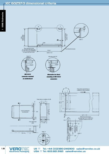
IEC 60297-3 dimensional criteria<br />
1 KM6 Subracks<br />
'W'<br />
'Z'<br />
1,5<br />
Motherboard<br />
fixing centres<br />
122,5<br />
6<br />
Front panel fixing<br />
centres 122,5<br />
Detail 'Z'<br />
Guide<br />
*Rear attachment plane<br />
(i.e. Connector Mounting Face)<br />
For DIN 41612 types BCDMQRS<br />
For types FGUV add 10mm<br />
175,24 *<br />
Section 'A-A'<br />
Front attachment plane<br />
Detail 'W'<br />
Optional<br />
spacer m 3<br />
Alternative detail 'W'<br />
175,24*<br />
175,24*<br />
90<br />
DIN 41612<br />
connector mounted<br />
on motherboard<br />
Alternative for direct<br />
mounting of DIN 41612<br />
connectors<br />
'V'<br />
Fixing holes incrementing on<br />
multiples of 5,08 as required<br />
Fixing holes on multiples of 5,08<br />
2,5<br />
'U'<br />
7,62<br />
128,7<br />
122,5<br />
90<br />
Type ‘B’<br />
Type ‘C’<br />
2,5<br />
Limit of component<br />
mounting area<br />
Front attachment<br />
plane<br />
2,54<br />
Pitch line<br />
n x 5,08<br />
n x 5,08<br />
122,5±0,2<br />
128,7 +0/ -0,3<br />
Pitch line<br />
2,54<br />
7,62<br />
a b<br />
0,3<br />
a b c<br />
84 x 5,08<br />
Motherboard dimensions<br />
showing Type 'B' & 'C' DIN 41612<br />
connector positions Front view<br />
0,3<br />
4,07<br />
Pitch line<br />
2,7<br />
Detail 'U'<br />
8,8<br />
7,5<br />
3,6<br />
Pitch line<br />
2,54<br />
PCB<br />
5,63<br />
5,63<br />
3,55<br />
Detail 'V'<br />
M2,5<br />
1.06<br />
UK Tel: +44 (0)2380-246900 sales@verotec.co.uk<br />
USA Tel: 603.821.9921 sales@verotec.us