Download PDF (1.07 Mb) - Verotec
Download PDF (1.07 Mb) - Verotec
Download PDF (1.07 Mb) - Verotec

You also want an ePaper? Increase the reach of your titles
YUMPU automatically turns print PDFs into web optimized ePapers that Google loves.
Eurocard dimensional criteria for KM6 subrack systems<br />
1 KM6 Subracks<br />
Introduction<br />
KM6 Subracks are designed around a number of dimensional standards that<br />
aim to provide a basic level of interchangeability between different versions<br />
and between manufacturers of similar systems.<br />
The basis is the DIN41494 Eurocard standard. The dimensions for the housing<br />
of Eurocards are described in IEC60297 section 3 SC48D. Plug-in units are<br />
modular in concept and are based on the first card position being 3,27mm<br />
from the left hand datum line of the working aperture; subsequent card<br />
positions are on multiples of 5,08mm (1HP) from this first card position.<br />
To allow for a uniform working clearance between front panels, when used,<br />
the overall width of a front panel is 0,4mm less than the nominal HP x 5,08<br />
dimensions generally quoted.<br />
Heights are nominally quoted in U’s (multiples of 44,45mm) but it should<br />
be borne in mind that a device quoted as nU high will not be n x 44,45mm in<br />
overall height.<br />
Guide clearance<br />
KM6- subracks can accommodate connectors to IEC130-4, DIN41612 and<br />
VG95324 specifications or motherboards to the IEC60297-3 specification<br />
In addition, reference will be found to the IEEE1101.1, .10 and .11 which<br />
expand on the above specifications and for which KM6-RF provides suitable<br />
product. These describe a number of features particularly relevant to<br />
VME64x, CompactPCI® and PXI bus structures.<br />
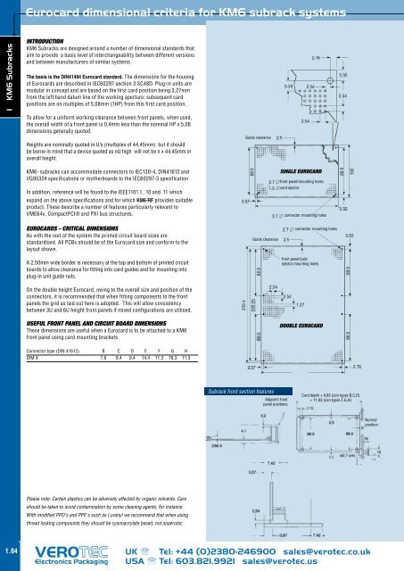
SINGLE EUROCARD<br />
front panel/mounting holes<br />
card ejector<br />
connector mounting holes<br />
Eurocards - Critical Dimensions<br />
As with the rest of the system the printed circuit board sizes are<br />
standardised. All PCBs should be of the Eurocard size and conform to the<br />
layout shown.<br />
A 2,50mm wide border is necessary at the top and bottom of printed circuit<br />
boards to allow clearance for fitting into card guides and for mounting into<br />
plug-in unit guide rails.<br />
Guide clearance<br />
connector mounting holes<br />
front panel/card<br />
ejector mounting holes<br />
On the double height Eurocard, owing to the overall size and position of the<br />
connectors, it is recommended that when fitting components to the front<br />
panels the grid as laid out here is adopted. This will allow consistency<br />
between 3U and 6U height front panels if mixed configurations are utilised.<br />
Useful Front Panel and Circuit Board Dimensions<br />
These dimensions are useful when a Eurocard is to be attached to a KM6<br />
front panel using card mounting brackets.<br />
DOUBLE EUROCARD<br />
Connector type (DIN 41612) B C D E F G H<br />
DIM X 7,6 9,4 9,4 14,4 11,3 16,3 11,3<br />
Subrack front section features<br />
Adjacent front<br />
panel positions<br />
Card depth + 9,93 (con types B,C,D)<br />
+ 11,93 (con types F,G,H)<br />
Normal<br />
position<br />
Please note: Certain plastics can be adversely affected by organic solvents. Care<br />
should be taken to avoid contamination by some cleaning agents, for instance.<br />
With modified PPO's and PPE's such as Luranyl we recommend that when using<br />
thread locking compounds they should be cyanoacrylate based, not anaerobic.<br />
1.04<br />
UK Tel: +44 (0)2380-246900 sales@verotec.co.uk<br />
USA Tel: 603.821.9921 sales@verotec.us